
High-speed dry gear hobbing is recognized as an efficient and environmentally friendly gear manufacturing process, widely applied in automotive transmission systems. This method eliminates the need for cutting fluids, reducing environmental impact and operational costs. However, the process involves high-frequency alternating cutting forces, leading to significant vibrations that adversely affect machining stability, tool life, and gear quality. In this study, we analyze the vibration characteristics of high-speed dry gear hobbing and develop a multi-objective optimization model to enhance process performance. The primary goals are to minimize vibration levels and reduce cutting time, thereby improving overall efficiency and product quality.
The gear hobbing process utilizes a hob with multiple cutting edges to generate gear teeth through a continuous rolling motion. The interaction between the hob and workpiece involves complex dynamics, where intermittent cutting actions induce periodic forces. These forces excite the structural modes of the gear hobbing machine, resulting in vibrations that can compromise machining accuracy. To address this, we begin by examining the fundamental principles of gear hobbing and the associated vibration mechanisms. A critical aspect is the identification of the dominant vibration frequencies, which are influenced by the hob geometry and cutting parameters. The tooth passing frequency, a key parameter, is calculated as:
$$f_n = \frac{n_h Z_k}{60}$$
where \( f_n \) is the tooth passing frequency in Hz, \( n_h \) is the spindle speed in rpm, and \( Z_k \) is the number of hob grooves. This frequency often aligns with the natural frequencies of the machine structure, potentially leading to resonance if not properly controlled.
To model the dynamic behavior of the gear hobbing machine, we consider a two-degree-of-freedom system representing the hob spindle. The equations of motion in the radial (X_h) and axial (Z_h) directions are given by:
$$m_x \ddot{x}(t) + c_x \dot{x}(t) + k_x x(t) = F_x(t)$$
$$m_z \ddot{z}(t) + c_z \dot{z}(t) + k_z z(t) = F_z(t)$$
Here, \( m_x \) and \( m_z \) are the equivalent masses, \( c_x \) and \( c_z \) are the damping coefficients, \( k_x \) and \( k_z \) are the stiffness values, and \( F_x(t) \) and \( F_z(t) \) are the dynamic cutting forces in the respective directions. This model helps in understanding how process parameters affect vibration responses.
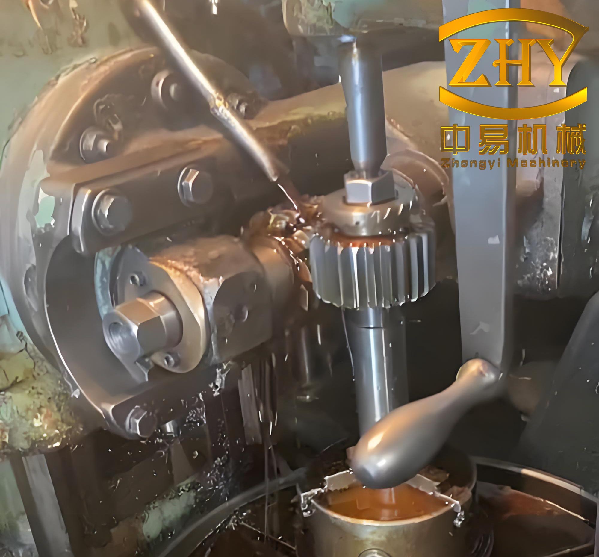
We conducted an orthogonal experiment to investigate the effects of spindle speed and axial feed rate on vibration characteristics. The gear hobbing machine used in this study was instrumented with accelerometers and current probes to capture vibration signals and motor currents during machining. The workpiece was a cylindrical gear with specific parameters, and the hob had defined geometry. The experimental factors and levels are summarized in Table 1.
| Parameter | Levels |
|---|---|
| Spindle Speed, \( n_h \) (rpm) | 550, 650, 750, 850, 950 |
| Axial Feed Rate, \( f_a \) (mm/r) | 0.5, 1.0, 1.5, 2.0, 2.5, 3.0 |
Vibration data were collected during the full-cutting phase of gear hobbing, where the hob engages the workpiece completely. Signals were processed using time-synchronous averaging (TSA) to eliminate noise and highlight periodic components related to the cutting process. The TSA method is expressed as:
$$m(t) = \frac{1}{N} \sum_{l=0}^{N-1} x(t + lP)$$
where \( m(t) \) is the averaged signal, \( N \) is the number of cycles, and \( P \) is the period of one hob revolution. This approach reduces random variations and enhances the reliability of vibration analysis.
The vibration characteristics were evaluated using several time-domain indicators, including maximum amplitude, variance, standard deviation, and root mean square (RMS). However, to comprehensively assess the vibration behavior, we introduced a composite indicator \( I_C \) that integrates multiple features. This indicator is defined as:
$$I_C = \frac{1}{n} \sqrt{\frac{1}{n} \sum_{i=1}^{n} (|Y_i – \bar{Y}|)^4}$$
where \( n \) is the number of data points, \( Y_i \) are the TSA-processed vibration values, and \( \bar{Y} \) is their mean. The composite indicator \( I_C \) provides a sensitive measure of vibration intensity, capturing changes under different process conditions.
Our analysis revealed that the axial feed rate has a more pronounced effect on vibration than spindle speed. Specifically, increasing the feed rate leads to a monotonic rise in vibration amplitudes, whereas spindle speed exhibits a non-monotonic influence. At lower feed rates, variations in spindle speed cause minimal changes in vibration, but at higher feed rates, the effect becomes significant. For instance, when the feed rate is 3.0 mm/r, increasing spindle speed from 550 rpm to 750 rpm amplifies vibrations, but further increases to 950 rpm reduce them. This behavior is attributed to the dynamic response of the gear hobbing machine structure and the cutting force characteristics.
To quantify the relationship between process parameters and vibration, we developed empirical models for the composite indicator \( I_C \). Two fitting approaches were employed: a third-order polynomial and an exponential function. The polynomial model is given by:
$$I_{C3} = 8.59 \times 10^{-11} n_h^3 – 1.87 \times 10^{-7} n_h^2 + 1.34 \times 10^{-4} n_h – 2.59 \times 10^{-8} n_h^2 f_a + 1.19 \times 10^{-6} n_h f_a^2 + 3.68 \times 10^{-5} n_h f_a + 8.91 \times 10^{-5} f_a^3 – 9.75 \times 10^{-4} f_a^2 – 1.19 \times 10^{-2} f_a – 0.0315$$
The exponential model is:
$$I_{Ce} = (-2.90 \times 10^{-8} n_h^2 + 5.00 \times 10^{-5} n_h – 0.02) e^{0.42 f_a} + 1.42 \times 10^{-2} – 4.26 \times 10^{-5} n_h + 1.71 \times 10^{-3} f_a + 2.49 \times 10^{-8} n_h^2 – 3.63 \times 10^{-6} n_h f_a – 2.89 \times 10^{-4} f_a^2$$
Both models showed high accuracy, with the polynomial fit achieving 95.7% precision. Therefore, we selected the polynomial model for optimization purposes.
In addition to vibration, machining efficiency is a critical consideration. The total cutting time for gear hobbing includes the time for the hob to traverse the gear width, along with approach and overtravel distances. The cutting time \( t_{cut} \) is calculated as:
$$t_{cut} = \frac{L_{ct} + L_{ot} + b_w + 4}{n_h f_a N_h / z_g}$$
where \( L_{ct} \) is the approach distance, \( L_{ot} \) is the overtravel distance, \( b_w \) is the gear width, \( N_h \) is the number of hob starts, and \( z_g \) is the number of gear teeth. The approach and overtravel distances depend on the hob and workpiece geometry, as well as the cutting depth. For our setup, these values were derived based on standard gear hobbing practices.
We formulated a multi-objective optimization problem to minimize both the vibration composite indicator \( I_C \) and the cutting time \( t_{cut} \). The decision variables are the spindle speed \( n_h \) and axial feed rate \( f_a \), constrained within the ranges used in the experiment. The optimization model is stated as:
$$\min f(n_h, f_a) = (\min I_{C3}, \min t_{cut})$$
$$\text{subject to: } n_{h,\min} \leq n_h \leq n_{h,\max}$$
$$f_{a,\min} \leq f_a \leq f_{a,\max}$$
To solve this multi-objective problem, we employed the Pareto Dominance-Based Multi-objective Simulated Annealing (PDMOSA) algorithm, which efficiently explores the trade-off between conflicting objectives. The algorithm generates a set of Pareto-optimal solutions, representing the best compromises between vibration and cutting time. Subsequently, the Technique for Order Preference by Similarity to Ideal Solution (TOPSIS) method was applied to select the final optimal solution from the Pareto front. TOPSIS evaluates solutions based on their relative closeness to the ideal and anti-ideal points, ensuring a balanced decision.
The optimization results are presented in Table 2, which compares the single-objective optima and the selected compromise solution. The Pareto front illustrates the trade-off between vibration and cutting time, where improvements in one objective often come at the expense of the other.
| Solution Type | Spindle Speed (rpm) | Axial Feed Rate (mm/r) | Vibration Indicator \( I_C \) (m²/s⁴) | Cutting Time (min) |
|---|---|---|---|---|
| Min Vibration | 580 | 0.77 | 7.17 × 10⁻⁴ | 4.59 |
| Min Cutting Time | 880 | 2.93 | 4.49 × 10⁻³ | 0.80 |
| Optimal Compromise | 880 | 1.60 | 1.63 × 10⁻³ | 1.45 |
Validation experiments were conducted using the optimal parameters and compared with a baseline set commonly used in industry. The baseline parameters were a spindle speed of 700 rpm and an axial feed rate of 1.5 mm/r. Under the optimized conditions, the vibration composite indicator decreased by 23%, from \( 2.11 \times 10^{-3} \) to \( 1.63 \times 10^{-3} \) m²/s⁴, while the cutting time was reduced by 26%, from 1.96 min to 1.45 min. This demonstrates the effectiveness of the optimization approach in enhancing both stability and efficiency in gear hobbing.
Further analysis of the vibration signals confirmed that the optimized parameters result in lower amplitude oscillations, particularly in the axial direction of the hob spindle. Additionally, the geometric accuracy of the manufactured gears was assessed through measurements of the span over pins (M value). The results, shown in Table 3, indicate that gears produced with optimized parameters exhibit M values closer to the theoretical specification, with reduced dispersion. This improvement in dimensional accuracy underscores the role of vibration control in achieving high-quality gears.
| Parameter Set | Average M Value (mm) | Standard Deviation (mm) | Within Tolerance (%) |
|---|---|---|---|
| Baseline | 122.485 | 0.008 | 83.3 |
| Optimized | 122.492 | 0.005 | 100.0 |
The dynamics of the gear hobbing machine play a crucial role in determining the optimal process parameters. Modal analysis identified the natural frequencies of the hob spindle and workpiece spindle, which must be avoided to prevent resonance. For instance, the first natural frequency of the workpiece spindle in the radial direction is 322 Hz, which corresponds to a spindle speed of approximately 1200 rpm for a typical hob. By constraining the spindle speed below this threshold, we mitigate the risk of resonant vibrations.
In practice, the gear hobbing process involves multiple passes and complex tool-workpiece engagements. However, for simplicity, we focused on single-pass hobbing, which is common in high-speed applications. The cutting forces in gear hobbing are influenced by the chip formation process, which varies with the hob geometry and cutting conditions. The specific cutting force can be modeled as a function of the undeformed chip thickness, which in turn depends on the feed rate and spindle speed. Empirical force models often incorporate exponential relationships, such as:
$$F_c = K_c \cdot a_p \cdot f_a^m$$
where \( F_c \) is the cutting force, \( K_c \) is a material-dependent constant, \( a_p \) is the depth of cut, and \( m \) is an exponent typically between 0.7 and 0.9. This force model helps in predicting the dynamic loads that excite the machine structure.
The vibration signals collected during gear hobbing were analyzed in the frequency domain to identify dominant peaks corresponding to the tooth passing frequency and its harmonics. The frequency spectrum for a typical test condition is shown in Figure 1, where the fundamental frequency and its multiples are clearly visible. The amplitude of these peaks increases with higher feed rates, confirming the relationship between process parameters and vibration intensity.
To further enhance the optimization model, we considered the effects of tool wear and thermal loads, which are significant in high-speed dry gear hobbing. However, for this study, we assumed constant tool conditions to isolate the vibration effects. Future work could integrate these factors for a more comprehensive analysis.
The PDMOSA algorithm parameters were set as follows: initial temperature of 1000, cooling rate of 0.95, and 1000 iterations. These settings ensured a thorough exploration of the solution space. The TOPSIS method used equal weights for the two objectives, reflecting a balanced approach to optimization.
In conclusion, our study demonstrates that optimizing process parameters in high-speed dry gear hobbing can significantly reduce vibrations and cutting time. The composite vibration indicator \( I_C \) provides a robust measure for assessing process stability, and the multi-objective optimization framework enables the selection of parameters that balance efficiency and quality. The methods developed here can be applied to other gear hobbing machines and configurations, contributing to the advancement of sustainable manufacturing practices.
The gear hobbing machine’s structural integrity is paramount for achieving desired outcomes. Stiffness and damping properties of the spindle system directly influence vibration levels. By incorporating these properties into the dynamic model, we can predict vibration responses more accurately. Additionally, advanced signal processing techniques, such as wavelet analysis, could be used to detect transient vibration events during gear hobbing.
Overall, this research highlights the importance of vibration analysis in gear hobbing and provides a practical approach for process optimization. The integration of experimental data, empirical modeling, and multi-objective optimization offers a systematic method for improving the performance of high-speed dry gear hobbing processes. As industries strive for higher productivity and sustainability, such methodologies will become increasingly valuable.