
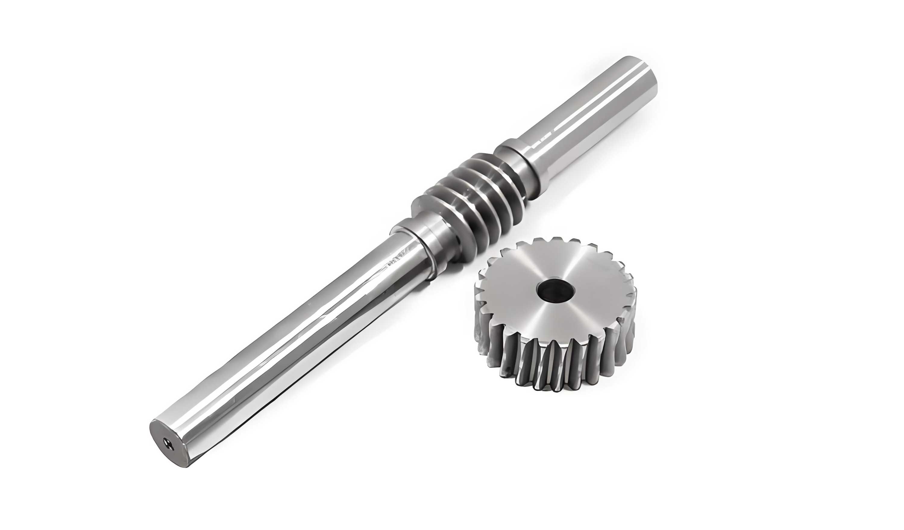
The enduring principle in worm gear design has traditionally favored a material combination of a hardened steel worm meshing with a softer gear, typically bronze or cast iron. This philosophy stems from the fundamental kinematics of the drive; for a single-start worm, the worm wheel tooth experiences significantly fewer load cycles compared to the rotating worm thread. This disparity logically suggests that the components should not share identical material specifications or target lifespans. While this conventional approach has proven functional, it inherently imposes limitations, particularly concerning wear resistance, overall longevity, and transmission efficiency.
My investigation challenges this established paradigm by proposing and validating a novel material configuration: a worm gear set where both the worm and the wheel are manufactured from hardened steel. This study presents a detailed comparative analysis between this new steel-on-steel pairing and a conventional steel-on-bronze pairing, focusing on performance under rigorous operational conditions.
Experimental Framework and Material Specifications
The core of this study was a meticulously designed comparative endurance test. Two geometrically identical worm gear reducers were constructed, differing only in the material of the worm wheel. The worm in both units was made from case-hardening steel 16MnCr55, heat-treated to a surface hardness of 58–62 HRC to ensure high wear resistance on the active thread flanks.
Table 1 details the precise geometrical parameters shared by both test units. These parameters define the fundamental kinematic and load-bearing characteristics of the worm gears.
| Parameter | Worm Wheel | Worm |
|---|---|---|
| Module (m) | 6 mm | 6 mm |
| Reference Diameter (d) | 156 mm | 44 mm |
| Number of Teeth / Starts (z) | 26 | 1 (implied) |
| Helix Angle / Lead Angle (γ) | — | 34° |
| Center Distance (a) | 100 mm | |
| Face Width (b) | 38 mm | — |
| Circumferential Pitch (p) | 18.84 mm | 18.84 mm |
Material Pairings:
- Test Unit A (Novel Configuration): Both worm and wheel manufactured from 16MnCr55 steel, with the wheel undergoing the same case-hardening treatment as the worm.
- Test Unit B (Conventional Configuration): Worm from 16MnCr55 steel; wheel from continuous cast tin bronze, grade CaSnN12 (analogous to ZQSn12-2).
The reducers were installed in a controlled test rig, each driven by a dedicated DC motor and instrumented with precision sensors to measure input/output speed, torque, temperature, and vibration. The operational regimen was designed to simulate demanding conditions: a continuous run for approximately 1,460 hours at a nominal input speed of 2,400 rpm, corresponding to a peripheral speed at the worm wheel relevant for many industrial applications.
Theoretical Basis for Efficiency Analysis
The efficiency of worm gears is primarily governed by sliding friction losses at the tooth interface. The theoretical efficiency (η) for a worm drive under load can be approximated by considering the lead angle (γ), the coefficient of friction (μ), and the pressure angle (α_n). A standard formula is:
$$
\eta = \frac{\tan \gamma}{\tan(\gamma + \rho’)}
$$
where ρ’ is the virtual friction angle, defined as \( \rho’ = \arctan(\mu / \cos \alpha_n) \). This clearly shows that for a given geometry, the coefficient of friction μ is the critical material-and-lubrication-dependent variable. Any reduction in μ directly increases efficiency. The comparative test essentially evaluates how the steel-on-steel material pairing, in conjunction with optimal lubrication, influences this effective friction coefficient compared to the traditional bronze pairing.
Comprehensive Results and Analysis
1. Transmission Efficiency: A Clear Superiority
The data on transmission efficiency revealed a consistent and significant advantage for the all-steel worm gears. Efficiency was monitored across a spectrum of input power levels, categorized into low-speed (200–600 rpm) and high-speed (1,400–2,400 rpm) operational bands to capture performance under different lubrication regimes (boundary vs. hydrodynamic).
The conventional bronze worm gear exhibited a stable but relatively low efficiency band, ranging between 85% and 88%, largely independent of the input power or speed within the tested range. This plateau is characteristic of such material pairs where the friction coefficient remains high.
In stark contrast, the efficiency of the steel-on-steel worm gear set demonstrated a positive correlation with input power. At low speeds and lower power, its efficiency started near the bronze pair’s level but increased steadily. At high operational speeds and powers, it achieved peak efficiencies approaching 95%. Figure 4 (conceptual data) illustrates this trend, showing the steel worm gear’s efficiency curve surpassing and diverging from the flat curve of the bronze gear, especially at higher energy throughputs exceeding 7,500 kWh. This substantial gain, often over 7 percentage points, translates directly into lower energy consumption and reduced thermal loading on the gearbox.
2. The Critical Role of Lubricant Selection
Given the predominance of sliding friction in worm gears, lubricant selection is paramount. The study specifically investigated the impact of two common lubricant types: a standard hydraulic oil and a dedicated bearing oil (typically formulated with higher film strength and anti-wear additives).
The influence on frictional torque was quantified. The friction torque (M) in the system, significantly influenced by the bearings and the gear mesh, can be modeled for bearings as:
$$
M_{bearing} = \frac{1}{2} \mu P d
$$
where P is the bearing load and d is the bore diameter. The gear mesh friction contributes additional losses highly dependent on the lubricant’s ability to separate surfaces. The test results, summarized conceptually in Table 2, were decisive.
| Wheel Peripheral Sliding Velocity (m/s) | Friction Torque with Hydraulic Oil (N·m) | Friction Torque with Bearing Oil (N·m) | Reduction with Bearing Oil |
|---|---|---|---|
| 5 | ~250 | ~180 | ~28% |
| 10 | ~350 | ~200 | ~43% |
| 15 | >400 | ~210 | >47% |
The bearing oil’s performance was far superior. At a sliding velocity of 15 m/s, the friction torque with hydraulic oil exceeded 400 N·m, whereas with bearing oil it remained slightly above 200 N·m—a reduction of more than 47%. This dramatic decrease underscores that the full potential of high-performance material pairs like steel-on-steel worm gears can only be realized when paired with a lubricant specifically engineered for high-sliding, high-pressure contacts, such as a quality worm gear or compounded bearing oil.
3. Mechanical Property Comparison: A Fundamental Advantage
The rationale for using steel extends beyond mere cost. Table 3 provides a direct comparison of key mechanical properties between the 16MnCr55 steel used for the novel wheel and the CaSnN12 bronze used for the conventional wheel.
| Mechanical Property | CaSnN12 Bronze Wheel | 16MnCr55 Steel Wheel (Case-Hardened) | Improvement Factor |
|---|---|---|---|
| Compressive Strength (N/mm²) | ~7.8 | ~49.1 | ~6.3x |
| Tensile Strength, Rₘ (N/mm²) | ~300 | ~930 | ~3.1x |
| Yield Strength, Rₑ (N/mm²) | ~180 | ~590 | ~3.3x |
| Modulus of Elasticity, E (N/mm²) | 9,800 | 21,000 | ~2.1x |
| Surface Hardness | ~90 HB | 58-62 HRC (~700 HV) | Extreme |
The data is unequivocal. The case-hardened steel offers a multiplicative improvement in virtually every property critical for gear performance: strength, stiffness, and surface hardness. The higher modulus of elasticity (E) reduces elastic deformation under load, leading to better contact pattern stability. The immense surface hardness is the direct contributor to enhanced wear and pitting resistance. These property upgrades fundamentally alter the load-carrying capacity and durability limits of the worm gear set.
4. Wear and Surface Degradation Analysis
After the 1,460-hour endurance test, a detailed inspection of the tooth flanks was conducted. The difference in wear patterns was profound and visually striking.
The bronze worm wheels exhibited classic signs of surface fatigue and adhesive wear, which are common failure modes for softer materials in highly stressed sliding contact. The tooth surfaces showed numerous pits, evidence of subsurface fatigue cracking. Furthermore, areas of spalling and material pull-out were observed, along with a generalized roughness increase from abrasive wear cycles. This condition, if continued, would lead to accelerated failure.
Conversely, the tooth flanks of the all-steel worm gears remained in excellent condition. The surfaces showed no visible pitting, spalling, or significant abrasive grooves. The original grinding marks from manufacturing were largely still visible, indicating minimal material loss. The surface quality was markedly superior, demonstrating the exceptional wear resistance of the matched, hardened steel surfaces operating with an appropriate lubricant. This directly correlates to a dramatically extended service life for the worm gears.
5. Contact Stress and Fatigue Life Considerations
The improved performance can be further analyzed through contact mechanics. The maximum contact (Hertzian) stress (σ_H) between the worm thread and wheel tooth is a key driver for pitting fatigue. It can be estimated by:
$$
\sigma_H = Z_E \sqrt{ \frac{F_n}{L_\rho} \cdot \frac{1}{\rho_{rel}} }
$$
where \(Z_E\) is the elasticity factor, \(F_n\) is the normal tooth load, \(L_\rho\) is the contact line length, and \(\rho_{rel}\) is the relative curvature radius. The factor \(Z_E\) is calculated from the material properties of both contacting bodies:
$$
Z_E = \sqrt{ \frac{1}{\pi \left( \frac{1-\nu_1^2}{E_1} + \frac{1-\nu_2^2}{E_2} \right) } }
$$
For a steel-on-steel pair (E₁ ≈ E₂ ≈ 210,000 N/mm², ν₁ ≈ ν₂ ≈ 0.3), \(Z_E\) is approximately 189.8 √N/mm². For a steel-on-bronze pair (E₂ ≈ 98,000 N/mm²), \(Z_E\) is lower, around 162.1 √N/mm². This suggests that for the same geometry and load, the theoretical contact stress is actually higher for the steel-steel pair. However, this is more than compensated for by the steel’s vastly superior fatigue strength (pitting resistance) and surface hardness. The steel’s ability to withstand this higher calculated stress without yielding or pitting is what defines its superior performance. The allowable stress number for pitting resistance for case-hardened steel is typically several times greater than for sand-cast bronze.
Technical Characteristics and Economic Impact
Based on the experimental evidence, the innovative all-steel worm gear configuration presents a compelling set of advantages over the traditional design:
- Substantially Reduced Manufacturing Cost: The most immediate benefit is economic. The raw material cost for case-hardening steel is a fraction of that for tin bronze. In current markets, 16MnCr55 steel costs approximately 1.2 USD/kg, while tin bronze costs around 7.0 USD/kg. Replacing a bronze wheel with a steel one can reduce the direct material cost for the wheel component by over 80%, offering massive savings, especially for large or high-volume production of worm gears.
- Enhanced Mechanical and Tribological Performance: As quantified, the steel wheel offers superior strength, stiffness, and most importantly, surface hardness. This translates directly into higher load-carrying capacity, reduced elastic deflection for more precise motion control, and fundamentally better resistance to wear and surface fatigue.
- Extended Service Life and Reliability: The dramatic reduction in observed wear, pitting, and spalling indicates a significantly longer functional lifespan. This reduces maintenance frequency, downtime, and total cost of ownership, which is often more critical than initial purchase price in industrial applications.
- Increased Transmission Efficiency: The gain of several percentage points in efficiency is highly valuable. It reduces energy consumption for the driven machine, lowers heat generation within the gearbox (potentially simplifying cooling requirements), and improves the overall system’s sustainability profile.
Conclusion and Outlook
This detailed study demonstrates that the traditional material selection rule for worm gears, while historically valid, can be successfully and advantageously revised. The development and validation of a case-hardened steel-on-steel worm gear set proves that this configuration is not only viable but superior in key performance metrics. The successful operation hinges on two pillars: the use of high-quality, hardened steel for both components and the selection of a high-performance lubricant specifically designed for extreme-pressure sliding contacts, such as a dedicated bearing or worm gear oil.
The all-steel worm gears offer a powerful combination of lower initial cost, significantly improved durability, longer service life, and higher operational efficiency. This represents a tangible advancement in worm gear technology with clear economic and technical benefits. The findings provide a strong foundation for engineers and designers to reconsider material specifications for worm gears, particularly in applications where reliability, longevity, and total cost of ownership are paramount. Future work could focus on optimizing the steel grade, heat treatment profile, and surface finishing processes to further push the performance boundaries of these innovative worm gears.