
In the field of power transmission, harmonic drive gears represent a pivotal technology for achieving high torque and precise motion control in compact designs. Among various configurations, the oscillating-teeth end-face harmonic gear stands out as an innovative mechanism suitable for applications demanding large power capacity and high transmission ratios. This type of harmonic drive gear integrates the advantages of both oscillating-teeth drives and traditional harmonic gear systems, offering enhanced performance in scenarios such as robotics, aerospace, and heavy machinery. In this article, I will delve into the intricacies of the total meshing area for the modified meshing pair in oscillating-teeth end-face harmonic gears, focusing on the effects of tooth-face modification, the geometric modeling of meshing states, and the derivation of formulas for calculating meshing areas under different structural parameters. Understanding these aspects is crucial for optimizing the load-bearing capacity and durability of harmonic drive gears, thereby advancing their practical engineering applications.
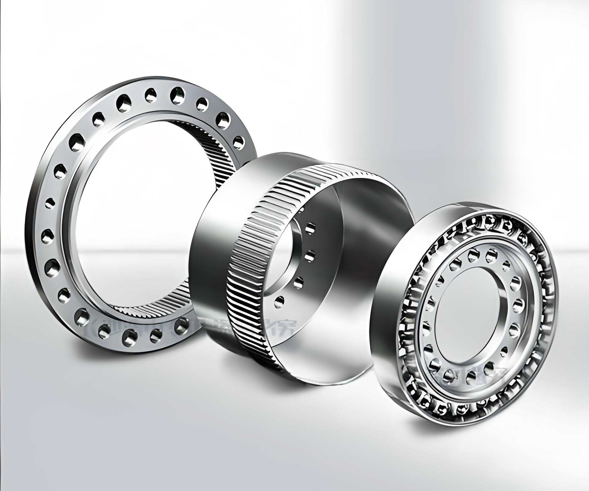
The fundamental components of an oscillating-teeth end-face harmonic gear include an end-face gear, a slot wheel, oscillating teeth, and a wave generator. The oscillating teeth engage with the end-face gear at their front ends to form the front meshing pair, while their rear ends interact with the wave generator to create the rear meshing pair. This arrangement enables smooth power transmission through the oscillatory motion of the teeth, which is orchestrated by the wave generator’s profile. The unique design of this harmonic drive gear allows for significant reduction ratios and compactness, making it ideal for space-constrained environments. However, to ensure efficient operation and minimize dynamic impacts, tooth-face modification becomes essential, particularly for the oscillating teeth and the engaging surfaces of the end-face gear and wave generator.
Tooth-face modification in harmonic drive gears is primarily aimed at reducing the冲击 during the axial reciprocating motion of the oscillating teeth. Without modification, the oscillating teeth would experience abrupt changes in velocity when reversing direction, leading to increased wear, noise, and potential failure. By modifying the tooth faces, the velocity transition can be smoothed, allowing the teeth to decelerate gradually to zero and then accelerate in the opposite direction. This involves rounding off the tooth tips and roots of the wave generator, end-face gear, and oscillating teeth. The modification heights are defined as follows: let \( h_1 \) and \( h_2 \) denote the tooth height segments corresponding to the modification on the rear and front ends of the oscillating teeth, respectively. Similarly, let \( h_{E1} \) and \( h_{E2} \) represent the modification heights for the tooth tip and root of the end-face gear, and \( h_{W1} \) and \( h_{W2} \) for the wave generator. These heights must satisfy specific relationships to ensure proper engagement across the harmonic drive gear system. The conditions are expressed as:
$$ h_{E2} = h_{W1} + h_1 + h_2 $$
$$ h_{W2} = h_{E1} + h_1 + h_2 $$
These equations ensure that the modified surfaces align seamlessly during meshing, preventing interference and promoting continuous contact. The modification process transforms the theoretical tooth profiles into practical ones that account for real-world dynamics, thereby enhancing the overall performance of the harmonic drive gear. In the following sections, I will explore how this modification influences the meshing behavior and total contact area, which are critical for assessing the gear’s strength and longevity.
To analyze the meshing state after tooth-face modification, I employ a geometric model that conceptualizes the engagement between the oscillating teeth and the end-face gear. This model is virtual, representing an idealized tooth profile of the end-face gear that can simultaneously engage with all oscillating teeth. By superimposing the modified oscillating teeth onto this virtual profile according to their relative positions, I construct a comprehensive view of the meshing pair. For instance, consider a harmonic drive gear with a wave generator wave number \( U = 1 \), oscillating teeth count \( Z_O = 6 \), and end-face gear teeth count \( Z_E = 7 \). The expanded view of the meshing pair and its corresponding geometric model reveal that only a subset of oscillating teeth are in active meshing at any given time, while others are in non-working states. Specifically, teeth may be in line contact or surface contact depending on their position relative to the modified segments. This geometric model serves as a foundation for understanding the distribution of contact forces and areas across the harmonic drive gear system.
The motion of oscillating teeth in a modified harmonic drive gear can be divided into distinct phases within one engagement cycle. Initially, when an oscillating tooth enters the modified tip segment of the end-face gear, it experiences line contact, where the meshing area is effectively zero. This phase corresponds to the tooth moving from point A to point B in its path. As the tooth progresses into the unmodified segment of the end-face gear, it transitions to surface contact, resulting in a finite meshing area from point B to point C. Finally, when the tooth engages with the modified root segment of the end-face gear, it reverts to line contact from point C to point D, again with negligible area. This cyclic behavior underscores the importance of modification in smoothing motion transitions, but it also introduces complexities in calculating the total meshing area over time. For harmonic drive gears, accurately capturing these variations is essential for design optimization and failure prevention.
The total meshing area of the working meshing pair in a modified harmonic drive gear exhibits a periodic variation as the slot wheel rotates. This periodicity is characterized by abrupt changes at specific instants: when the total area reaches a minimum, when it reaches a maximum, and when the number of actively meshing teeth increases. For example, if \( Z_O / U \) is an integer, the meshing states are identical across all waves of the wave generator, simplifying the analysis to a single wave. In such cases, the total meshing area \( \sum S_e \) fluctuates between a maximum value \( \sum S_{e \text{max}} \) and a minimum value \( \sum S_{e \text{min}} \), with the period \( T \) depending on whether the end-face gear is fixed (\( T = 2\pi / Z_E \)) or the slot wheel is fixed (\( T = 2\pi / Z_O \)). When \( Z_O / U \) is not an integer, the meshing states differ across waves, but the overall pattern remains similar when all teeth are considered in a unified geometric model. Understanding this规律 is vital for predicting load distribution and ensuring that the harmonic drive gear operates within safe stress limits.
To quantify the total meshing area, I derive formulas for \( \sum S_{e \text{max}} \) and \( \sum S_{e \text{min}} \) based on the structural parameters of the harmonic drive gear. Let \( S_E \) denote the meshing area of a single oscillating tooth when fully engaged with the end-face gear before modification. The total meshing area prior to modification depends on \( Z_O \), \( U \), and \( S_E \), as established in earlier studies. After modification, the meshing area per tooth is reduced due to the trimmed segments, leading to adjusted totals. I consider several cases based on the divisibility of \( Z_O \) by \( U \) and the parity of \( Z_O \).
Case 1: \( Z_O / U \) is an even integer. Before modification, the maximum and minimum total meshing areas are:
$$ \sum S_{E \text{max}} = \frac{Z_O + 2U}{4} S_E $$
$$ \sum S_{E \text{min}} = \frac{Z_O – 2U}{4} S_E $$
After modification, let \( Z_N = Z_O / (2U) \) represent the number of actively meshing teeth per wave at maximum engagement. The meshing area for the first tooth (fully engaged) is reduced by the modification heights:
$$ S_{e1} = S_E – \frac{h_{E1} + h_{E2}}{h} S_E $$
where \( h \) is the total tooth height. The areas for subsequent teeth follow a proportional reduction. Summing over all active teeth and multiplying by the wave number \( U \) yields:
$$ \sum S_{e \text{max}} = \sum S_{E \text{max}} – \frac{U Z_N (h_{E1} + h_{E2})}{h} S_E = \frac{h – 2h_{E1} – 2h_{E2}}{4h} Z_O S_E + \frac{U S_E}{2} $$
The minimum total area occurs when one tooth exits surface contact, leading to:
$$ \sum S_{e \text{min}} = \sum S_{e \text{max}} – U S_{e1} = \frac{h – 2h_{E1} – 2h_{E2}}{4h} Z_O S_E + \frac{h_{E1} + h_{E2} – h}{2h} U S_E $$
Case 2: \( Z_O / U \) is an odd integer. Prior to modification, the totals are:
$$ \sum S_{E \text{max}} = \frac{(Z_O + U)^2}{4Z_O} S_E $$
$$ \sum S_{E \text{min}} = \frac{(Z_O – U)^2}{4Z_O} S_E $$
After modification, with \( Z_N = (Z_O + U) / (2U) \), similar derivations give:
$$ \sum S_{e \text{max}} = \sum S_{E \text{max}} – \frac{U Z_N (h_{E1} + h_{E2})}{h} S_E = \frac{(Z_O + U)^2 S_E}{4Z_O} – \frac{(Z_O + U)(h_{E1} + h_{E2}) S_E}{2h} $$
$$ \sum S_{e \text{min}} = \sum S_{e \text{max}} – U S_{e1} = \frac{(Z_O + U)^2 S_E}{4Z_O} – \frac{[ (Z_O – U)(h_{E1} + h_{E2}) + 2Uh ] S_E}{2h} $$
Case 3: \( Z_O / U \) is not an integer, with \( Z_O \) being even. Before modification:
$$ \sum S_{E \text{max}} = \frac{Z_O + 2}{4} S_E $$
$$ \sum S_{E \text{min}} = \frac{Z_O – 2}{4} S_E $$
After modification, all oscillating teeth are considered in a single geometric model, with \( Z_N = Z_O / 2 \) actively meshing teeth at maximum. The formulas become:
$$ \sum S_{e \text{max}} = \frac{h – 2h_{E1} – 2h_{E2}}{4h} Z_O S_E + \frac{1}{2} S_E $$
$$ \sum S_{e \text{min}} = \frac{h – 2h_{E1} – 2h_{E2}}{4h} Z_O S_E + \frac{2h_{E1} + 2h_{E2} – h}{2h} S_E $$
Case 4: \( Z_O / U \) is not an integer, with \( Z_O \) being odd. Prior to modification:
$$ \sum S_{E \text{max}} = \frac{(Z_O + 1)^2}{4Z_O} S_E $$
$$ \sum S_{E \text{min}} = \frac{(Z_O – 1)^2}{4Z_O} S_E $$
After modification, with \( Z_N = (Z_O + 1) / 2 \), the totals are:
$$ \sum S_{e \text{max}} = \frac{h – 2h_{E1} – 2h_{E2}}{4h} (Z_O + 1) S_E + \frac{Z_O + 1}{4Z_O} S_E $$
$$ \sum S_{e \text{min}} = \frac{h – 2h_{E1} – 2h_{E2}}{4h} Z_O S_E + \frac{h + 2h_{E1} + 2h_{E2}}{4h} S_E + \frac{1 – 3Z_O}{4Z_O} S_E $$
To summarize these cases, I present a table that consolidates the formulas for the total meshing area in modified harmonic drive gears. This table serves as a quick reference for engineers designing such systems, enabling them to select appropriate parameters for optimal performance.
| Case Description | Condition | Maximum Total Meshing Area \( \sum S_{e \text{max}} \) | Minimum Total Meshing Area \( \sum S_{e \text{min}} \) |
|---|---|---|---|
| \( Z_O / U \) even integer | \( Z_N = Z_O / (2U) \) | \( \frac{h – 2h_{E1} – 2h_{E2}}{4h} Z_O S_E + \frac{U S_E}{2} \) | \( \frac{h – 2h_{E1} – 2h_{E2}}{4h} Z_O S_E + \frac{h_{E1} + h_{E2} – h}{2h} U S_E \) |
| \( Z_O / U \) odd integer | \( Z_N = (Z_O + U) / (2U) \) | \( \frac{(Z_O + U)^2 S_E}{4Z_O} – \frac{(Z_O + U)(h_{E1} + h_{E2}) S_E}{2h} \) | \( \frac{(Z_O + U)^2 S_E}{4Z_O} – \frac{[ (Z_O – U)(h_{E1} + h_{E2}) + 2Uh ] S_E}{2h} \) |
| \( Z_O / U \) not integer, \( Z_O \) even | \( Z_N = Z_O / 2 \) | \( \frac{h – 2h_{E1} – 2h_{E2}}{4h} Z_O S_E + \frac{1}{2} S_E \) | \( \frac{h – 2h_{E1} – 2h_{E2}}{4h} Z_O S_E + \frac{2h_{E1} + 2h_{E2} – h}{2h} S_E \) |
| \( Z_O / U \) not integer, \( Z_O \) odd | \( Z_N = (Z_O + 1) / 2 \) | \( \frac{h – 2h_{E1} – 2h_{E2}}{4h} (Z_O + 1) S_E + \frac{Z_O + 1}{4Z_O} S_E \) | \( \frac{h – 2h_{E1} – 2h_{E2}}{4h} Z_O S_E + \frac{h + 2h_{E1} + 2h_{E2}}{4h} S_E + \frac{1 – 3Z_O}{4Z_O} S_E \) |
The derivations above highlight the intricate relationship between geometric parameters and meshing behavior in harmonic drive gears. By incorporating tooth-face modification, the harmonic drive gear achieves smoother motion but at the cost of reduced contact area, which must be accounted for in strength calculations. The formulas provided enable designers to predict the total meshing area under various operating conditions, ensuring that the gear can handle expected loads without excessive stress concentrations. For instance, in high-power applications, maximizing the meshing area during peak engagement is crucial for distributing forces evenly across the teeth, thereby enhancing the longevity of the harmonic drive gear system.
Beyond the mathematical analysis, practical considerations for harmonic drive gears include material selection, lubrication, and manufacturing tolerances. The oscillating-teeth end-face harmonic gear, in particular, benefits from advanced materials like hardened steels or composites to withstand cyclic loading. Lubrication plays a key role in minimizing friction between the modified surfaces, especially during line contact phases where pressure may be high. Manufacturing precision is essential to maintain the specified modification heights, as deviations can alter the meshing characteristics and lead to premature failure. In my experience, computer-aided design and simulation tools are invaluable for optimizing these factors, allowing for iterative refinement of the harmonic drive gear before physical prototyping.
To further illustrate the application of these concepts, consider a harmonic drive gear with parameters \( Z_O = 8 \), \( U = 2 \), \( Z_E = 10 \), \( h = 5 \text{mm} \), \( h_{E1} = 0.5 \text{mm} \), \( h_{E2} = 0.7 \text{mm} \), and \( S_E = 10 \text{mm}^2 \). Since \( Z_O / U = 4 \) is an even integer, I use the formulas from Case 1. First, compute \( Z_N = Z_O / (2U) = 8 / 4 = 2 \). Then, the maximum total meshing area is:
$$ \sum S_{e \text{max}} = \frac{5 – 2(0.5) – 2(0.7)}{4 \times 5} \times 8 \times 10 + \frac{2 \times 10}{2} = \frac{5 – 1 – 1.4}{20} \times 80 + 10 = \frac{2.6}{20} \times 80 + 10 = 10.4 + 10 = 20.4 \text{mm}^2 $$
The minimum total area is:
$$ \sum S_{e \text{min}} = \frac{5 – 1 – 1.4}{20} \times 8 \times 10 + \frac{0.5 + 0.7 – 5}{2 \times 5} \times 2 \times 10 = 10.4 + \frac{-3.8}{10} \times 20 = 10.4 – 7.6 = 2.8 \text{mm}^2 $$
These values indicate that the total meshing area fluctuates between 2.8 mm² and 20.4 mm² during operation, emphasizing the need to design for the minimum area to avoid overloading. Such calculations are integral to the reliability assessment of harmonic drive gears in demanding environments.
In addition to static analysis, dynamic effects in harmonic drive gears warrant attention. The periodic variation in meshing area can induce vibrations, especially if the transition between line and surface contact is not perfectly smooth. Tooth-face modification mitigates this by providing a gradual change in curvature, but residual dynamics may still affect performance. Finite element analysis can model these behaviors, capturing stress distributions and fatigue life predictions. For oscillating-teeth end-face harmonic gears, dynamic simulations often reveal hotspots at the modified segments, guiding further design tweaks. By iterating between analytical formulas and simulations, engineers can achieve a balanced design that maximizes the benefits of harmonic drive gear technology.
The versatility of harmonic drive gears extends to various industries. In robotics, for example, compact harmonic drive gears provide high torque for joint actuators, enabling precise movements in humanoid or industrial robots. The oscillating-teeth end-face variant offers even greater compactness due to its face-gear arrangement, making it suitable for space-constrained robotic arms. In aerospace, harmonic drive gears are used in satellite antenna drives and solar panel deployments, where reliability and weight savings are critical. The modified meshing pairs discussed here enhance these applications by reducing wear and tear, thus extending mission lifetimes. As harmonic drive gear technology evolves, ongoing research focuses on integrating smart materials and sensors for condition monitoring, pushing the boundaries of what these systems can achieve.
From a theoretical perspective, the study of total meshing area in harmonic drive gears contributes to the broader field of gear mechanics. The formulas derived here can be adapted for other types of modified gear systems, such as helical or bevel gears with profile corrections. Moreover, the geometric modeling approach provides a template for analyzing complex engagements in multi-body systems. By publishing these insights, I hope to foster further innovation in harmonic drive gear design, encouraging collaboration between academia and industry to tackle real-world challenges. The harmonic drive gear, with its unique combination of compactness and power density, remains a cornerstone of modern mechanical engineering, and optimizing its meshing characteristics is key to unlocking its full potential.
In conclusion, the total meshing area of modified meshing pairs in oscillating-teeth end-face harmonic gears exhibits a periodic variation influenced by tooth-face modification and structural parameters. Through geometric modeling and analytical derivations, I have established formulas for calculating the maximum and minimum meshing areas under different conditions, summarized in the table above. These findings underscore the importance of modification in smoothing motion transitions and reducing dynamic impacts, while also highlighting the trade-offs in contact area reduction. For engineers designing harmonic drive gears, these insights provide a practical framework for strength assessment and optimization, ensuring robust performance in high-power, high-ratio applications. As the demand for efficient transmission systems grows, continued exploration of harmonic drive gear mechanics will undoubtedly yield further advancements, solidifying their role in future technological landscapes.