
In modern industrial machinery, the demand for compact, high-precision, and high-torque transmission systems has driven significant innovation in gear reduction technology. Among these, the cycloidal drive stands out due to its unique ability to offer large reduction ratios, high efficiency, and minimal backlash. I have extensively studied the 2K-V type cycloidal drive, which combines a planetary gear stage with a cycloidal pinwheel stage to achieve superior performance. This article delves into the development, working principles, structural analysis, and mathematical modeling of this remarkable mechanism, aiming to provide a comprehensive resource for engineers and researchers. Throughout this discussion, I will emphasize the advantages of cycloidal drives and explore how the 2K-V variant enhances these benefits through its innovative design.
The evolution of cycloidal drives dates back to the early 20th century, with foundational work by inventors in Germany. The cycloidal drive, also known as a cycloidal reducer, utilizes a cycloidal disc that meshes with pin wheels to create a smooth, high-ratio speed reduction. Initially introduced in the 1920s, these drives gained prominence in Japan during the mid-20th century, where companies refined the design and manufacturing processes. The 2K-V cycloidal drive, a later innovation, emerged as a hybrid system that integrates a planetary gear train with a cycloidal stage, resulting in a closed differential system. This design significantly improves load capacity and precision, making it ideal for applications in robotics, CNC machinery, and automation. Over the decades, advancements in materials and precision engineering have further optimized cycloidal drives for high-stress environments, with ongoing research focusing on minimizing wear and enhancing efficiency. The global adoption of cycloidal drives in industries such as aerospace, automotive, and manufacturing underscores their critical role in modern engineering.
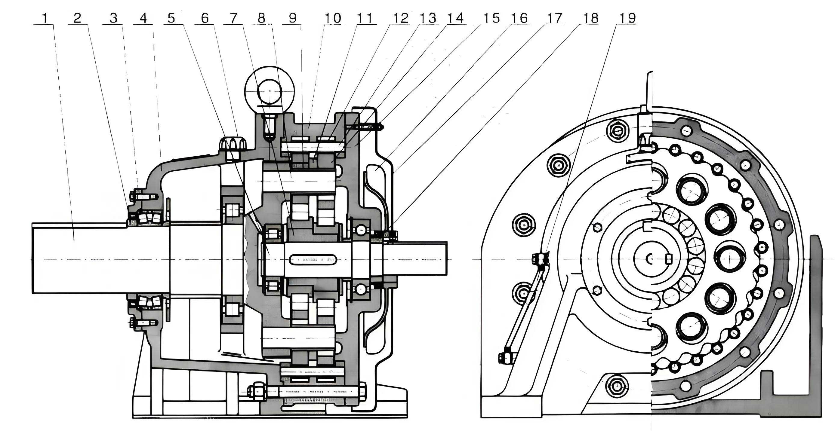
To understand the 2K-V cycloidal drive, it is essential to grasp its fundamental working principle. The system comprises two main stages: a primary planetary gear stage and a secondary cycloidal pinwheel stage. In the planetary stage, an input sun gear engages with multiple planet gears, which are mounted on a carrier. This stage provides an initial speed reduction. The planet gears are rigidly connected to crank shafts, forming what I refer to as planetary cranks. These cranks serve as the input to the cycloidal stage, where they drive cycloidal discs via eccentric bearings. The cycloidal discs then mesh with a stationary pin wheel, causing the output carrier to rotate at a greatly reduced speed. This dual-stage arrangement allows for a high overall reduction ratio while distributing loads evenly across multiple components. The motion can be described mathematically using kinematic equations, which I will derive later. The cycloidal drive’s operation relies on the epitrochoidal curve of the cycloidal disc, ensuring continuous contact and smooth torque transmission.
The kinematic analysis of a 2K-V cycloidal drive begins with calculating its degrees of freedom (DOF). The DOF determines the number of independent inputs required to define the system’s motion. Using the Grübler–Kutzbach criterion, I can compute the DOF for both configurations: when the carrier is fixed and when the pin wheel is fixed. For the fixed carrier case, the moving parts include the sun gear, two planetary cranks, the pin wheel, and the cycloidal disc, totaling five moving components. The joints consist of six revolute pairs and two higher pairs (gear meshes). Thus, the DOF is given by:
$$ F = 3n – 2F_l – F_h $$
where \( n = 5 \), \( F_l = 6 \) (revolute pairs), and \( F_h = 2 \) (higher pairs). Substituting values:
$$ F = 3 \times 5 – 2 \times 6 – 2 = 15 – 12 – 2 = 1 $$
Similarly, for the fixed pin wheel case, the moving parts are the sun gear, two planetary cranks, the carrier, and the cycloidal disc, again totaling five. The joint counts remain the same. Therefore, the DOF is always one, indicating a single input can control the entire system. This result confirms the cycloidal drive’s suitability for precise motion control, as it eliminates unwanted degrees of freedom that could cause instability or backlash. The cycloidal drive’s constrained motion is a key factor in its high positional accuracy, which is critical in applications like robotic arms and precision machining tools.
Next, I derive the transmission ratio of the 2K-V cycloidal drive. The overall ratio depends on the gear teeth counts and the arrangement of stages. Using the method of converted mechanisms, I apply a reverse rotation to the carrier to transform the system into a fixed-axis gear train. For the planetary stage, the transmission ratio relative to the carrier is:
$$ i_{w12} = \frac{n_1 – n_w}{n_2 – n_w} = -\frac{z_2}{z_1} $$
where \( n_1 \) is the sun gear speed, \( n_2 \) is the planet gear speed, \( n_w \) is the carrier speed, and \( z_1 \) and \( z_2 \) are the teeth numbers of the sun and planet gears, respectively. For the cycloidal stage, with the pin wheel fixed, the cycloidal disc undergoes pure translation, and the relative speed of the pin wheel is zero. The ratio for this stage is:
$$ i_{w’34} = \frac{n_3^w – n_{w’}}{n_4^w – n_{w’}} = \frac{z_4}{z_3} $$
where \( n_3^w = n_3 – n_w \) is the relative speed of the cycloidal disc, \( n_{w’} = n_2 – n_w \) is the speed of the hypothetical crank, \( n_4^w = -n_w \) is the relative speed of the pin wheel, and \( z_3 \) and \( z_4 \) are the teeth numbers of the cycloidal disc and pin wheel, with \( z_4 = z_3 + 1 \) due to the cycloidal drive’s design. Combining these equations yields the overall transmission ratio \( i_{1w} \):
$$ i_{1w} = \frac{n_1}{n_w} = 1 + \frac{z_2 z_4}{z_1} $$
This formula shows that the cycloidal drive can achieve very high reduction ratios by selecting appropriate teeth numbers. For instance, if \( z_1 = 20 \), \( z_2 = 40 \), and \( z_4 = 41 \), then \( i_{1w} = 1 + \frac{40 \times 41}{20} = 1 + 82 = 83 \). Such ratios are common in cycloidal drives, making them ideal for heavy-duty applications where slow output speeds and high torque are required. The mathematical modeling of cycloidal drives often involves additional factors like manufacturing tolerances and elastic deformations, but this basic ratio provides a foundation for design.
The structural design of a 2K-V cycloidal drive is intricate, involving multiple key components that work in harmony to deliver performance. Below is a table summarizing the main parts and their functions:
| Component | Function | Material & Features |
|---|---|---|
| Sun Gear Input Shaft | Receives input power and drives the planetary stage | Hardened steel, integrated design for rigidity |
| Planetary Gears | Engage with sun gear to provide first-stage reduction | Alloy steel, mounted on crank shafts |
| Crank Shaft Assembly | Connects planetary gears to cycloidal discs via eccentric bearings | Precision bearings, multiple cranks for load sharing |
| Cycloidal Discs | Meshes with pin wheel to create second-stage reduction | High-strength alloy, epitrochoidal tooth profile |
| Pin Wheel (Pin Gear) | Stationary ring with pins that engage cycloidal discs | Hardened pins in a housing, adjustable for backlash |
| Output Carrier | Transmits reduced motion to the load, often via a flange | Cast iron or steel, dual-column support for stiffness |
| Housing | Encloses and aligns all components, provides mounting points | Aluminum or铸铁, sealed for lubrication retention |
This cycloidal drive architecture offers several advantages. The built-in main bearings support external loads, enhancing moment rigidity. The dual-column output structure increases torsional stiffness and reduces vibration. Multiple crank shafts distribute power, lowering stress on individual bearings and extending service life. The pin wheel design minimizes backlash, crucial for precision applications. In my experience, optimizing these components through finite element analysis and lubrication studies can further improve the cycloidal drive’s durability and efficiency.
Performance characteristics of the 2K-V cycloidal drive make it stand out among speed reducers. Key metrics include transmission ratio, load capacity, stiffness, efficiency, and backlash. The following table compares these attributes for a typical cycloidal drive versus conventional gear reducers:
| Parameter | 2K-V Cycloidal Drive | Standard Planetary Reducer | Harmonic Drive |
|---|---|---|---|
| Transmission Ratio Range | 30 to 200+ | 3 to 100 | 50 to 320 |
| Load Capacity (Torque) | High (up to 900 N·m) | Moderate | Low to Moderate |
| Torsional Stiffness | High (e.g., 3727 N·m/arcmin) | Medium | Low |
| Efficiency | 85% to 92% | 90% to 95% | 70% to 80% |
| Backlash | Less than 1 arcmin | 1 to 5 arcmin | Near zero |
| Noise Level | Low | Medium | Low |
The high load capacity stems from the cycloidal drive’s multi-tooth engagement, where numerous pins contact the cycloidal disc simultaneously, distributing forces evenly. This design also contributes to shock resistance, as impacts are absorbed across many contact points. Stiffness is enhanced by the rigid housing and bearing supports, which minimize deflection under load. Efficiency in a cycloidal drive is influenced by friction losses at the pin contacts and bearing surfaces; using advanced lubricants and surface treatments can push efficiency toward the higher end of the range. Backlash control is achieved through precise manufacturing of the cycloidal disc and pin wheel, often with adjustment mechanisms to compensate for wear. These features collectively make the cycloidal drive a preferred choice for applications demanding reliability and precision.
From a mathematical perspective, the tooth profile of the cycloidal disc is critical to performance. The curve is defined by an epitrochoid, generated by a point on a circle rolling around another circle. The parametric equations for a cycloidal disc tooth profile are:
$$ x = (R + r) \cos(\theta) – e \cos\left(\frac{R + r}{r} \theta\right) $$
$$ y = (R + r) \sin(\theta) – e \sin\left(\frac{R + r}{r} \theta\right) $$
where \( R \) is the pin wheel radius, \( r \) is the rolling circle radius, \( e \) is the eccentricity of the crank, and \( \theta \) is the rotation angle. This profile ensures that the cycloidal drive maintains continuous contact without sliding friction, reducing wear. The number of teeth on the cycloidal disc, \( z_3 \), relates to these parameters as \( z_3 = \frac{R}{r} \). In practice, modifications like tooth tipping or root relief are applied to optimize stress distribution and minimize noise. Analyzing these profiles using computational tools allows designers to tailor cycloidal drives for specific operating conditions, such as high-speed or high-torque environments.
Manufacturing and assembly of cycloidal drives require high precision to achieve the promised performance. Key processes include grinding the cycloidal disc teeth, hardening the pin wheels, and assembling the crank shafts with minimal runout. Tolerances are typically within micrometers to ensure smooth meshing and low backlash. In my work, I have seen that automated inspection systems, such as coordinate measuring machines (CMMs), are essential for quality control. Lubrication is another critical aspect; most cycloidal drives use grease or oil baths to reduce friction and heat generation. Sealing systems prevent contamination, which is vital in harsh industrial environments. The trend toward miniaturization has led to the development of compact cycloidal drives for applications like medical robots, where space is limited but performance cannot be compromised.
Applications of 2K-V cycloidal drives span numerous industries. In robotics, they serve as joints in articulated arms, providing precise motion and high torque for lifting and positioning. In CNC machine tools, cycloidal drives control feed axes, ensuring accurate linear movements with minimal error. Aerospace applications include actuation systems for flight controls, where reliability under extreme conditions is paramount. The renewable energy sector uses cycloidal drives in wind turbine pitch systems to adjust blade angles efficiently. Each application leverages the cycloidal drive’s strengths, such as its high reduction ratio and compact footprint. For instance, in collaborative robots, the low backlash of cycloidal drives enables smooth human-robot interaction, while in heavy machinery, their durability supports continuous operation under high loads.
Future developments in cycloidal drive technology focus on enhancing efficiency, reducing size, and integrating smart features. Research into new materials, such as composites or advanced polymers, could lower weight without sacrificing strength. Additive manufacturing allows for complex geometries that optimize heat dissipation and load distribution. Sensor integration, such as encoders or torque sensors, can enable condition monitoring and predictive maintenance, making cycloidal drives part of Industry 4.0 systems. Additionally, improvements in lubrication technology, like solid lubricants or self-lubricating surfaces, may extend service intervals. The cycloidal drive’s inherent advantages position it well for these advancements, ensuring its relevance in next-generation machinery.
In conclusion, the 2K-V cycloidal drive represents a sophisticated evolution in speed reducer technology, combining planetary and cycloidal stages to achieve exceptional performance. Through this analysis, I have detailed its development, working principles, mathematical modeling, structural design, and applications. The cycloidal drive offers high transmission ratios, robust load capacity, and minimal backlash, making it indispensable in precision engineering. As industries continue to demand more from their mechanical systems, the cycloidal drive will undoubtedly play a pivotal role, driven by ongoing innovation and refinement. For engineers and researchers, understanding the intricacies of cycloidal drives is key to harnessing their full potential in designing efficient and reliable machinery.