
In my extensive experience with heavy machinery maintenance, particularly in port environments, the reliability of drive systems is paramount for operational efficiency. Among these, the cycloidal drive, often employed in the slewing mechanisms of portal cranes, presents unique challenges due to its precision and demanding working conditions. This article delves into a detailed analysis of recurrent failures in a GQ25T portal crane’s cycloidal drive, specifically focusing on issues like abnormal noise and loss of transmission power. Through systematic investigation, I identified critical flaws in the forced lubrication system and implemented enhancements that ensured continuous lubrication during both left and right slewing motions. Furthermore, the integration of a pressure sensing system for lubrication预警 has significantly improved the operational reliability of the cycloidal drive. The following sections provide an in-depth exploration of the故障成因,改进对策, and the underlying principles, supported by technical formulas and summary tables to encapsulate the findings.
The cycloidal drive, a type of precision speed reducer, is renowned for its high torque capacity and compact design. In the context of portal cranes, it is typically used in the slewing mechanism to facilitate smooth rotational movement. The core operation of a cycloidal drive involves the meshing of cycloidal discs with pin gears. The fundamental kinematics can be described using mathematical relationships. For instance, the speed reduction ratio (i) of a standard cycloidal drive is given by:
$$ i = \frac{Z_p}{Z_p – Z_c} $$
where \( Z_p \) is the number of pin teeth (pins) on the stationary ring and \( Z_c \) is the number of lobes on the cycloidal disc. In the specific case of the GQ25T crane’s减速箱, the ratio is i=87, indicating a substantial reduction from the motor’s high speed to the desired output torque. This high ratio is achieved through the eccentric motion of the cycloidal discs. The force transmission within the cycloidal drive can be modeled by considering the contact forces between the cycloidal disc and the pins. The torque transmission efficiency (η) is influenced by factors such as friction and lubrication, and can be approximated as:
$$ \eta = 1 – \frac{\mu \cdot F_n \cdot r}{T_{in}} $$
where \( \mu \) is the coefficient of friction, \( F_n \) is the normal force at the contact points, \( r \) is the effective radius, and \( T_{in} \) is the input torque. Poor lubrication directly increases \( \mu \), leading to a drop in η and manifesting as transmission power loss.
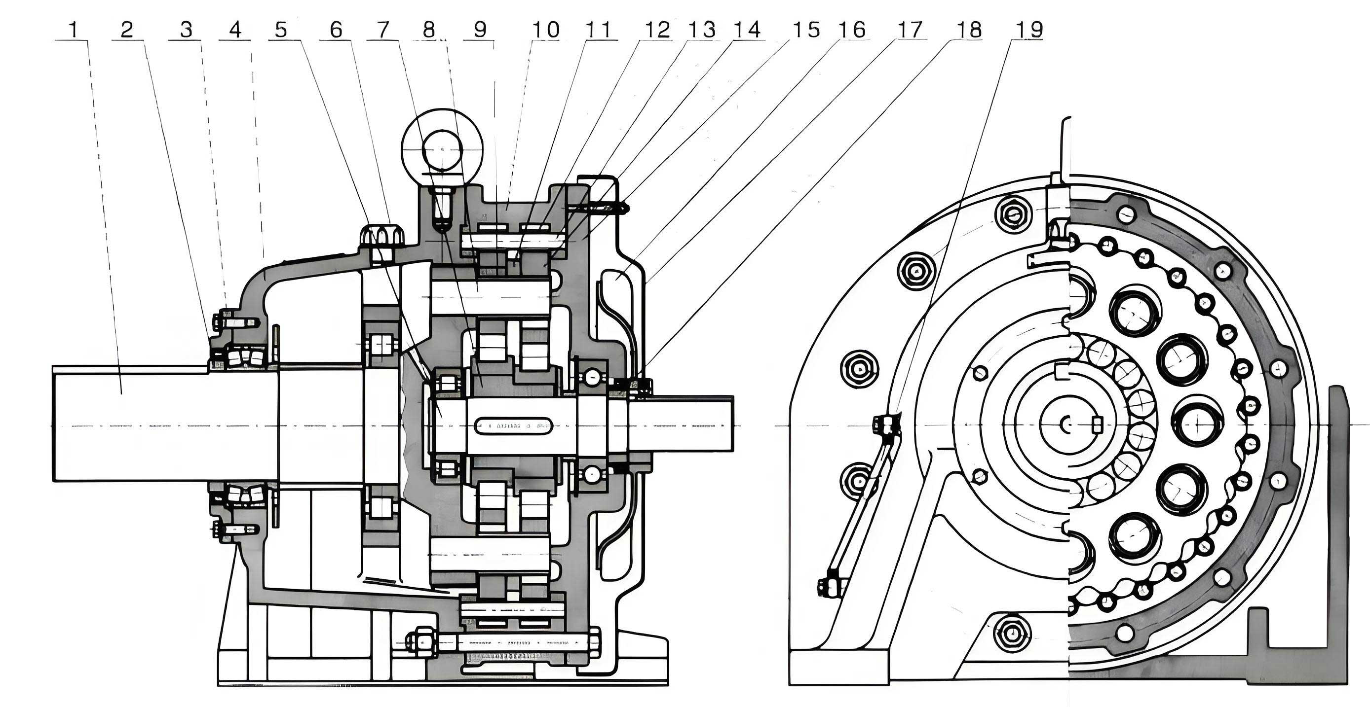
The structural complexity of the cycloidal drive necessitates meticulous lubrication. As illustrated in the accompanying figure, key components like the cycloidal discs, pin teeth, eccentric bearings, and output shaft bearings are all interdependent. In the立式安装 of the GQ25T crane, the forced lubrication system is critical. This system typically uses a gear pump driven by an AC motor to circulate oil from a sump to the high-speed input shaft bearings and the pin gear mesh. The flow rate (Q) required for adequate lubrication can be estimated using:
$$ Q = \frac{P_{loss}}{\rho \cdot c \cdot \Delta T} $$
where \( P_{loss} \) is the power loss due to friction (which increases with poor lubrication), \( \rho \) is the oil density, \( c \) is the specific heat capacity, and \( \Delta T \) is the allowable temperature rise. A failure in maintaining this flow leads to accelerated wear.
Upon dissecting the故障成因, I observed that the original lubrication system had a fundamental design flaw. The lubrication motor was electrically interlocked only with the left-slewing contactor. Consequently, lubrication only occurred during left slewing operations. During right slewing, the cycloidal drive’s upper components, particularly the input shaft bearings and pin teeth, were deprived of forced oil flow, relying only on residual oil or ineffective splash. This partial lubrication over years of operation, with the crane frequently alternating between left and right turns, led to predictable failure modes. The predominant issues are summarized in the table below:
| Failure Mode | Affected Components | Root Cause | Observation from Dissected Units |
|---|---|---|---|
| Abnormal “squeaking” noise | Pin teeth (pins and sleeves), eccentric bearings | Insufficient lubrication leading to dry friction | Visible scoring and wear on pin surfaces; metallic debris in oil |
| Transmission power loss | Cycloidal discs,销轴销套 (output pin sleeves) | Increased friction, wear, and loss of mechanical efficiency | Worn cycloidal disc lobes; loose or damaged pin sleeves | Overheating | Entire gearbox housing | Inadequate heat dissipation due to low oil circulation | Discoloration of components; degraded oil viscosity |
| Catastrophic seizure | Pin teeth or bearings | Complete lubrication failure | Fused or broken pins; seized eccentric bearings |
The statistical correlation between lubrication and cycloidal drive failure is striking. Studies suggest over 80% of减速箱 failures stem from lubrication issues. In this case, the intermittent operation of the lubrication motor, caused by burnt contacts in the control contactor, exacerbated the problem. The electrical fault created a scenario where even during designated left-slewing cycles, the lubrication was sporadic. This inconsistency meant that the cycloidal drive often operated under boundary lubrication conditions, vastly accelerating wear. The wear rate (W) in such conditions can be modeled by Archard’s wear equation:
$$ W = k \frac{F_n \cdot s}{H} $$
where \( k \) is the wear coefficient (highly dependent on lubrication regime), \( F_n \) is the normal load, \( s \) is the sliding distance, and \( H \) is the material hardness. Poor lubrication increases \( k \) exponentially, leading to rapid material removal from critical components like the pin teeth of the cycloidal drive.
To address these systemic issues, a comprehensive改进对策 was designed and implemented. The core principle was to decouple the lubrication system’s operation from the directional control of the slewing mechanism. The primary modification was in the electrical control circuit. The power supply for the lubrication motor was shifted from being controlled by the left-slewing contactor to being connected directly to the main power supply of the slewing mechanism. This simple yet effective change ensured that whenever the portal crane’s slewing mechanism was energized—regardless of rotation direction—the forced lubrication pump would operate. This guaranteed全过程润滑 for the cycloidal drive.
However, ensuring the pump runs is only one part of the solution. The health of the entire lubrication circuit—including the pump itself, filters, and pipes—is crucial. Therefore, a second layer of protection was added: a lubrication pressure sensing and预警 system. A pressure transducer was installed at the output side of the oil filter. This sensor continuously monitors the lubricant pressure. The system is designed with a threshold pressure \( P_{min} \), derived from the pump’s rated performance and system hydraulic resistance. If the sensed pressure \( P_{sens} \) falls below this threshold, it triggers an audible and visual alarm in the operator’s cab. The logic can be represented as:
$$ \text{Alarm Trigger} = \begin{cases}
\text{Active}, & \text{if } P_{sens} < P_{min} \\
\text{Inactive}, & \text{if } P_{sens} \geq P_{min}
\end{cases} $$
This预警 allows for proactive maintenance, preventing the cycloidal drive from operating under low-pressure conditions indicative of a clogged filter, pump wear, or motor failure. The table below contrasts the old and new system configurations:
| Aspect | Original Lubrication System | Improved Lubrication System |
|---|---|---|
| Control Logic | Interlocked with LEFT slewing command only. | Independent; runs whenever slewing mechanism is powered. |
| Lubrication Coverage | Only during left rotation. Right rotation caused lubrication starvation for upper cycloidal drive components. | Continuous during all slewing operations, ensuring full-component lubrication. |
| Monitoring | None. Failures were only detected after symptoms (noise, power loss) appeared. | Real-time pressure monitoring with operator预警 for low pressure. |
| Maintenance Approach | Reactive – repair after cycloidal drive failure. | Proactive – address lubrication system issues before they damage the cycloidal drive. |
| Expected Impact on Wear Coefficient (k) | High and variable due to intermittent/boundary lubrication. | Low and stable due to continuous film lubrication. |
The performance of a well-lubricated cycloidal drive can be further analyzed by considering the elastohydrodynamic lubrication (EHL) film thickness between the cycloidal disc and the pin teeth. The minimum film thickness \( h_{min} \) can be estimated using the Dowson-Higginson formula:
$$ h_{min} = 2.65 \frac{R^{0.43} (\eta_0 u)^{0.7}}{\alpha^{0.54} E’^{0.03} W^{0.13}} $$
where \( R \) is the effective radius of curvature, \( \eta_0 \) is the dynamic viscosity at atmospheric pressure, \( u \) is the entraining velocity, \( \alpha \) is the pressure-viscosity coefficient, \( E’ \) is the equivalent Young’s modulus, and \( W \) is the load per unit width. The improvements ensure that parameters like \( \eta_0 \) (maintained by clean, cool oil) and \( u \) (consistent due to continuous pump operation) support the formation of a protective film, drastically reducing wear in the cycloidal drive.
The implementation of these改进对策 required careful planning. The electrical modification involved rerouting cables and verifying the contactor ratings to handle continuous operation. The pressure sensor installation necessitated a T-fitting in the lubrication line and calibration of the alarm threshold \( P_{min} \). Post-modification, the cycloidal drive was subjected to extended monitoring. The results were unequivocal: the periodic “squeaking” noises ceased entirely. Oil analysis from subsequent定期维护 showed a marked decrease in metallic particle counts. The operational lifespan of the cycloidal drive has been extended significantly, moving from the previous 2-3 year failure cycle to a projected lifespan aligned with the manufacturer’s design specifications under proper maintenance.
In conclusion, the故障分析 of the GQ25T portal crane’s cycloidal drive underscores a critical lesson: the reliability of precision mechanical systems like the cycloidal drive is intrinsically tied to the robustness of their ancillary support systems, especially lubrication. The original design oversight, which linked lubrication to a single direction of motion, created a latent failure mode that manifested over time. By re-engineering the control logic to ensure unconditional lubrication during all slewing operations and incorporating a pressure-based预警 system, we transformed the maintenance paradigm from reactive to proactive. This holistic approach not only safeguards the cycloidal drive but also enhances overall equipment availability and reduces lifecycle costs. The formulas and tables presented herein provide a framework for analyzing and improving similar drive systems in heavy industrial applications. The success of this project reaffirms that attention to systemic interdependencies—where the health of the cycloidal drive is monitored through its lubrication pressure—is key to achieving operational excellence in demanding port environments.