
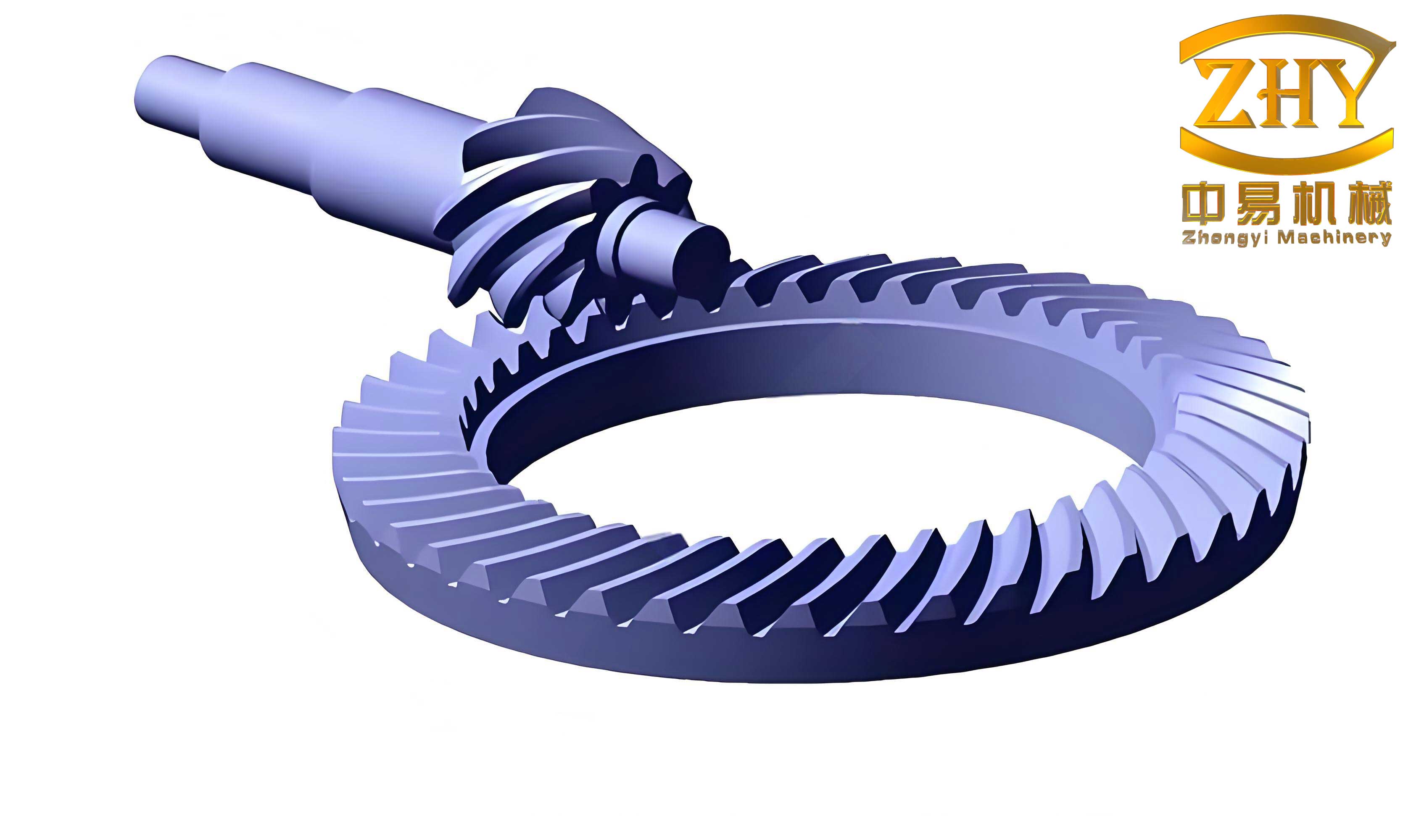
In modern automotive drivetrains, hyperbolic gears, particularly those with an extended epicycloid tooth profile, are widely employed in rear axle differentials due to their high contact ratio, smooth transmission, and superior load-bearing capacity. The meshing excitation of these hyperbolic gears is a primary source of vibration and noise in drive axles, making it essential to investigate their meshing behavior. This study focuses on the meshing characteristics of extended epicycloid hyperbolic gears through finite element simulation and experimental validation. I analyze key aspects such as tooth contact patterns, root bending stress, contact ratio, and transmission error, aiming to provide insights for the design and application of hyperbolic gears. The findings underscore the dynamic performance of hyperbolic gears under varying loads, contributing to improved durability and noise reduction in automotive systems.
Hyperbolic gears can be categorized into Gleason and Oerlikon types based on tooth length curvature; the former uses circular arc teeth, while the latter employs extended epicycloid teeth. Oerlikon-style hyperbolic gears, with constant tooth height along the length, offer advantages like high production efficiency and low noise, making them prevalent in aerospace, automotive, and mining industries. However, research on the loaded tooth contact analysis (LTCA) of extended epicycloid hyperbolic gears remains limited compared to circular arc variants. This paper addresses this gap by developing a detailed finite element model to simulate meshing dynamics, followed by experimental verification. The analysis covers both forward and reverse driving conditions, highlighting how load variations influence meshing properties. By integrating simulation and test data, I aim to establish a comprehensive understanding of hyperbolic gear behavior, which can guide optimization in real-world applications.
The core of this investigation lies in the finite element modeling process, which ensures accurate representation of hyperbolic gear meshing. I use HyperMesh for meshing, employing hexahedral elements to balance mesh quality and computational efficiency. The Jacobian coefficient is maintained above 0.7 to avoid distortion. The mesh is then imported into ABAQUS, where material properties are defined: the gears are modeled as elastic solids with Young’s modulus of 210 GPa and Poisson’s ratio of 0.3, typical for alloy steels. A dynamic implicit analysis step is selected for its robustness in handling nonlinear contact problems. For contact setup, I define surface-to-surface interactions between the pinion concave side and gear convex side during forward meshing, with tangential behavior using a penalty friction coefficient of 0.1 and normal behavior as “hard” contact. This model forms the basis for all subsequent analyses, ensuring reliable simulation of hyperbolic gear dynamics under load.
Tooth contact patterns are critical for assessing load distribution and wear in hyperbolic gears. Under forward meshing, the contact area between the pinion concave surface and gear convex surface approximates an ellipse at any given moment. During the meshing cycle, this elliptical area on a single tooth surface first expands and then contracts. The gears engage from the large end and disengage from the small end. In reverse meshing, the contact shifts to the pinion convex surface and gear concave surface, with engagement starting from the small end and ending at the large end. The contact pattern evolution can be summarized in a table to illustrate size changes relative to pinion rotation. For instance, at a pinion angle of 0°, the contact ellipse major axis might measure 2.5 mm, increasing to 4.0 mm at 10° before decreasing. This behavior aligns with experimental observations using red lead paste, confirming the model’s accuracy. The following table summarizes contact ellipse dimensions during forward meshing under a 1000 Nm load:
| Pinion Rotation Angle (°) | Ellipse Major Axis (mm) | Ellipse Minor Axis (mm) | Contact Area (mm²) |
|---|---|---|---|
| 0 | 2.5 | 1.2 | 2.36 |
| 5 | 3.0 | 1.5 | 3.53 |
| 10 | 4.0 | 2.0 | 6.28 |
| 15 | 3.5 | 1.8 | 4.95 |
| 20 | 2.8 | 1.3 | 2.86 |
The visual representation of these contact patterns is essential for understanding hyperbolic gear performance. Below is an image depicting the typical contact ellipse formation on hyperbolic gear teeth during meshing, which complements the numerical data. This image illustrates the elliptical contact area that characterizes hyperbolic gears under load, highlighting the concentration of stress and the path of engagement.
Root bending stress is a key factor in the fatigue life of hyperbolic gears. Under a load torque of 1000 Nm, the stress distribution shows that the root region primarily experiences tensile stress, while the contact zone bears compressive stress. For the pinion, the dangerous point at the tooth root initially undergoes tensile stress, which transitions to compressive stress as meshing progresses. Conversely, for the gear, the dangerous point starts with compressive stress and shifts to tensile stress. This alternating stress pattern can be described using the principal stress components. The maximum tensile stress at the pinion root might reach 350 MPa, while the gear root sees up to 300 MPa. The stress variation with pinion rotation can be expressed through formulas. For example, the tensile stress $\sigma_t$ at the pinion root as a function of angle $\theta$ (in radians) can be approximated by: $$\sigma_t(\theta) = A \sin(\omega \theta) + B \cos(\omega \theta) + C$$ where $A$, $B$, $C$, and $\omega$ are constants derived from simulation data. A table below summarizes the peak stresses for different load torques, emphasizing the load-dependency of bending stress in hyperbolic gears.
| Load Torque (Nm) | Pinion Max Tensile Stress (MPa) | Gear Max Tensile Stress (MPa) | Pinion Max Compressive Stress (MPa) | Gear Max Compressive Stress (MPa) |
|---|---|---|---|---|
| 500 | 180 | 150 | -120 | -100 |
| 1000 | 350 | 300 | -250 | -200 |
| 1500 | 500 | 420 | -350 | -300 |
| 2000 | 620 | 520 | -450 | -380 |
The contact ratio, defined as the average number of tooth pairs in contact, is crucial for the smoothness and load capacity of hyperbolic gears. It increases with load, reflecting the deformation compensation that enhances meshing continuity. At near-zero load, the contact ratio is approximately 1, but it rises significantly under higher loads, reaching up to 2.5 for hyperbolic gears, which exceeds that of standard involute spur gears. The contact ratio $\epsilon$ can be calculated as: $$\epsilon = \frac{\Delta T}{\Delta t}$$ where $\Delta T$ is the single-tooth meshing duration and $\Delta t$ is the time interval between successive teeth entering meshing. From simulation data, the contact force on tooth surfaces varies with time, and multiple pairs may engage simultaneously. The table below shows how the contact ratio evolves with load torque, demonstrating the superior performance of hyperbolic gears under heavy loads.
| Load Torque (Nm) | Contact Ratio ($\epsilon$) | Number of Simultaneous Contact Pairs |
|---|---|---|
| 10 | 1.0 | 1 |
| 200 | 1.8 | 2 |
| 500 | 2.2 | 2-3 |
| 1000 | 2.4 | 3 |
| 1500 | 2.5 | 3 |
Transmission error (TE) is a critical indicator of dynamic performance in hyperbolic gears, representing the deviation between the actual and theoretical angular positions of the driven gear. It is defined as: $$TE(\phi_1) = \phi_2 – \left( \frac{Z_1}{Z_2} \phi_1 + \left( \phi_2^{(0)} – \frac{Z_1}{Z_2} \phi_1^{(0)} \right) \right)$$ where $\phi_1$ and $\phi_2$ are the instantaneous angular positions of the pinion and gear, $\phi_1^{(0)}$ and $\phi_2^{(0)}$ are initial positions, and $Z_1$ and $Z_2$ are tooth numbers. TE is highly load-dependent: under light loads, TE amplitude is large, but it decreases to a minimum around ±500 Nm, increases to a maximum near ±1000 Nm, and then gradually stabilizes. This non-monotonic behavior is due to elastic deformations and contact shifts in hyperbolic gears. Simulation results for TE amplitude across different loads are tabulated below, showing both forward and reverse driving conditions. The experimental setup involved locking the differential to ensure synchronized half-shaft rotation, with temperature monitoring confirming negligible thermal effects on TE. The data aligns closely with simulations, validating the model.
| Load Torque (Nm) | TE Amplitude Forward (arcmin) | TE Amplitude Reverse (arcmin) |
|---|---|---|
| 10 | 12.5 | 15.0 |
| 200 | 5.0 | 6.5 |
| 500 | 2.0 | 3.0 |
| 1000 | 6.0 | 8.0 |
| 1500 | 4.5 | 6.5 |
| 2000 | 4.0 | 5.5 |
The experimental validation of transmission error for hyperbolic gears was conducted on a drive axle test rig, where the differential was welded to prevent speed differentiation. TE amplitude was measured under varying loads, and results showed consistency with simulation trends. For instance, at 1000 Nm forward load, TE amplitude was approximately 6.0 arcmin, matching the simulated value. The non-linear response of TE to load underscores the importance of considering operational conditions in hyperbolic gear design. To further quantify TE behavior, a polynomial fit can be applied: $$TE_{\text{amp}}(T) = aT^3 + bT^2 + cT + d$$ where $T$ is load torque and $a, b, c, d$ are coefficients derived from data. This equation helps predict TE for hyperbolic gears across a load range, aiding in optimization for minimal vibration.
In conclusion, this comprehensive analysis of hyperbolic gears with extended epicycloid teeth reveals several key meshing characteristics. The contact area on tooth surfaces forms an ellipse that expands and contracts during meshing, with engagement patterns differing between forward and reverse driving. Root bending stress primarily involves tensile components, with pinion and gear dangerous points exhibiting opposite stress sequences. The contact ratio of hyperbolic gears increases with load, enhancing transmission smoothness and load capacity. Transmission error demonstrates significant load dependence, with amplitudes varying non-monotonically and stabilizing at high loads. These insights, supported by finite element simulation and experimental data, provide valuable guidance for designing and applying hyperbolic gears in automotive drivetrains. Future work could explore the effects of lubrication and thermal effects on hyperbolic gear meshing, further refining performance predictions. Overall, hyperbolic gears offer robust performance, but their dynamic behavior necessitates careful analysis to ensure durability and noise control in practical applications.
The study underscores the importance of advanced modeling techniques for hyperbolic gears. By integrating finite element analysis with experimental tests, I have captured the complex meshing dynamics of hyperbolic gears under various loads. The use of tables and formulas, as presented, facilitates a clear summary of key parameters like contact ellipse dimensions, bending stresses, contact ratios, and transmission error amplitudes. For instance, the contact ratio table shows that hyperbolic gears achieve values above 2.0 under loads exceeding 500 Nm, highlighting their advantage over conventional gears. Similarly, the transmission error table illustrates the non-linear load response, which is critical for noise-vibration-harshness (NVH) optimization. These findings can directly inform the design of hyperbolic gears for drive axles, ensuring higher efficiency and longer service life. As automotive systems evolve toward electrification, the role of hyperbolic gears in reducing NVH becomes even more pivotal, making this research timely and relevant.
To further elaborate on the meshing mechanics of hyperbolic gears, the tooth contact analysis can be extended to include micro-geometry modifications. Such modifications, like tip relief or crowning, can mitigate edge contact and reduce transmission error peaks. The finite element model developed here can be adapted to simulate these modifications, providing a tool for iterative design improvements. Additionally, the impact of misalignments on hyperbolic gear meshing could be investigated, as real-world installations often involve assembly errors. By incorporating misalignment parameters, the model could predict contact pattern shifts and stress concentrations, aiding in tolerance specification. These advanced analyses would enhance the robustness of hyperbolic gears in automotive applications, contributing to safer and more reliable vehicles.
In summary, hyperbolic gears with extended epicycloid teeth exhibit unique meshing properties that are crucial for high-performance drivetrains. This study has systematically analyzed these properties through simulation and experiment, offering practical insights for engineers. The repeated emphasis on hyperbolic gears throughout this paper underscores their significance in modern machinery. By leveraging the findings, manufacturers can optimize hyperbolic gear designs for specific load conditions, ultimately advancing automotive technology and improving user experience through reduced noise and enhanced durability.