
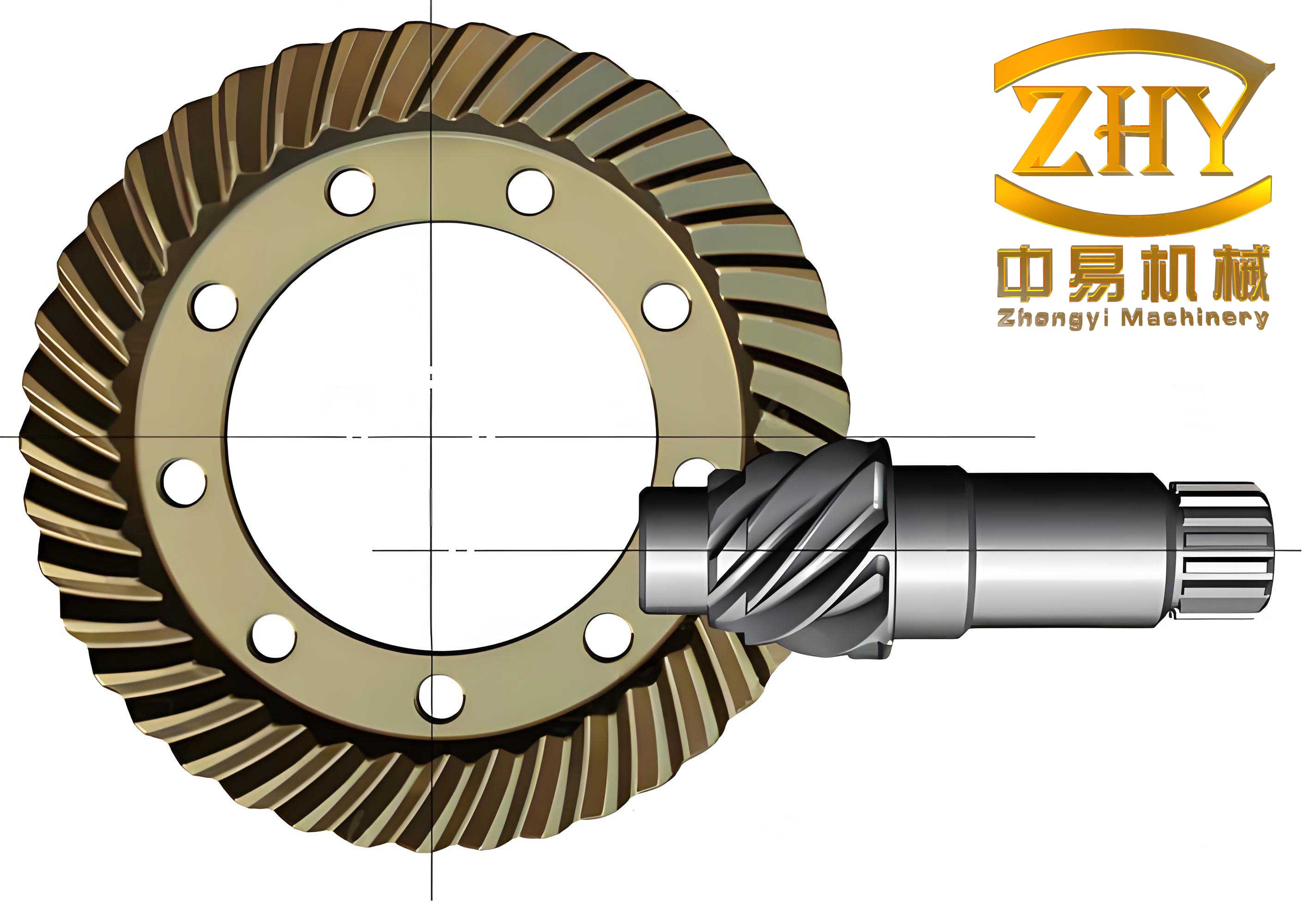
The accurate prediction and control of tooth contact patterns are paramount for the performance, noise, vibration, and harshness (NVH) characteristics, and longevity of automotive drive axle assemblies. Hypoid gears, with their offset axes, offer significant advantages in terms of design flexibility, high torque capacity, and smooth operation. However, their complex geometry and curved tooth flanks make the precise control of the contact area between the pinion and gear a critical and challenging aspect of manufacturing. Traditional methods often rely on iterative physical testing (roll testing) after machining, which is time-consuming and costly. This article presents a robust and efficient methodology for predicting the tooth contact state of hypoid gears, specifically those ground using the HFT (Hypoid Face Topping) process, through a systematic tooth flank mismatch analysis. This simulation-based approach provides a theoretical guide for contact pattern correction prior to or during the gear finishing process.
While Tooth Contact Analysis (TCA) is an indispensable tool in the design phase for evaluating theoretical mesh quality, its application for assessing actual manufactured hypoid gears is less straightforward. Digital TCA techniques using measured point clouds exist but can be complex and sensitive to the accuracy of surface fitting algorithms. The proposed mismatch analysis offers a more direct and intuitive alternative. The core principle involves comparing the actual (or theoretical) pinion tooth surface against a calculated base conjugate pinion flank—a virtual pinion surface that would mate perfectly with the actual (or nominal) gear flank without any mismatch. The deviations between these two surfaces, when mapped topographically, create a tooth flank mismatch topology map that visually predicts the contact pattern’s location, shape, and tendency.
The foundation of this prediction method for HFT-ground hypoid gears lies in three interconnected mathematical models: the HFT grinding model, the conjugate meshing model, and the mismatch calculation algorithm.
Mathematical Model of HFT Grinding Process
The geometry of hypoid gear flanks is fundamentally determined by the manufacturing process. For the HFT grinding method, a cradle-style machine with a tilted cutter head (cutter tilt method) is commonly employed. A unified mathematical model describing the kinematic relationship between the grinding wheel (cutter) and the gear blank is essential. The coordinate systems are established as shown in the schematic, where multiple intermediate frames facilitate the transformation from the cutter body to the workpiece.
Key machine settings for HFT grinding of hypoid gears include:
| Setting Category | Symbol | Description |
|---|---|---|
| Cutter Geometry | $R_c$, $\alpha_c$ | Cutter radius and blade angle. |
| Cutter Orientation | $i$, $j$ | Cutter tilt angle and cutter swivel angle. |
| Machine Kinematics | $S_r$, $q$, $E_m$, $X_b$, $X_p$, $\gamma_m$ | Radial distance, angular position, vertical offset, sliding base distance, axial workpiece offset, and workpiece root angle. |
| Generating Motion | $R_b$ | Machine ratio relating cradle rotation $\phi$ to workpiece rotation $\psi$ ($\psi = R_b \phi$). |
For gear (wheel) grinding using the formate (non-generating) method, the generating motion is disabled ($R_b=0$, $\phi=\psi=0$). The coordinate transformation chain allows the derivation of the position vector $\mathbf{r}_w^{(g)}(u_g, \theta_g)$ and unit normal vector $\mathbf{n}_w^{(g)}(u_g, \theta_g)$ for any point on the gear tooth flank, parameterized by surface coordinates $u_g$ and $\theta_g$, in the workpiece coordinate system $S_w$. Similarly, the pinion flank equations $\mathbf{r}_w^{(p)}(u_p, \theta_p, \phi)$ and $\mathbf{n}_w^{(p)}(u_p, \theta_p, \phi)$ are derived, incorporating the generating motion parameter $\phi$.
Mathematical Model for Conjugate Flank Determination
To perform the mismatch analysis, a reference surface—the pinion base conjugate flank—must be computed. This surface is defined as the theoretical pinion flank that is perfectly conjugate to the actual (or nominal) gear flank under ideal meshing conditions, excluding any intentional mismatch or errors.
The meshing configuration of a hypoid gear pair is defined by the shaft angle $\Sigma$ (typically 90°), offset $E$, and the ratio of teeth $m_{21} = z_2 / z_1$. The coordinate systems for meshing analysis include stationary frames and rotating frames attached to the pinion ($S_1$, rotating by $\varphi_1$) and gear ($S_2$, rotating by $\varphi_2$).
The condition of perfect conjugation is governed by the equation of meshing, which states that the relative velocity vector at the contact point is perpendicular to the common surface normal:
$$
\Phi(u_g, \theta_g, \varphi_2) = \mathbf{n}^{(21)} \cdot \mathbf{v}^{(21)} = 0
$$
where $\mathbf{v}^{(21)}$ is the relative velocity of the gear relative to the pinion at the potential contact point, expressed in a fixed coordinate system. For a constant ratio drive, the rotation angles are linked by $\varphi_1 = m_{21} \varphi_2$. Solving the meshing equation $\Phi=0$ yields the functional relationship $\varphi_2 = \varphi_2(u_g, \theta_g)$.
The procedure to obtain the pinion base conjugate flank is as follows:
- Start with the gear flank $\mathbf{r}_2(u_g, \theta_g)$ and its normal $\mathbf{n}_2(u_g, \theta_g)$ in the gear coordinate system $S_2$.
- Transform these to a fixed reference system $S_d$: $\mathbf{r}_d(u_g, \theta_g, \varphi_2) = \mathbf{M}_{db}\mathbf{M}_{b2}\mathbf{r}_2$, $\mathbf{n}_d(u_g, \theta_g, \varphi_2) = \mathbf{L}_{db}\mathbf{L}_{b2}\mathbf{n}_2$.
- Apply the meshing condition to eliminate $\varphi_2$, obtaining $\mathbf{r}_d(u_g, \theta_g)$ and $\mathbf{n}_d(u_g, \theta_g)$.
- Transform the contact point to the pinion coordinate system $S_1$ using $\varphi_1 = m_{21}\varphi_2(u_g, \theta_g)$: $$\mathbf{r}_1^{(b)}(u_g, \theta_g) = \mathbf{M}_{1d}(\varphi_1) \mathbf{r}_d(u_g, \theta_g)$$ $$\mathbf{n}_1^{(b)}(u_g, \theta_g) = \mathbf{L}_{1d}(\varphi_1) \mathbf{n}_d(u_g, \theta_g)$$
The resulting surface $\mathbf{r}_1^{(b)}$ is the pinion base conjugate flank, which is fully conjugate to the input gear flank.
Construction of the Tooth Flank Mismatch Topology Map
The mismatch analysis is performed by calculating the normal deviations between the actual pinion flank and the pinion base conjugate flank. This process involves discrete point evaluation across the tooth surface.
Let $\mathbf{r}_1^{(p)}(u_p, \theta_p)$ represent the actual (or theoretical) pinion flank points, and $\mathbf{r}_1^{(b)}(u_g, \theta_g)$ represent the corresponding base conjugate flank points. To compare them, they must be referenced to a common grid defined on the pinion tooth. Typically, a grid is defined in terms of profile (height) and lengthwise coordinates. For each grid node $i,j$ on the base conjugate flank with point $\mathbf{r}_{1,ij}^{(b)}$ and unit normal $\mathbf{n}_{1,ij}^{(b)}$, the corresponding point on the actual pinion flank $\mathbf{r}_{1,ij}^{(p)}$ is found.
The essential step is to align the two flanks for comparison. This is typically done by performing a least-squares fitting or aligning specific reference points (e.g., the grid midpoint) to minimize positional misalignment unrelated to surface form deviation. After this alignment, the tooth flank mismatch (deviation) $\Delta \delta_{ij}$ at grid node $(i,j)$ is calculated as the projection of the distance vector onto the base conjugate flank’s normal:
$$
\Delta \delta_{ij} = \left( \mathbf{r}_{1,ij}^{(p)} – \mathbf{r}_{1,ij}^{(b)} \right) \cdot \mathbf{n}_{1,ij}^{(b)}
$$
A positive $\Delta \delta$ indicates the actual pinion material lies “outside” the conjugate surface (potential initial contact point), while a negative value indicates a “gap” or relief.
The graphical representation of $\Delta \delta_{ij}$ across the entire tooth surface forms the tooth flank mismatch topology map. This contour map directly predicts the contact pattern:
- Contact Path: The zone of minimal deviation (around zero) indicates the initial contact line or area.
- Pattern Shape and Bias: The gradient and distribution of deviations show the tendency for contact to be biased towards the toe/heel or top/bottom of the tooth, predicting an “inner diagonal” or “outer diagonal” contact.
- Edge Contact Risk: Severe positive deviations near the tooth edges suggest a high risk of concentrated edge contact under load.
The methodology differs slightly for theoretical vs. measured flanks:
| Analysis Type | Gear Flank Input | Pinion Flank Input | Base Conjugate Flank |
|---|---|---|---|
| Theoretical | Nominal HFT model $\mathbf{r}_2^{nom}$ | Nominal HFT model $\mathbf{r}_1^{nom}$ | Conjugate to $\mathbf{r}_2^{nom}$ |
| Measured / Corrected | Corrected model from measured errors* | Nominal model + measured error map | Conjugate to corrected gear flank |
*Gear flank errors are compensated by inversely adjusting the theoretical machine settings (e.g., $E_m$, $X_p$, $\gamma_m$) to create a corrected mathematical model that closely represents the physical measured gear.
Case Study: Simulation and Experimental Validation
The proposed tooth flank mismatch analysis method is applied to a hypoid gear set from a light passenger vehicle drive axle. The basic design parameters are as follows:
| Parameter | Pinion | Gear (Wheel) |
|---|---|---|
| Number of Teeth ($z$) | 8 | 39 |
| Hand of Spiral | Left | Right |
| Shaft Angle ($\Sigma$) | 90° | |
| Offset ($E$) | 35 mm (Pinion below) | |
| Module at Ref. Point | 6.283 mm | |
| Spiral Angle at Ref. Point ($\beta$) | 50.24° | 31.37° |
| Pressure Angle at Ref. Point ($\alpha$) | 22.5° | |
The HFT grinding machine settings for the gear and pinion are derived from the design. Using the mathematical models, the theoretical tooth flanks are numerically computed, and the pinion base conjugate flank is derived. The theoretical mismatch map for the pinion concave flank (driving side, mating with gear convex flank) is calculated and shown conceptually below.
Interpretation of Theoretical Mismatch Map: The map reveals that the deviations are positive (pinion material high) at the toe-root and heel-top regions, and relatively lower (closer to zero or negative) at the toe-top and heel-root. This pattern predicts an inner diagonal contact (biased towards the pinion toe and gear heel). Furthermore, the magnitude of positive deviation is generally larger at the heel than at the toe, suggesting the initial contact area will be located slightly towards the pinion heel (or gear toe). Crucially, no extreme positive deviations are found at the very edges, indicating no immediate risk of edge contact in the nominal design.
Next, the gears were manufactured on a Gleason 275G 6-axis CNC hypoid grinder. The ground tooth flanks were measured on a gear measuring center (e.g., Klingelnberg P series or similar). The measured flank form errors for both the gear and pinion were obtained.
To analyze the as-manufactured contact prediction, the measured gear errors were used to create a corrected gear flank model by inversely perturbing the nominal machine settings. The pinion base conjugate flank was recalculated from this corrected gear model. The measured pinion errors were then superimposed onto the nominal pinion flank grid to create a simulated “as-measured” pinion flank. The mismatch map between this simulated actual pinion and the new base conjugate flank was generated.
Comparison of Mismatch Maps (Theoretical vs. As-Manufactured):
$$
\text{Change} \approx \Delta \delta_{actual} – \Delta \delta_{theoretical}
$$
The analysis showed a specific trend: the positive deviations at the pinion heel region decreased, while those at the pinion toe region increased slightly. This indicates a reduction in material at the heel and an increase at the toe relative to the perfect conjugate mate. Consequently, the mismatch map predicted that the contact area would shift from the nominal heel-biased position towards the center of the tooth face width, while the basic inner diagonal tendency remained largely unchanged.
Finally, a physical roll test (gear rolling test) was conducted on the manufactured hypoid gear set to obtain the actual contact pattern under light load. The results were compared with the predictions:
- Nominal/Design Contact Pattern: The physical roll test of finally corrected gears showed a contact patch located slightly towards the pinion heel, exhibiting an inner diagonal orientation—closely matching the prediction from the theoretical mismatch map.
- First-Ground (As-Manufactured) Contact Pattern: The roll test pattern from the first grinding trial, before final correction, was indeed observed to be more centralized on the tooth face compared to the design pattern, aligning well with the shift predicted by the as-manufactured mismatch map analysis.
This strong correlation between the mismatch map predictions and the empirical roll test results validates the effectiveness of the proposed tooth flank mismatch analysis method for hypoid gears.
Conclusion
This article has presented a comprehensive methodology for predicting the tooth contact state of HFT-ground hypoid gears through mathematical modeling and tooth flank mismatch analysis. The core of the method involves generating a pinion base conjugate flank from the gear data and comparing it against the actual (or theoretical) pinion flank. The resulting deviation topology map provides a direct and intuitive visual prediction of the contact pattern’s location, shape (diagonal tendency), and risk of edge contact.
The case study demonstrates that the method is not only applicable to theoretical design verification but is particularly powerful for analyzing real manufactured hypoid gears. By incorporating measured flank error data, the predicted shift in contact pattern closely matched the observed change in the physical roll test. This capability allows engineers to move beyond trial-and-error correction. The mismatch map serves as a diagnostic tool, indicating not just that a contact pattern is incorrect, but specifically how the pinion flank deviates from the ideal conjugate form, thereby providing clear, quantitative guidance for corrective adjustments to the pinion grinding machine settings (e.g., modifying machine root angle $\gamma_m$, offset $E_m$, or ratio $R_b$).
In summary, this tooth flank mismatch analysis offers a practical, simulation-driven approach to contact pattern prediction and correction for hypoid gears, enhancing first-pass quality, reducing development time and cost, and contributing to the production of high-performance, low-NHV automotive drive axles. It bridges the gap between theoretical TCA and physical testing, providing a crucial tool for modern precision gear manufacturing.