
In the field of precision transmission, the rotary vector reducer, commonly known as the RV reducer, plays a pivotal role due to its high reduction ratio, compact structure, and exceptional load-bearing capacity. As a key component in robotics, CNC machine tools, and aerospace mechanisms, the performance of the rotary vector reducer directly impacts system accuracy and reliability. Among various performance indicators, torsional stiffness is critical as it determines the reducer’s ability to resist deformation under external loads, thereby influencing positioning precision, dynamic response, and operational stability. In this article, we focus on the core transmission element of the rotary vector reducer—the cycloidal pinwheel mechanism—and propose an analytical method to evaluate torsional stiffness based on elastic torsion angle, considering geometric parameters, profile modifications, and errors. This approach aims to enhance the performance-oriented forward design theory for rotary vector reducers, providing insights for optimizing their load-bearing characteristics.
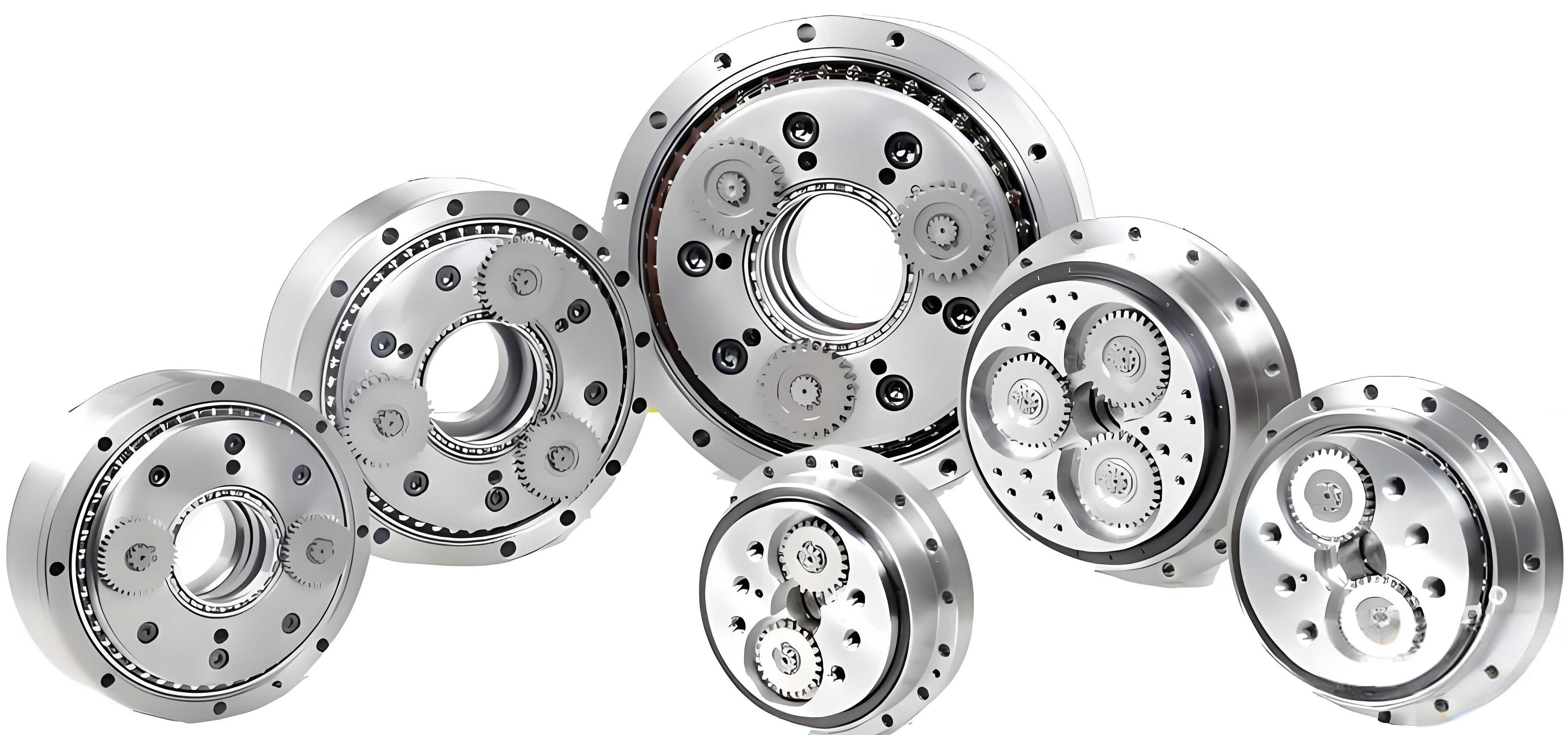
The rotary vector reducer operates as a closed differential gear system, comprising a two-stage transmission: the first stage involves an involute planetary gear set (sun gear and planet gears), and the second stage consists of a cycloidal pinwheel mechanism (crankshafts, cycloidal gears, and pinwheels), with an output mechanism (planet carrier). The unique design of the rotary vector reducer enables high torque transmission and minimal backlash, making it ideal for precision applications. However, under heavy loads, insufficient torsional stiffness can lead to excessive deformation, causing vibrations, increased wear, and reduced lifespan. Therefore, understanding and optimizing the torsional stiffness of the rotary vector reducer is essential for advancing its applications in high-performance systems.
To analyze the torsional stiffness, we begin with a static analysis of the rotary vector reducer. Based on the transmission principle, we establish deformation coordination conditions and static equilibrium equations for the entire system. For the involute gear stage, assuming ideal conditions with no manufacturing or assembly errors, the deformation displacement between the sun gear and planet gears is equal. The deformation coordination condition is given by:
$$ \delta_{sp1} = \delta_{sp2} = \delta_{sp3} $$
where $\delta_{spi}$ represents the deformation displacement between the sun gear and the i-th planet gear. The static equilibrium equation for the sun gear under input torque $T_{in}$ is:
$$ \sum_{i=1}^{3} F_{psi} r_1 = T_{in}, \quad F_{ps1} = F_{ps2} = F_{ps3} $$
Here, $F_{psi}$ is the force exerted by the sun gear on the planet gear, and $r_1$ is the pitch radius of the sun gear. For the planet gears, the equilibrium equations account for forces from the sun gear and crankshafts.
For the cycloidal pinwheel stage, we consider two cycloidal gears mounted 180° out of phase. Under a torque $T_c$, each cycloidal gear engages with multiple pinwheels, resulting in contact deformations. The deformation coordination condition for the cycloidal gear is:
$$ \Delta \delta_k = l_k \beta_c $$
where $\Delta \delta_k$ is the contact deformation at the k-th pinwheel, $l_k$ is the perpendicular distance from the cycloidal gear’s centroid to the contact line, and $\beta_c$ is the微小 rotation angle of the cycloidal gear. The static equilibrium equation for the cycloidal gear is:
$$ \sum F_k l_k = T_c $$
with $F_k$ being the meshing force at the k-th pinwheel. For the bearing elements, such as the转臂 bearings, we assume uniform deformation under forces, leading to similar coordination conditions.
Next, we develop a torsional stiffness analysis model for the rotary vector reducer. The overall torsional stiffness is represented by the elastic torsion angle $\theta_{\Sigma}$, which is the sum of contributions from various components:
$$ \theta_{\Sigma} = \theta_1 + \theta_2 + \theta_3 + \theta_4 + \theta_5 $$
where $\theta_1$ is the torsion angle from the involute gear stage, $\theta_2$ from the cycloidal pinwheel stage, $\theta_3$ from the转臂 bearings, $\theta_4$ from the crankshafts, and $\theta_5$ from the planet carrier. This model allows us to直观 assess how each part affects the overall stiffness of the rotary vector reducer.
For the involute gear stage, the meshing stiffness $k_X$ is derived using elastic mechanics. The equivalent torsional stiffness $K_X$ is:
$$ K_X = k_X r_s^2 $$
where $r_s$ is the base radius. The torsion angle $\theta_1$ on the output shaft is calculated using Hooke’s law:
$$ \theta_1 = \frac{180 \times 3600 F_t}{\pi k_X r_1 i_z} $$
Here, $F_t$ is the tangential force, and $i_z$ is the transmission ratio. This contribution is typically small compared to other stages, highlighting the dominance of the cycloidal pinwheel in the rotary vector reducer’s stiffness.
For the cycloidal pinwheel stage, we account for profile modifications and errors. The initial meshing clearance $\Delta(\phi_k)$ between the cycloidal gear and pinwheel is influenced by equidistance modification $\Delta r_p$, moved distance modification $\Delta R_p$, pinwheel distribution circle radius error $\delta R_p$, and pinwheel radius error $\delta r_p$. The expression is:
$$ \Delta(\phi_k) = \Delta_1(\phi_k) – \Delta_2(\phi_k) $$
$$ \Delta_1(\phi_k) = -\Delta R_p (1 – K_1′ \cos \phi_k – \sqrt{1 – K_1’^2} \sin \phi_k) S^{-1/2} + \Delta r_p (1 – S^{-1/2} \sin \phi_k) $$
$$ \Delta_2(\phi_k) = \delta R_p (1 – K_1′ \cos \phi_k – \sqrt{1 – K_1’^2} \sin \phi_k) S^{-1/2} + \delta r_p (1 – S^{-1/2} \sin \phi_k) $$
where $S = 1 + K_1’^2 – 2K_1′ \cos \phi_k$, $K_1′ = a z_p / (R_p + \Delta R_p)$, $\phi_k$ is the angle of the k-th pinwheel, $a$ is the eccentricity, $z_p$ is the number of pinwheels, and $R_p$ is the pinwheel distribution circle radius. Under load, contact deformation occurs, and using Hertzian contact theory, the deformation $w$ for a cylinder pair is:
$$ w = \frac{2F}{\pi b} \left[ \frac{1 – \mu_1^2}{E_1} \left( \frac{1}{3} + \ln \frac{4R_1}{L} \right) + \frac{1 – \mu_2^2}{E_2} \left( \frac{1}{3} + \ln \frac{4R_2}{L} \right) \right] $$
where $F$ is the force, $b$ is the thickness, $\mu$ and $E$ are Poisson’s ratio and elastic modulus, and $R$ are radii. The maximum deformation $\Delta \delta_{\text{max}}$ is used to determine meshing forces. The meshing force $F_k$ at the k-th pinwheel is:
$$ F_k = F_{\text{max}} \frac{\Delta \delta_k – \Delta(\phi_k)}{\Delta \delta_{\text{max}}} $$
通过 an iterative process based on equilibrium conditions, we solve for $F_{\text{max}}$ and the contact zone. The torsion angle $\theta_2$ due to cycloidal pinwheel deformation is:
$$ \theta_2 = \frac{180 \times 3600 \Delta \theta_b i_b}{\pi} $$
where $\Delta \theta_b$ is the rotation angle of the cycloidal gear, and $i_b$ is the reduction ratio. The equivalent torsional stiffness $K_B$ of the cycloidal pinwheel is the sum of individual tooth pair stiffnesses $K_k$:
$$ K_B = \sum_{k=g}^{G} K_k, \quad K_k = k_b l_k^2 $$
with $k_b$ being the meshing stiffness for a single tooth pair, derived from Hertzian theory considering errors.
For the转臂 bearings, the stiffness $k_s$ is modeled using empirical formulas for roller bearings. The radial force $F_s$ is computed from components of meshing forces, and the torsion angle $\theta_3$ is:
$$ \theta_3 = \frac{180 \times 3600 z_c \Delta \delta_s i_b}{\pi z_p a_0} $$
where $\Delta \delta_s$ is the relative displacement of the bearing rings. For crankshafts, torsion angle $\theta_4$ arises from bending and torsional deformations. Using beam theory and Hooke’s law, we calculate deformations under forces and torques. The torsion angle $\theta_5$ for the planet carrier is derived from its structural stiffness under tangential forces.
To evaluate the impact of design parameters on torsional stiffness, we analyze a standard RV-80E rotary vector reducer with key parameters listed in Table 1.
| Parameter | Symbol | Unit | Value |
|---|---|---|---|
| Sun gear teeth number | $z_1$ | — | 21 |
| Planet gear teeth number | $z_2$ | — | 42 |
| Cycloidal gear teeth number | $z_c$ | — | 39 |
| Pinwheel teeth number | $z_p$ | — | 40 |
| Pinwheel distribution circle radius | $R_p$ | mm | 75 |
| Pinwheel radius | $r_p$ | mm | 3.5 |
| Eccentricity | $a$ | mm | 1.5 |
| Cycloidal gear width | $b$ | mm | 10 |
| Equidistance modification | $\Delta r_p$ | μm | -15 |
| Moved distance modification | $\Delta R_p$ | μm | -30 |
We first examine the influence of geometric parameters on meshing forces in the cycloidal pinwheel. Variations in $R_p$, $a$, and $b$ are studied within practical limits. For instance, as $R_p$ increases from 65 mm to 90 mm, the maximum meshing force decreases, while the number of contact tooth pairs increases from 5 to 8. This is summarized in Table 2.
| $R_p$ (mm) | Max Meshing Force (N) | Number of Contact Pairs |
|---|---|---|
| 65 | High | 5 |
| 71.25 | Moderate | 6 |
| 77.5 | Lower | 8 |
| 83.75 | Low | 8 |
| 90 | Lowest | 8 |
The relationship can be expressed as:
$$ F_{\text{max}} \propto \frac{1}{R_p^\alpha} $$
where $\alpha$ is a positive exponent. For eccentricity $a$, an optimal value exists around 1.5 mm, where meshing force is minimized. For cycloidal gear width $b$, increasing $b$ raises meshing force but does not alter the number of contact pairs beyond a threshold. This highlights the complexity of parameter interactions in the rotary vector reducer.
Profile modifications significantly affect meshing clearances. Under the same radial clearance, different modification combinations yield varying mechanical performance. We compare five cases, as shown in Table 3.
| Combination | Equidistance $\Delta r_p$ (mm) | Moved Distance $\Delta R_p$ (mm) | Normal Clearance $j_{C1}$ (mm) | Meshing Force | Contact Pairs |
|---|---|---|---|---|---|
| Positive equidistance | 0.02 | 0 | 6.84e-4 | Moderate | 7 |
| Negative moved distance | 0 | -0.02 | 4.10e-4 | Higher | 6 |
| Positive equidistance + positive moved distance | 0.03 | 0.01 | 8.21e-4 | Lowest | 8 |
| Positive equidistance + negative moved distance | 0.01 | -0.01 | 5.47e-4 | Moderate | 7 |
| Negative equidistance + negative moved distance | -0.01 | -0.03 | 2.74e-4 | Highest | 7 |
The “positive equidistance + positive moved distance” combination results in the lowest meshing force and most contact pairs, indicating superior load distribution. This is crucial for enhancing the torsional stiffness of the rotary vector reducer. Errors in pinwheel dimensions also play a role. For errors in $R_p$ and $r_p$ ranging from -10 μm to 10 μm, the sensitivity of meshing force is higher for $R_p$ errors, with an average change of 128.7 N compared to 82.5 N for $r_p$ errors. The effect can be modeled as:
$$ \Delta F_{\text{max}} = \beta \delta R_p + \gamma \delta r_p $$
where $\beta$ and $\gamma$ are coefficients with $\beta > \gamma$.
Moving to stiffness analysis, we evaluate meshing stiffness $k_b$ and torsional stiffness $K_B$ for the cycloidal pinwheel under identical contact zones. The meshing stiffness for a single tooth pair is given by:
$$ k_b = \frac{\pi b E R_p’ S^{3/2}}{4(1 – \mu^2)(R_p’ S^{3/2} + 2 T’ r_p’)} $$
where $R_p’ = R_p + \delta R_p$, $r_p’ = r_p + \delta r_p$, and $T’$ is a geometric term. The equivalent torsional stiffness $K_k$ is $k_b l_k^2$. Summing over contact pairs yields $K_B$. Variations in $R_p$, $a$, and $b$ influence $K_B$ as shown in Table 4.
| Parameter | Trend vs. $K_B$ | Magnitude Change |
|---|---|---|
| Pinwheel distribution circle radius $R_p$ | Negative correlation | Decrease by ~2% per mm increase |
| Eccentricity $a$ | Positive correlation | Increase by ~5% per 0.1 mm increase |
| Cycloidal gear width $b$ | Positive correlation | Increase by ~8% per mm increase |
These trends emphasize that increasing eccentricity and gear width boosts stiffness, while larger distribution circle radii reduce it. However, in the context of the entire rotary vector reducer, the overall torsional angle $\theta_{\Sigma}$ is the key metric. We compute $\theta_{\Sigma}$ for different parameter sets, with results in Table 5.
| Component | Torsion Angle $\theta$ (arc-seconds) |
|---|---|
| Involute gear stage | 0.2286 |
| Cycloidal pinwheel stage | 19.5609 |
| Crankshafts | 10.6505 |
| 转臂 bearings | 51.4250 |
| Planet carrier | 22.3682 |
| Total $\theta_{\Sigma}$ | 104.2332 |
The转臂 bearings contribute the most to the torsion angle, indicating their critical role in stiffness. For design parameters, we analyze their impact on $\theta_{\Sigma}$. As $R_p$ increases from 70 mm to 80 mm, $\theta_{\Sigma}$ decreases gradually, showing a negative correlation. The relationship can be approximated as:
$$ \theta_{\Sigma} \approx \theta_0 – \lambda R_p $$
where $\theta_0$ and $\lambda$ are constants. For eccentricity $a$, increasing from 1.2 mm to 1.8 mm reduces $\theta_{\Sigma}$ significantly, with the effect saturating above 1.6 mm. For cycloidal gear width $b$, increasing from 10 mm to 15 mm reduces $\theta_{\Sigma}$ more noticeably than $R_p$. This underscores the importance of selecting appropriate geometric dimensions to optimize the rotary vector reducer’s stiffness.
Profile modifications also affect $\theta_{\Sigma}$. As equidistance modification $\Delta r_p$ increases from 0 to 20 μm, $\theta_{\Sigma}$ increases by 7.48 arc-seconds. For moved distance modification $\Delta R_p$ from -20 μm to 0, $\theta_{\Sigma}$ decreases by 9.61 arc-seconds. Thus, moved distance modification has a greater impact, suggesting that tighter control over this parameter is essential for stiffness optimization in rotary vector reducers. Errors in pinwheel dimensions show similar trends: $\theta_{\Sigma}$ increases with both $\delta R_p$ and $\delta r_p$, but $\delta R_p$ has a more pronounced effect, reinforcing the need for precision in manufacturing the pinwheel distribution circle.
In conclusion, our analysis provides a comprehensive framework for evaluating torsional stiffness in rotary vector reducers based on elastic torsion angle. We have shown that the cycloidal pinwheel mechanism is central to stiffness performance, with design parameters such as pinwheel distribution circle radius, eccentricity, and gear width playing crucial roles. Profile modifications and errors further influence meshing forces and stiffness, with moved distance modification and pinwheel distribution circle radius errors being particularly sensitive. These insights can guide the design and optimization of rotary vector reducers for enhanced load-bearing capacity and precision. Future work could involve dynamic stiffness analysis or experimental validation to refine the models. Overall, understanding these relationships is key to advancing the performance of rotary vector reducers in high-demand applications.
To further illustrate, we derive key formulas used in the analysis. The deformation coordination for the cycloidal gear is expressed as:
$$ \Delta \delta_k = l_k \beta_c = l_k \frac{\Delta \delta_{\text{max}}}{r_c’} $$
The static equilibrium for the cycloidal gear under torque $T_c$ is:
$$ T_c = \sum_{k=g}^{G} F_k l_k $$
Using Hertzian contact theory, the contact deformation $w$ for cylindrical bodies is generalized as:
$$ w = \frac{2F}{\pi b} \left( \frac{1 – \mu_1^2}{E_1} C_1 + \frac{1 – \mu_2^2}{E_2} C_2 \right) $$
where $C_1$ and $C_2$ are logarithmic terms dependent on radii. For the rotary vector reducer overall, the torsional angle model integrates contributions from all stages, enabling a holistic assessment. This approach not only aids in design but also in troubleshooting stiffness issues in practical applications of rotary vector reducers.
In summary, the rotary vector reducer’s torsional stiffness is a multifaceted property influenced by geometric design, modifications, and errors. By leveraging analytical models and parametric studies, we can optimize these factors to achieve superior performance. This work contributes to the ongoing development of high-precision transmission systems, ensuring that rotary vector reducers meet the stringent demands of modern engineering.