
In the realm of precision mechanical transmissions, the rotary vector reducer stands as a critical component, widely employed in robotics, aerospace, and industrial automation due to its high torque density, compact structure, and excellent positioning accuracy. The cycloid gear, a core element within the rotary vector reducer, directly influences the overall performance and service life of the system. Specifically, the bearing holes on the cycloid gear require exceptionally high dimensional accuracy and surface finish, as their quality dictates the assembly precision and operational smoothness of the rotary vector reducer. Precision boring is the final and most crucial step in machining these bearing holes, where cutting parameters such as feed rate profoundly affect cutting temperature, tool forces, and consequently, the final part quality. This study focuses on the precision boring process of the bearing hole for an RV80E rotary vector reducer’s cycloid gear, utilizing finite element simulation to analyze the effects of feed rate and establish optimal machining parameters.
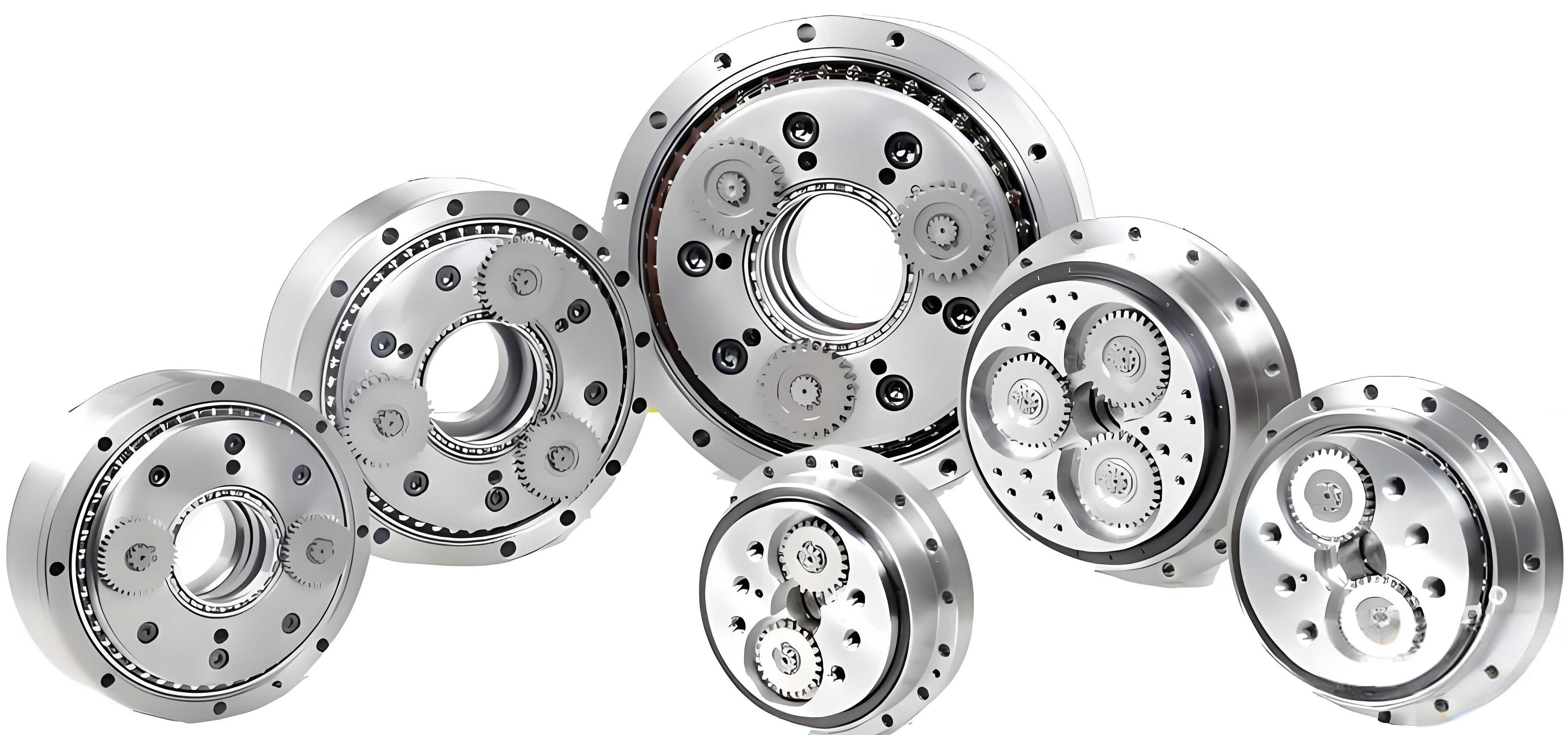
The design and manufacturing of components for a rotary vector reducer demand meticulous attention to detail. The cycloid gear, typically made from hardened bearing steel like GCr15, undergoes heat treatment to achieve high hardness and wear resistance. The bearing holes, with tight tolerances (e.g., H7) and low surface roughness (Ra 0.8 μm), necessitate a stable and controlled finishing operation. Boring, as an internal turning process, is susceptible to challenges like tool deflection and thermal deformation, which can compromise accuracy. Therefore, understanding the interplay between cutting parameters and process outcomes through simulation is vital for optimizing the manufacturing of rotary vector reducer parts.
This investigation employs the metal cutting finite element software AdvantEdge FEM to simulate the precision boring process. The primary objective is to model the evolution of cutting temperature and cutting forces under varying feed rates while maintaining a constant cutting speed. By analyzing these simulated results, we aim to identify the feed rate range that minimizes adverse thermal and mechanical effects, thereby ensuring the machining precision required for the reliable operation of the rotary vector reducer. The following sections detail the simulation methodology, present and discuss the results, and provide practical recommendations.
1. Methodology: Finite Element Simulation Setup
To accurately replicate the precision boring operation for the cycloid gear bearing hole, a detailed finite element model was constructed within AdvantEdge FEM. The process mirrors the finishing cut where material removal is minimal but quality requirements are stringent. All simulations were conducted from a first-person perspective as the analyst configuring and interpreting the model.
1.1 Workpiece and Tool Geometry
The workpiece represents a segment of the RV80E cycloid gear focusing on one of its three identical bearing holes. The hole has an inner diameter of 36 mm, and the gear thickness is 12 mm. The tool is a single-point boring tool with a Cubic Boron Nitride (CBN) insert, chosen for its exceptional hardness and thermal stability, suitable for finishing hardened steels in rotary vector reducer components. The tool geometry significantly influences chip formation, forces, and temperature. The standard tool angles were defined as: rake angle $\gamma_0 = -5^\circ$, clearance angle $\alpha_0 = 10^\circ$, cutting edge inclination angle $\lambda_s = 5^\circ$, and approach angle $\kappa_r = 90^\circ$.
Since AdvantEdge FEM uses a different coordinate system defining angles as Back Rake (BR) and Side Rake (SR), conversion was necessary. The transformation equations are:
$$ \tan(BR) = \tan(\gamma_0) \cdot \sin(\kappa_r) + \tan(\lambda_s) \cdot \cos(\kappa_r) $$
$$ \tan(SR) = \tan(\gamma_0) \cdot \cos(\kappa_r) – \tan(\lambda_s) \cdot \sin(\kappa_r) $$
Substituting the values: $\gamma_0 = -5^\circ$, $\kappa_r = 90^\circ$, $\lambda_s = 5^\circ$ yields:
$$ \tan(BR) = \tan(-5^\circ) \cdot \sin(90^\circ) + \tan(5^\circ) \cdot \cos(90^\circ) = \tan(-5^\circ) \cdot 1 + \tan(5^\circ) \cdot 0 \approx -0.0875 $$
$$ BR \approx -5^\circ $$
$$ \tan(SR) = \tan(-5^\circ) \cdot \cos(90^\circ) – \tan(5^\circ) \cdot \sin(90^\circ) = \tan(-5^\circ) \cdot 0 – \tan(5^\circ) \cdot 1 \approx -0.0875 $$
$$ SR \approx -5^\circ $$
The lead angle in the software was set equal to the approach angle’s complement effect, defined as Lead Angle = $-5^\circ$ for this configuration. This precise geometric definition ensures an accurate representation of the tool-workpiece interaction during the boring of the rotary vector reducer part.
1.2 Material Properties
The workpiece material is GCr15 bearing steel (equivalent to AISI 52100), a common choice for rotary vector reducer cycloid gears due to its high carbon content and excellent wear resistance after heat treatment. The tool material is CBN. Their essential thermo-mechanical properties are summarized in Table 1. These properties are critical inputs for the finite element model, governing elastic deformation, plastic flow, heat generation, and conduction.
| Material | Elastic Modulus (GPa) | Poisson’s Ratio | Density (kg/m³) | Thermal Expansion Coefficient (10⁻⁶/°C) | Thermal Conductivity (W/(m·K)) |
|---|---|---|---|---|---|
| GCr15 (Workpiece) | 207 | 0.30 | 7850 | 11.1 | 44.8 |
| CBN (Tool) | 720 | 0.15 | 3480 | 2.2 | 79.5 |
The constitutive behavior of GCr15 during machining is modeled using a power-law material model that accounts for strain hardening, strain-rate sensitivity, and thermal softening. The flow stress $\sigma$ is expressed as:
$$ \sigma = \sigma_0 \cdot (1 + \frac{\epsilon}{\epsilon_0})^n \cdot (\frac{\dot{\epsilon}}{\dot{\epsilon}_0})^m \cdot (1 – \alpha_T (T – T_0)^\beta) $$
where $\sigma_0$ is the initial yield stress, $\epsilon$ is the plastic strain, $\epsilon_0$ is the reference strain, $n$ is the hardening exponent, $\dot{\epsilon}$ is the strain rate, $\dot{\epsilon}_0$ is the reference strain rate, $m$ is the strain-rate sensitivity exponent, $\alpha_T$ is the thermal softening coefficient, $T$ is the temperature, $T_0$ is the room temperature, and $\beta$ is the thermal softening exponent. These parameters are integral to the software’s material library for simulating the machining of rotary vector reducer components.
1.3 Mesh Generation and Simulation Parameters
An adaptive meshing technique with four-node tetrahedral elements was employed. The mesh is refined in the primary shear zone and tool-chip contact region to capture high gradients of strain, strain rate, and temperature. The workpiece mesh had a maximum element size of 0.6 mm and a minimum of 0.05 mm. The tool mesh was finer with a maximum size of 0.3 mm and a minimum of 0.03 mm to accurately resolve tool stresses and temperatures. The initial temperature for both workpiece and tool was set to 20°C.
The cutting speed was fixed at 150 m/min, a value selected based on practical machining guidelines for finishing hardened steels with CBN tools in rotary vector reducer manufacturing. The spindle speed corresponding to a 36 mm diameter bore is approximately:
$$ N = \frac{v_c \cdot 1000}{\pi \cdot D} = \frac{150 \cdot 1000}{\pi \cdot 36} \approx 1326 \, \text{rpm} $$
For simulation consistency, a spindle speed of 1600 rpm was used, which closely matches the required cutting speed. The depth of cut for this finishing operation was implicitly set by the model geometry as the tool engages the bore wall. The key variable investigated was the feed per revolution ($f$). Four feed rates were simulated: 0.01 mm/rev, 0.03 mm/rev, 0.05 mm/rev, and 0.08 mm/rev. Each simulation modeled a full 360° rotation of the tool to capture the steady-state cutting conditions. Other simulation parameters are listed in Table 2.
| Parameter | Value |
|---|---|
| Simulation Mode | Standard (Transient) |
| Cutting Speed ($v_c$) | 150 m/min |
| Spindle Speed ($N$) | 1600 rpm |
| Feed per Revolution ($f$) | 0.01, 0.03, 0.05, 0.08 mm/rev |
| Rotation Angle | 360° |
| Initial Temperature | 20 °C |
| Tool Edge Radius | 0.02 mm (implicit in sharp model) |
| Friction Model | Coulomb friction with shear factor |
2. Results: Simulation of Cutting Temperature and Forces
The AdvantEdge FEM software outputs detailed temporal and spatial data for variables like temperature, forces, and stresses. Post-processing this data allows for a comprehensive analysis of the boring process’s impact on the rotary vector reducer cycloid gear.
2.1 Evolution of Cutting Temperature
For a representative case with $f = 0.05$ mm/rev, the temperature distribution on the tool is shown in Figure 3 (described textually). The maximum temperature is localized at the tool-chip interface on the rake face, a region experiencing severe friction and plastic deformation. As cutting progresses, the temperature rapidly rises from ambient to a steady-state value. The heat generated is partitioned among the chip, workpiece, and tool. For the rotary vector reducer’s hardened steel, a significant portion is carried away by the chip, but the heat conducted into the tool and workpiece can still cause thermal expansion and potential microstructural alterations.
The instantaneous maximum tool temperature for each feed rate was extracted from the simulation. The relationship between feed rate and maximum cutting temperature is plotted in Figure 4 and quantified in Table 3. The temperature increase can be attributed to the greater volume of material removed per unit time at higher feeds, leading to increased plastic work and frictional energy conversion to heat. A power-law relationship often describes this trend:
$$ T_{max} \propto f^{\,k_T} $$
where $k_T$ is a positive exponent dependent on material and cutting conditions.
| Feed Rate, $f$ (mm/rev) | Max. Tool Temperature (°C) | Max. Cutting Force, $F_c$ (N) | Max. Thrust Force, $F_t$ (N) | Max. Feed Force, $F_f$ (N) |
|---|---|---|---|---|
| 0.01 | 285 | 68.2 | 45.1 | 12.5 |
| 0.03 | 332 | 89.7 | 62.8 | 24.8 |
| 0.05 | 398 | 121.5 | 85.3 | 41.5 |
| 0.08 | 492 | 178.4 | 124.9 | 66.8 |
The forces $F_c$, $F_t$, and $F_f$ correspond to the tangential (cutting speed direction), radial (depth of cut direction), and axial (feed direction) components, respectively, in a boring operation. For the rotary vector reducer’s bore machining, the radial force ($F_t$) is particularly critical as it can cause tool deflection and bore form errors.
2.2 Evolution of Cutting Forces
The time-history of the three force components for $f = 0.05$ mm/rev is shown in Figure 5. During initial engagement, forces spike transiently before stabilizing. The tangential force $F_c$ is generally the largest, associated with the main power consumption. The feed force $F_f$ remains relatively constant, while the radial force $F_t$ shows some fluctuation due to the continuous entry and exit of the tool edge in the curved bore surface. The steady-state values are of primary interest for process stability assessment in rotary vector reducer manufacturing.
The maximum values of each force component across the different feed rates are summarized in Table 3. All force components exhibit a monotonic increase with feed rate. This relationship is often modeled by the classic cutting force equation:
$$ F_c = k_c \cdot a_p \cdot f $$
$$ F_t = k_t \cdot a_p \cdot f $$
$$ F_f = k_f \cdot a_p \cdot f $$
where $k_c$, $k_t$, and $k_f$ are specific cutting pressures (N/mm²), and $a_p$ is the depth of cut. In precision boring, $a_p$ is often small and constant. The data suggests the specific pressures may themselves have a weak dependence on feed due to size effects and changing shear angles. The increase in forces directly impacts the stress on the boring bar, potentially leading to chatter, dimensional inaccuracy, and poor surface finish on the rotary vector reducer component.
3. Discussion: Optimization of Feed Rate for Rotary Vector Reducer Manufacturing
The simulation results provide clear insights into the trade-offs involved in selecting the feed rate for the precision boring of cycloid gear bearing holes in a rotary vector reducer. The primary goal is to achieve the required surface integrity and dimensional accuracy while maintaining reasonable productivity.
3.1 Influence of Feed Rate on Process Outcomes
The data from Table 3 is analyzed to understand the sensitivity of temperature and forces to feed rate. The percentage increase from the lowest to highest feed is calculated for key outputs:
- Maximum Temperature: Increase of approximately 73% (from 285°C to 492°C).
- Maximum Cutting Force $F_c$: Increase of approximately 162% (from 68.2 N to 178.4 N).
- Maximum Thrust Force $F_t$: Increase of approximately 177% (from 45.1 N to 124.9 N).
This indicates that forces are more sensitive to feed rate changes than temperature in this range for the rotary vector reducer material. The thrust force ($F_t$) growth is particularly concerning as it acts perpendicular to the bore wall, directly contributing to tool deflection. Deflection $\delta$ of a cantilever boring bar can be estimated by:
$$ \delta \propto \frac{F_t \cdot L^3}{E \cdot I} $$
where $L$ is the overhang, $E$ is Young’s modulus, and $I$ is the moment of inertia. Even a small increase in $F_t$ can lead to a proportional increase in deflection, causing bore taper or roundness error, which is unacceptable for high-precision rotary vector reducer assemblies.
Thermally, temperatures exceeding 400-450°C for hardened steel can sometimes lead to tempering effects or accelerated tool wear, especially if the CBN tool has a metallic binder. The simulated temperatures up to 492°C at $f=0.08$ mm/rev suggest a risk of compromising the subsurface integrity of the rotary vector reducer cycloid gear.
3.2 Determination of Optimal Feed Rate Range
To select an optimal feed rate, multiple criteria must be balanced: minimizing cutting forces (to reduce deflection and vibration), controlling temperature (to protect workpiece and tool), and maximizing material removal rate (for productivity). The material removal rate (MRR) for boring is given by:
$$ \text{MRR} = \pi \cdot D \cdot a_p \cdot f \cdot N $$
For a constant $D$, $a_p$, and $N$, MRR is linear with $f$. However, the negative effects of force and temperature rise non-linearly.
Analyzing the data trends (Figures 4 & 6 described textually, data in Table 3), two regimes are apparent:
- Low-Feed Regime ($f = 0.01$ to $0.03$ mm/rev): Forces and temperature increase gradually. The process is very stable but MRR is low.
- Moderate-Feed Regime ($f = 0.03$ to $0.05$ mm/rev): The increases in temperature and force remain manageable while MRR improves significantly.
- High-Feed Regime ($f > 0.05$ mm/rev): Beyond $f = 0.05$ mm/rev, both temperature and forces, especially $F_t$, show a steeper ascent. The incremental gain in MRR comes at a disproportionately high cost in potential accuracy loss.
Therefore, the optimal feed rate range for precision boring the bearing hole of this rotary vector reducer cycloid gear, with a cutting speed of 150 m/min, is identified as $0.03$ to $0.05$ mm/rev. Within this window:
- Maximum tool temperature is contained between 330°C and 400°C, reducing risks of thermal damage.
- Cutting and thrust forces are at levels that a properly sized boring bar can withstand with minimal deflection.
- A satisfactory material removal rate is achieved for a finishing operation.
This recommendation aligns with general machining practice for hard finishing and is now substantiated by quantitative finite element analysis specific to the rotary vector reducer component.
3.3 Implications for Rotary Vector Reducer Performance
The bearing hole’s quality directly affects the fit and preload of the bearing within the rotary vector reducer. An out-of-round or tapered bore caused by excessive tool forces can lead to uneven bearing load distribution, increased friction, heat generation, and premature failure of the reducer. Similarly, high machining temperatures that alter the surface layer hardness can reduce the contact fatigue life of the cycloid gear. By optimizing the feed rate as proposed, manufacturers can enhance the consistency and reliability of rotary vector reducer production. Furthermore, the simulation methodology established here can be extended to other critical machining operations for rotary vector reducers, such as gear tooth grinding or housing boring, creating a digital twin approach for process optimization.
4. Conclusion
This study conducted a detailed finite element simulation of the precision boring process for the bearing hole of an RV80E rotary vector reducer’s cycloid gear. Using AdvantEdge FEM software, the effects of feed rate on cutting temperature and three-axis cutting forces were systematically investigated while maintaining a constant cutting speed of 150 m/min. The simulations revealed that both temperature and forces increase with feed rate, with cutting forces exhibiting greater sensitivity. The radial (thrust) force, critical for bore geometric accuracy, rises significantly at higher feeds.
Based on the analysis of simulated data, an optimal feed rate range of $0.03$ to $0.05$ mm per revolution is recommended for this specific application in rotary vector reducer manufacturing. This range balances the competing objectives of process stability, surface integrity, and productivity. Employing feed rates within this window should minimize tool deflection and thermal damage, thereby ensuring the high dimensional accuracy and surface finish required for the reliable performance of the rotary vector reducer. The findings demonstrate the value of metal cutting simulation as a powerful tool for optimizing machining parameters for critical components like those found in advanced rotary vector reducers, reducing the need for costly trial-and-error in physical machining.
5. Future Work
To build upon this research, several avenues are proposed. First, the simulation model could be validated through physical experiments measuring forces, temperature, and bore geometry on an actual rotary vector reducer cycloid gear. Second, the study could be expanded to include the effects of other parameters such as cutting speed, depth of cut, and tool nose radius. Third, investigating the impact of different coolant strategies or tool coatings (e.g., PVD-coated CBN) on the process outcomes would be valuable for further optimization of rotary vector reducer manufacturing. Finally, integrating this machining process model into a holistic digital thread for the design and production of rotary vector reducers could significantly advance the field of precision gear manufacturing.