
In the field of precision machinery, the rotary vector reducer stands out as a critical component due to its compact design, high torque density, and exceptional positioning accuracy. This device is extensively employed in industrial robots, machine tools, and satellite systems, where reliable performance under load is paramount. The core of the rotary vector reducer’s second-stage reduction mechanism is the cycloidal pin wheel pair, comprising a cycloidal gear and a pin wheel. The contact behavior between these elements directly influences the reducer’s lifespan, efficiency, and vibrational characteristics. Therefore, understanding the transient contact state during initial meshing under load is essential for optimizing design and ensuring operational reliability. In this study, we employ finite element analysis to investigate the contact stress distribution and deformation patterns of the cycloidal pin wheel pair at the moment of initial engagement, considering tooth profile modifications and realistic working conditions.
The rotary vector reducer typically integrates a first-stage planetary gear system with a second-stage cycloidal drive. The cycloidal pin wheel pair consists of a cycloidal gear with lobed teeth and a pin wheel equipped with cylindrical pins. During operation, the eccentric motion of the cycloidal gear relative to the fixed pin wheel generates a reduction in speed and an increase in torque. The contact between the cycloidal tooth profiles and the pins is multi-tooth and intermittent, leading to complex stress fields. To accurately capture this phenomenon, we developed a detailed three-dimensional model using parametric design principles, ensuring high fidelity in tooth geometry, especially after profile modification.
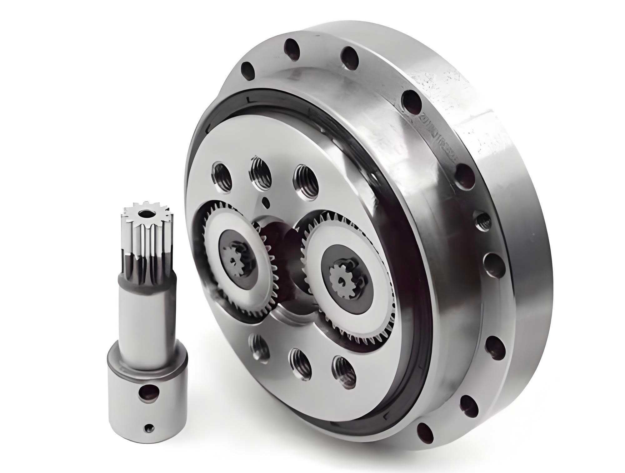
Our modeling approach leverages the ANSYS Parametric Design Language (APDL) to generate the cycloidal gear and pin wheel geometries directly within the finite element environment, avoiding import errors. The tooth profile of the cycloidal gear is derived from the standard cycloidal curve equation, modified to account for manufacturing adjustments. The parametric equations for the tooth profile, without modification, are given by:
$$ x(\theta) = (R_p – r) \cos(\theta) – e \cos(Z_p \theta) $$
$$ y(\theta) = (R_p – r) \sin(\theta) + e \sin(Z_p \theta) $$
where $R_p$ is the pitch radius of the pin wheel, $r$ is the pin radius, $e$ is the eccentricity, $Z_p$ is the number of pins, and $\theta$ is the angular parameter ranging from $0$ to $2\pi$. For the modified profile, we incorporate radial modification amounts $\Delta r$ and $\Delta R_p$, which alter the effective pin radius and pitch radius, respectively, to optimize load distribution and reduce backlash. The modified equations become:
$$ x_{\text{mod}}(\theta) = ((R_p + \Delta R_p) – (r + \Delta r)) \cos(\theta) – e \cos(Z_p \theta) $$
$$ y_{\text{mod}}(\theta) = ((R_p + \Delta R_p) – (r + \Delta r)) \sin(\theta) + e \sin(Z_p \theta) $$
These equations ensure that the tooth profile is accurately represented in the finite element model. The three-dimensional geometry is then extruded to the actual width of the cycloidal gear, and pin holes are added based on the planetary carrier configuration. For computational efficiency, we simplify the system to a single cycloidal gear interacting with a set of pins, assuming the pin length equals the gear width. This simplification is valid for studying contact mechanics without loss of generality.
To discretize the model, we select SOLID185 hexahedral elements due to their superior accuracy and resistance to distortion compared to tetrahedral elements. The meshing strategy involves local refinement at the tooth contact regions to capture high stress gradients, while coarser elements are used elsewhere to maintain computational efficiency. The mesh size on the tooth profile is set to 0.25 mm, and the global element size is 1 mm. The VSWEEP command in ANSYS is utilized to generate a structured hexahedral mesh, ensuring high-quality elements throughout the model. The finite element model comprises approximately 500,000 nodes and 400,000 elements, balancing detail and solution time.
Contact pairs are defined between the cycloidal gear teeth and the pins to simulate the interaction under load. Given that both components are made of steel, we treat the contact as flexible surface-to-surface. The gear tooth surfaces are designated as target surfaces using TARGE170 elements, while the pin surfaces are contact surfaces using CONTA174 elements. Friction is considered with a coefficient of 0.3, and the augmented Lagrange algorithm is employed for robust contact resolution. To model the initial meshing state, we assume that the first 13 teeth are potentially in contact, and contact pairs are created for these teeth. Key contact settings include no automatic adjustment for initial gaps (K5=0), elimination of initial penetration (K9=1), and unilateral contact in the normal direction (K12=0). This setup mimics the actual engagement where multiple teeth may share the load due to elastic deformation.
The boundary conditions and loads are applied to reflect the operational scenario of the rotary vector reducer. In our configuration, the pin wheel is fixed, and the planetary carrier outputs the motion. The pins are constrained in all translational degrees of freedom and rotations about the X and Y axes. To simulate the cycloidal gear’s combined rotation and revolution, we create multipoint constraint (MPC) elements at the centers of the crank shaft holes and the pin wheel center. A MASS21 element is placed at the gear’s center hole to represent the eccentric mass. Constraints are applied via coupling equations to enforce rigid-body motion between the crank shaft holes and the pin wheel center, representing the planetary carrier output. The gear’s center hole is constrained in translation and rotation about X and Y axes to allow only eccentric motion. A torque load of 167 N·m is applied at the planetary carrier, corresponding to the rated load of the rotary vector reducer.
The material properties for both the cycloidal gear and pins are defined as linear elastic, with Young’s modulus of 206 GPa and Poisson’s ratio of 0.3, typical for high-strength steel. The geometric parameters, material properties, and modification amounts are summarized in the tables below to provide a comprehensive overview of the model setup.
| Parameter | Symbol | Value |
|---|---|---|
| Number of cycloidal gear teeth | $Z_c$ | 39 |
| Number of pins | $Z_p$ | 40 |
| Pin wheel pitch radius | $R_p$ | 52.5 mm |
| Pin radius | $r$ | 2.35 mm |
| Eccentricity | $e$ | 0.9 mm |
| Cycloidal gear pitch radius | $r_c$ | 35.1 mm |
| Pin wheel pitch radius (theoretical) | $r_p$ | 36 mm |
| Bearing hole position radius | $l$ | 24 mm |
| Cycloidal gear width | $b$ | 8.9 mm |
| Output speed | $n$ | 15 rpm |
| Component | Young’s Modulus (Pa) | Poisson’s Ratio |
|---|---|---|
| Cycloidal Gear | $2.06 \times 10^{11}$ | 0.3 |
| Pin | $2.06 \times 10^{11}$ | 0.3 |
| Profile Type | Radial Modification $\Delta r$ (μm) | Pitch Radius Modification $\Delta R_p$ (μm) |
|---|---|---|
| Standard Cycloidal Tooth | 0 | 0 |
| Modified Cycloidal Tooth | 5.69 | -3.68 |
Upon solving the finite element model under static load conditions, we analyze the contact stress distribution and deformation patterns. The results indicate that, at the initial meshing instant, six teeth simultaneously participate in load transmission, contrary to the single-tooth contact expected under no-load conditions for a modified profile. This multi-tooth engagement is attributed to elastic deformation of the cycloidal gear under torque, which compensates for the initial gaps between teeth and pins. The von Mises stress contour reveals that the highest stresses occur near the contact regions, with the maximum contact pressure observed on the sixth tooth from the reference point. This suggests that the sixth tooth is the first to engage under load, highlighting the effect of profile modification on the load-sharing sequence.
The contact stress on each engaged tooth pair is extracted and plotted to quantify the load distribution. The maximum contact pressure $p_{\text{max}}$ for each tooth can be approximated using the Hertzian contact theory for cylindrical surfaces, though the finite element analysis provides more accurate results due to complex geometry. The Hertzian formula for two cylinders in contact is:
$$ p_{\text{max}} = \sqrt{\frac{F E^*}{\pi R^* L}} $$
where $F$ is the normal load per unit length, $E^*$ is the equivalent Young’s modulus given by $\frac{1}{E^*} = \frac{1-\nu_1^2}{E_1} + \frac{1-\nu_2^2}{E_2}$, $R^*$ is the equivalent radius $\frac{1}{R^*} = \frac{1}{R_1} \pm \frac{1}{R_2}$ (sign depends on curvature), and $L$ is the contact length. However, in our finite element model, the actual contact pressure is derived directly from the solution. The results show that the contact pressure on the sixth tooth reaches approximately 1.2 GPa, while the other engaged teeth exhibit pressures ranging from 0.4 to 0.9 GPa, indicating non-uniform load sharing.
Deformation analysis reveals significant elastic distortion in the cycloidal gear, particularly near the engaged teeth and pin holes. The nodal displacement vector plot shows that displacements increase radially outward from the gear center, as expected from the eccentric motion. However, in the contact zones, the displacement is constrained by the reaction forces from the pins, leading to localized inward deformation of the tooth profiles. Additionally, the pin holes adjacent to the engaged teeth undergo ovalization due to high compressive stresses, with the major axis of the ellipse aligning with the load direction. This deformation underscores the importance of structural integrity in these regions for the durability of the rotary vector reducer. The crank shaft holes, being reinforced by virtual rigid regions in the model, show negligible deformation, consistent with the presence of support from bearings in actual assemblies.
To further elucidate the stress state, we compute the equivalent strain energy density $U$ in the contact regions, which is indicative of potential fatigue initiation sites. The strain energy density is given by:
$$ U = \frac{1}{2} \sigma_{ij} \epsilon_{ij} $$
where $\sigma_{ij}$ and $\epsilon_{ij}$ are the stress and strain tensors, respectively. High values of $U$ are observed at the root of the cycloidal teeth and around the pin holes, suggesting that these areas are critical for design optimization. The overall deformation of the gear results in a slight torsional twist, quantified by the angular displacement of the planetary carrier relative to the input. This twist, measured as approximately 0.0015 radians under full load, contributes to the positional error of the rotary vector reducer and must be minimized through stiffness enhancements.
In conclusion, our finite element contact analysis of the cycloidal pin wheel pair in a rotary vector reducer provides valuable insights into the transient meshing behavior under load. The study demonstrates that profile modification leads to multi-tooth engagement at initial contact, with the sixth tooth bearing the highest stress. Deformation patterns highlight vulnerable zones such as tooth roots and pin holes, where stress concentrations may lead to failure over time. These findings can guide the design of more robust rotary vector reducers by optimizing tooth profiles, material selection, and structural geometry. Future work may extend this analysis to dynamic conditions, thermal effects, and lubrication influences to further enhance the performance and reliability of rotary vector reducers in high-precision applications.
The rotary vector reducer’s efficiency hinges on the precise interaction between the cycloidal gear and pin wheel, and our analysis underscores the complexity of this contact phenomenon. By leveraging advanced finite element techniques, we can predict and mitigate potential issues, ensuring that rotary vector reducers meet the demanding requirements of modern industrial systems. The integration of parametric modeling, detailed meshing, and realistic boundary conditions has enabled a comprehensive evaluation, paving the way for iterative design improvements in rotary vector reducer technology.