
In the evolving landscape of mechanical design, the transition from traditional, static Computer-Aided Design (CAD) models to dynamic, intelligent ones marks a significant leap forward. At the heart of this evolution lies parametric modeling technology. This paradigm shift is particularly transformative for the design of standardized and series-produced components, where efficiency and adaptability are paramount. A quintessential example of such components is the spur and pinion gear. This article delves into the methodology and practical implementation of creating a fully parametric 3D model for an involute spur and pinion gear using Siemens NX software. The primary advantage of this approach is the ability to rapidly generate or modify a gear model by simply altering a set of driving parameters, thereby eliminating repetitive modeling tasks and enabling swift design iterations and analysis.
Parametric modeling fundamentally changes how we define geometry. Instead of creating fixed shapes with absolute dimensions, we define a model using parameters, constraints, and relationships. The model’s geometry is driven by a set of equations where dimensions are variables. For a spur and pinion gear, these parameters include the module, number of teeth, pressure angle, face width, and hub dimensions. When one parameter, such as the number of teeth, is modified, the software automatically recalculates all dependent dimensions—pitch diameter, root diameter, tooth thickness—and regenerates the geometry accordingly. This intelligence is crucial for developing product families, optimizing designs through simulation, and ensuring consistency across related parts in an assembly.
Siemens NX is a premier CAD/CAE/CAM platform that offers robust tools for parametric and associative modeling. Its “Expressions” functionality serves as the central control panel for all parameters, while its advanced curve creation capabilities allow for the precise definition of complex geometries like the involute profile. By mastering these tools, designers can create highly adaptable and reusable models for spur and pinion gear systems.
Geometric Fundamentals of the Involute Tooth Profile
The performance and smooth operation of a spur and pinion gear pair hinge on the precise geometry of the tooth profile. The involute curve is the nearly universal choice for modern gear teeth due to its conjugate action, which ensures a constant velocity ratio, and its ease of manufacturing. Understanding its generation is key to parametric modeling.
An involute can be visualized as the path traced by the end of a taut string as it is unwound from a base circle. The fundamental parameters governing the shape of an involute gear tooth are derived from this concept.
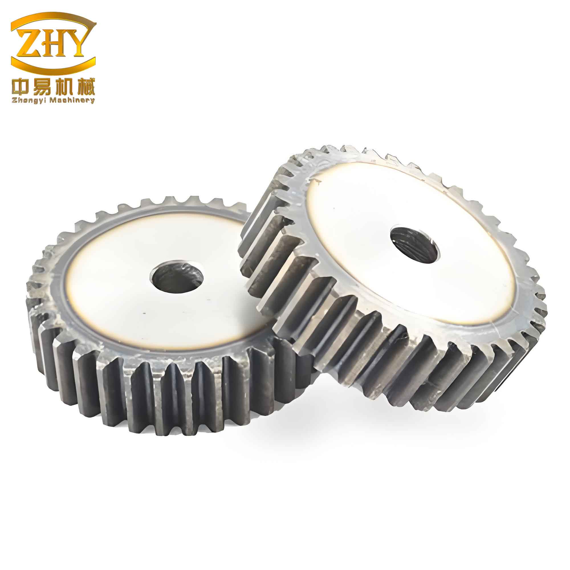
The following table summarizes the key geometric parameters for a standard, full-depth involute spur and pinion gear:
| Parameter | Symbol | Formula | Description |
|---|---|---|---|
| Module | m | Design Input (mm) | Defines the size of the tooth. The basic scaling parameter. |
| Number of Teeth | z | Design Input | Determines the size of the pitch circle. |
| Pressure Angle | α | Design Input (e.g., 20°) | Angle between the line of action and the line tangent to the pitch circle. |
| Pitch Diameter | d | $$d = m \cdot z$$ | The diameter of the imaginary circle where gear mesh is considered. |
| Base Circle Diameter | d_b | $$d_b = d \cdot \cos(\alpha)$$ | The circle from which the involute profile is generated. |
| Addendum | h_a | $$h_a = 1 \cdot m$$ | Radial distance from pitch circle to tooth tip. |
| Dedendum | h_f | $$h_f = 1.25 \cdot m$$ | Radial distance from pitch circle to tooth root. |
| Outside Diameter | d_a | $$d_a = d + 2 \cdot h_a$$ | Diameter of the gear’s outer circle. |
| Root Diameter | d_f | $$d_f = d – 2 \cdot h_f$$ | Diameter of the gear’s root circle. |
The mathematical definition of the involute curve is the cornerstone of parametric modeling. In parametric form (using an angle parameter θ), the coordinates of a point on the involute relative to the gear center are given by:
$$x(\theta) = r_b (\cos\theta + \theta \sin\theta)$$
$$y(\theta) = r_b (\sin\theta – \theta \cos\theta)$$
$$z(\theta) = 0$$
where:
$$r_b$$ is the base circle radius ($$r_b = \frac{d_b}{2}$$), and
$$\theta$$ is the involute roll angle in radians. This parametric equation will be directly implemented in NX using its “Law Curve” function.
Implementation of Parametric Modeling in NX
The process of building a parametric spur and pinion gear model in NX follows a logical, associative workflow. The goal is to create a model where every feature is linked back to a master set of parameters defined in the Expressions dialog.
Step 1: Defining Master Parameters with Expressions
The first and most critical step is to establish the driving parameters. In NX, navigate to Tools → Expressions. Here, we define all the variables listed in the geometric table. It is good practice to use descriptive names.
| Expression Name | Formula/Value | Comment |
|---|---|---|
| m | 3 [mm] | Module |
| z | 24 | Number of Teeth |
| alpha | 20 [deg] | Pressure Angle |
| face_width | 20 [mm] | Gear Width |
| d | m*z | Pitch Diameter |
| db | d*cos(alpha) | Base Circle Diameter |
| rb | db/2 | Base Circle Radius |
| da | d + 2*m | Outside Diameter |
| df | d – 2.5*m | Root Diameter |
Once these expressions are created, the entire model will reference these names (e.g., `da`) instead of hard-coded numbers. Changing the value of `m` or `z` here will propagate through all dependent formulas and, ultimately, the geometry.
Step 2: Creating the Involute Profile using a Law Curve
Since NX does not have a built-in “involute curve” command, we use the powerful Law Curve tool (Insert → Curve → Law Curve) to plot the parametric equations. We need to define laws for the X, Y, and Z components of the curve as functions of a temporary parameter, say `t`.
- Define the range for the parameter `t`. It must start at 0, but its end point should be large enough to generate the involute segment from the base circle to outside circle. A common method is to define an end angle in radians, e.g., `t_end = 60*pi/180` (60 degrees).
- For the X-coordinate law: `X(t) = rb * ( cos(t) + t * sin(t) )`.
- For the Y-coordinate law: `Y(t) = rb * ( sin(t) – t * cos(t) )`.
- For the Z-coordinate law: `Z(t) = 0`.
After defining these laws, NX generates the precise involute curve. This curve is associative, meaning if `rb` changes in the Expressions dialog, the curve will update automatically.
Step 3: Constructing a Single Tooth Space
With the involute curve created, the next step is to construct the 2D profile of one tooth gap (or space) on a datum plane.
- Create concentric circles for the root circle (diameter = `df`), base circle (`db`), and outside circle (`da`).
- Trim the involute curve using the root and outside circles as boundaries. You now have one flank of the tooth.
- Mirror this involute flank about the tooth centerline. The centerline is determined by the circular pitch: $$ \text{Tooth_Angle} = 360 / z $$. Half of this angle defines the centerline for mirroring.
- Close the profile by connecting the ends of the two involute segments with lines or arcs along the root circle and, if necessary, a tip arc along the outside circle. This creates a closed sketch profile representing one tooth space.
Step 4: Building the 3D Gear Body
The closed 2D profile is then extruded (`Insert → Design Feature → Extrude`) by the `face_width` parameter to create a single tooth space solid. The final step to create the complete spur and pinion gear blank is to use the circular pattern feature (`Insert → Associative Copy → Pattern Feature`).
- Select the extruded tooth space as the feature to pattern.
- Choose “Circular Pattern” as the pattern type.
- Specify the axis of rotation (the central axis of the gear).
- For the count, input the number of teeth `z`. The angular spacing will be automatically calculated as $$360/z$$ degrees.
NX will instantly create the full ring of tooth spaces. Finally, a simple cylinder representing the gear’s bore and hub can be added using the `d` and `da` parameters for reference, completing the parametric spur and pinion gear model.
Step 5: Driving Design Changes
The power of the parametric model is realized when a design change is required. For instance, to create a different spur and pinion gear for another stage in a gearbox, one simply needs to open the Expressions dialog and modify the driving parameters.
- To change the module to 4 mm and teeth to 18: Edit `m=4` and `z=18`.
- Upon clicking “OK,” NX automatically recalculates all dependent expressions (`d`, `db`, `da`, `df`, `Tooth_Angle`).
- Due to the associative links, all geometry—the law curve, the sketch, the extrusion, and the circular pattern—updates automatically to reflect the new size and geometry of the spur and pinion gear. This process takes seconds, compared to the hours required to remodel from scratch.
Advanced Applications and Integration
A parametric model is not merely a geometric representation; it serves as a digital twin that can be leveraged throughout the product lifecycle. For a spur and pinion gear, this is particularly valuable.
Finite Element Analysis (FEA) Integration
The parametric model can be directly used for structural and contact analysis in integrated CAE tools like NX Nastran or ANSYS Workbench. The associativity allows for design optimization studies:
- Parameter Study: An analyst can set up a study where the module (`m`), face width (`face_width`), or even root fillet radius (added as a new parameter) are defined as input variables.
- Goal: The goal could be to minimize mass while keeping the maximum contact stress below a material yield limit.
- Process: The optimization software automatically iterates through combinations of these parameters, updates the parametric CAD model for each iteration, runs the FEA mesh and solve, and extracts the results. This closed-loop process identifies the optimal gear dimensions without manual remodeling.
The bending stress at the root of a gear tooth can be estimated using the modified Lewis formula, which itself can be parameterized:
$$ \sigma_b = \frac{F_t}{b \cdot m \cdot Y} \cdot K_a \cdot K_v \cdot K_s $$
where parameters like tangential force ($$F_t$$), face width ($$b$$), and the geometry factor ($$Y$$, which depends on tooth shape) can all be linked to the model’s driving parameters for rapid “what-if” scenarios.
Computer-Aided Manufacturing (CAM)
For manufacturing, the parametric model ensures the CNC programming is always synchronized with the design. When the gear design is updated parametrically, the associated toolpaths for hobbing, shaping, or grinding can be regenerated automatically, as they reference the same updated solid geometry. This drastically reduces the risk of manufacturing errors and speeds up the transition from a revised design to production, which is essential for custom or low-volume spur and pinion gear manufacturing.
Conclusion
The parametric modeling of an involute spur and pinion gear in NX represents a fundamental best practice in modern mechanical design. By capturing design intent through a network of expressions and associative features, the model transcends being a static drawing and becomes a responsive, intelligent asset. The methodology outlined—from defining master parameters and law-based curve creation to associative patterning—provides a robust framework applicable to any standard gear design. The true value is unlocked when this parametric model is integrated into broader simulation and manufacturing workflows, enabling rapid prototyping, performance optimization, and seamless production. As CAD/CAE/CAM systems continue to evolve, mastering such parametric techniques remains essential for reducing development cycles, lowering costs, and innovating effectively in the design of power transmission components like the spur and pinion gear.