
In the field of precision motion control, particularly for robotic joints, the RV (Rotate Vector) reducer stands out as a critical component. Its design directly influences the performance, size, and cost of the final application. My primary objective as a design engineer is to develop an RV reducer that is not only reliable and efficient but also as compact and lightweight as possible. This drive for miniaturization is essential in modern robotics, where space constraints and the need for low inertia are paramount. This article details a systematic methodology I employ for the optimal tooth matching design of an RV reducer, with the explicit goal of minimizing its overall volume. The process integrates kinematic analysis, strength verification, and parametric optimization into a cohesive workflow.
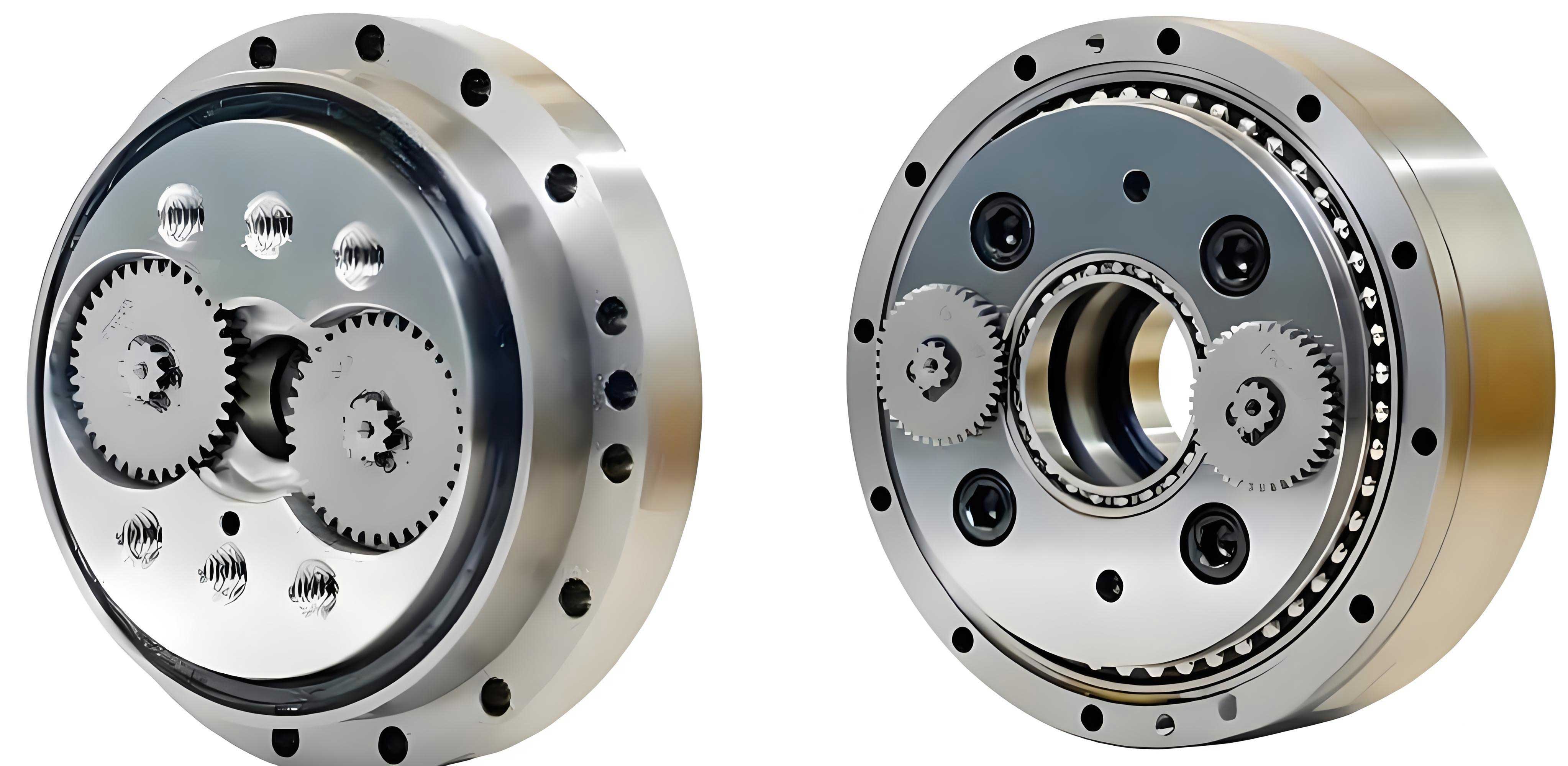
At its core, the RV reducer is a two-stage, closed differential planetary gear system. The first stage is a standard involute planetary gear train, and the second stage is a cycloidal pin-wheel planetary mechanism. This hybrid configuration is the source of its high reduction ratio, high torsional stiffness, and compact footprint. The main components include the sun gear (input), multiple planetary gears, a crank mechanism (connected to the planet gears), two cycloidal discs (offset by 180 degrees), a ring of stationary pins housed in a pin housing, and the output carrier. The power flow is as follows: the input sun gear drives the planetary gears. These planets rotate and, through the integrated crankshafts, impart an eccentric motion to the cycloidal discs. The meshing of the cycloidal discs with the stationary pins forces a slow revolution of the discs, which is then transferred to the output carrier. The unique advantage of the RV reducer lies in this force distribution across multiple contact points in the cycloidal stage, leading to high overload capacity and smooth operation.
The foundation of a compact RV reducer design is a correct and optimized tooth selection, often referred to as “tooth matching.” This is not a simple task of choosing arbitrary numbers; it is governed by a set of interlinked kinematic, geometric, and strength constraints that must be satisfied simultaneously. The goal is to find a combination of tooth counts for the sun gear ($$Z_1$$), planet gear ($$Z_2$$), and cycloidal disc ($$Z_4$$) or pin teeth ($$Z_5$$) that meets all functional requirements while laying the groundwork for a minimal volume. The primary constraints I must consider are:
1. Transmission Ratio Condition: The total reduction ratio ($$i$$) of the RV reducer with the pin housing fixed is given by:
$$ i = 1 + \frac{Z_5}{Z_1} \cdot \frac{Z_2}{Z_1 – Z_2} $$
Typically, the designed ratio should be very close to the target or nominal ratio ($$i_p$$), allowing only a minimal deviation:
$$ |i – i_p| / i_p \le 0.03 $$
2. Non-Undercutting Condition: To prevent gear tooth undercutting in the first-stage involute gears, the sun gear must have a sufficient number of teeth. For standard gear profiles, this requires:
$$ Z_1 \ge 17 $$
3. Load Distribution Condition: To ensure a balanced load on the second-stage cycloidal mechanism, the speed reduction of the first planetary stage should be limited. This is enforced by the condition on the first-stage gear ratio:
$$ \frac{Z_2}{Z_1} \le 4 $$
4. One-Tooth-Difference Condition: In the cycloidal stage, the tooth difference between the pin ring and the cycloidal disc must be exactly one for proper motion generation. This means the number of pins ($$Z_5$$) must be an even number, and the cycloidal disc tooth count is $$Z_4 = Z_5 – 1$$.
5. Structural Dimension Condition: The center distance ($$a_0$$) of the first-stage planetary gear must be proportional to the pin center circle radius ($$R_z$$) of the cycloidal stage to ensure proper force distribution on the crankshaft. An empirical relation is:
$$ a_0 = (0.5 \sim 0.6)R_z $$
where the pin center circle radius is related to the output torque ($$T$$). An empirical formula for initial sizing is:
$$ R_z \approx 25.4 \sqrt[3]{\frac{T}{\eta}} $$
Here, $$\eta$$ represents the overall transmission efficiency, calculated from the efficiencies of its components: bearing losses and gear meshing losses for both stages.
Manually iterating through all possible integer combinations of $$Z_1$$, $$Z_2$$, and $$Z_5$$ that satisfy these conditions is impractical. Therefore, I developed a computational tool using Visual Basic.NET to automate this search. The program algorithmically checks all constraints for a given range of tooth numbers and module size, generating a complete list of valid tooth combinations. For a module of $$m = 1.25 \text{ mm}$$, a subset of valid combinations is presented in the table below. This serialization of the tooth matching process is the first critical step toward optimization.
| Sun Gear Teeth ($$Z_1$$) | Planet Gear Teeth ($$Z_2$$) | Pin Teeth ($$Z_5$$) | Calculated Ratio ($$i$$) |
|---|---|---|---|
| 19 | 50 | 40 | 111.42 |
| 20 | 55 | 38 | 104.50 |
| 21 | 60 | 36 | 103.29 |
| 22 | 65 | 34 | 101.55 |
| 22 | 70 | 32 | 111.73 |
| 23 | 75 | 32 | 104.64 |
| 24 | 80 | 30 | 101.00 |
| 25 | 85 | 30 | 103.00 |
Once a valid tooth combination is selected, the next step is to determine the necessary face widths to ensure mechanical integrity. The first-stage gears are checked for both bending and contact fatigue strength.
Bending Fatigue Strength: The condition to prevent tooth breakage is $$\sigma_F \le [\sigma_F]$$. The required face width ($$b$$) derived from this condition is:
$$ b \ge \frac{2000 K_F T_1}{m^2 Z_1 Y_{Fa} Y_{Sa} [\sigma_F]} $$
where $$K_F$$ is the load factor, $$T_1$$ is the torque on the sun gear, $$Y_{Fa}$$ and $$Y_{Sa}$$ are the form and stress correction factors, and $$[\sigma_F]$$ is the allowable bending stress.
Contact Fatigue Strength: The condition to prevent pitting is $$\sigma_H \le [\sigma_H]$$. The required face width derived from the contact stress formula is:
$$ b \ge \left( \frac{Z_E Z_H Z_\epsilon}{[\sigma_H]} \right)^2 \sqrt[3]{\frac{2000 K_H T_1 (u+1)}{\psi_d u}} $$
Here, $$Z_E$$, $$Z_H$$, and $$Z_\epsilon$$ are the elasticity, zone, and contact ratio coefficients, $$K_H$$ is the contact load factor, $$u = Z_2/Z_1$$, $$\psi_d$$ is the face width coefficient, and $$[\sigma_H]$$ is the allowable contact stress. The final face width for the first-stage gears is the larger of the two values calculated from bending and contact conditions.
Cycloidal-Pin Contact Strength: The contact stress at the interface between the cycloidal disc and the pins must also be limited to prevent surface failures. The Hertzian contact stress formula is used. A simplified and conservative check for the required cycloidal disc width ($$B$$) can be expressed as:
$$ B \ge \frac{2000 T}{\eta \cdot 0.75 Z_5 R_z [\sigma_{HP}]} $$
where $$[\sigma_{HP}]$$ is the allowable contact stress for the cycloidal pair. Typically, $$B$$ is also proportionally related to the pin circle radius, often within $$B = (0.1 \sim 0.2)R_z$$.
With the tooth numbers selected and the necessary face widths calculated, the physical size of the RV reducer can be estimated. For optimization purposes, I use a simplified volumetric model that accounts for the major contributors to the overall envelope. The total approximate volume ($$V$$) is the sum of the volumes of the first-stage planetary gears (simplified as the sun gear volume) and the cycloidal stage components (cycloidal discs and the pin ring cylinder):
$$ V = V_1 + V_2 + V_3 $$
$$ V \approx \frac{\pi}{4} b m^2 Z_1^2 + \pi (e Z_4)^2 B + \pi R_z^2 B $$
Where:
- $$V_1$$: Volume estimate for the sun gear.
- $$V_2$$: Volume estimate for the two cycloidal discs (simplified as a cylinder with radius equal to the disc’s pitch radius $$r_b = e Z_4$$, where $$e$$ is the eccentricity).
- $$V_3$$: Volume estimate for the pin housing ring.
- $$b$$: Face width of the sun/planet gears.
- $$B$$: Face width of the cycloidal discs and pin ring.
This volume function $$V(Z_1, Z_2, Z_5, b, B)$$ becomes our objective function to minimize.
The optimization workflow is now fully parameterized. My VB.NET program loops through all valid tooth combinations from the initial matching table. For each combination $$(Z_1, Z_2, Z_5)$$:
- It calculates the center distance $$a_0 = m(Z_1+Z_2)/2$$ and the required pin radius $$R_z$$ from torque.
- It verifies the structural condition $$a_0 \approx 0.55 R_z$$. Combinations not meeting this within a tolerance are filtered out.
- For the remaining combinations, it calculates the required face widths $$b$$ and $$B$$ based on the strength equations.
- Finally, it computes the total volume $$V$$ using the simplified model.
The optimal design is identified as the valid tooth combination that yields the smallest calculated volume $$V$$.
To validate this methodology, I applied it to redesign a model analogous to a commercial RV reducer (e.g., RV110E type). The target specifications were: input power $$P = 2.26 \text{ kW}$$, input speed $$n = 15 \text{ rpm}$$, target reduction ratio $$i_p = 111$$, and gear module $$m = 1.25 \text{ mm}$$. The program scanned through numerous valid tooth sets. The results conclusively showed that the choice of tooth numbers has a significant impact on the theoretical volume. The optimization process successfully identified a specific combination that minimized the volume. A comparison between a baseline design and the optimized design is shown below:
| Parameter | Baseline Design | Optimized Design |
|---|---|---|
| Sun Gear Teeth ($$Z_1$$) | 21 | 22 |
| Planet Gear Teeth ($$Z_2$$) | 60 | 75 |
| Pin Teeth ($$Z_5$$) | 40 | 32 |
| Face Width, $$b$$ (mm) | 14.5 | 12.8 |
| Cycloidal Width, $$B$$ (mm) | 10.2 | 9.5 |
| Calculated Volume, $$V$$ (cm³) | 421.58 | 342.64 |
| Volume Reduction | – | 18.72% |
The results demonstrate the effectiveness of the proposed optimization approach. By systematically exploring the design space defined by the tooth matching constraints, I was able to identify a configuration that reduced the theoretical volume of the RV reducer by approximately 18.7%. This significant reduction translates directly into material savings, lower weight, and potentially a lower moment of inertia for the robotic joint. This automated, systematic process for RV reducer tooth matching and volume optimization proves to be a powerful tool in the design of compact and high-performance drive systems. It moves the design process from a trial-and-error approach to a targeted, computational search for the most efficient geometry, ensuring that the final RV reducer is not only functional but also optimally sized for its application.