
The advent of intelligent manufacturing has placed unprecedented demands on the precision, reliability, and development agility of core industrial components. Among these, the RV (Rotary Vector) reducer stands as a critical high-precision transmission component within robotic joints, directly influencing positioning accuracy, load capacity, and operational smoothness. Traditional design methodologies for RV reducers are often characterized by fragmented processes, reliance on disparate software tools, and repetitive manual calculations for variant development. This leads to protracted design cycles, heightened susceptibility to errors, and difficulty in rapidly responding to evolving market demands for customized or series products. To address these challenges, the development of an integrated, specialized digital design platform is imperative. This article details the conception, architectural design, and functional realization of such a comprehensive digital design platform specifically engineered for RV reducers. The platform aims to streamline the entire design workflow, from initial parameter calculation and structural optimization to automated drawing generation, thereby significantly enhancing design efficiency, ensuring consistency, and reducing time-to-market.
The RV reducer operates on a sophisticated two-stage reduction principle, combining a primary planetary gear stage with a secondary cycloidal (or摆线) pin-wheel stage. This architecture is renowned for achieving high reduction ratios, exceptional torsional stiffness, compact size, and high overload capacity within a single package. The design complexity arises from the intricate interaction between its numerous components, including the input gear, planetary gears, crankshafts, cycloidal disks (摆线轮), needle pins, and the output housing.
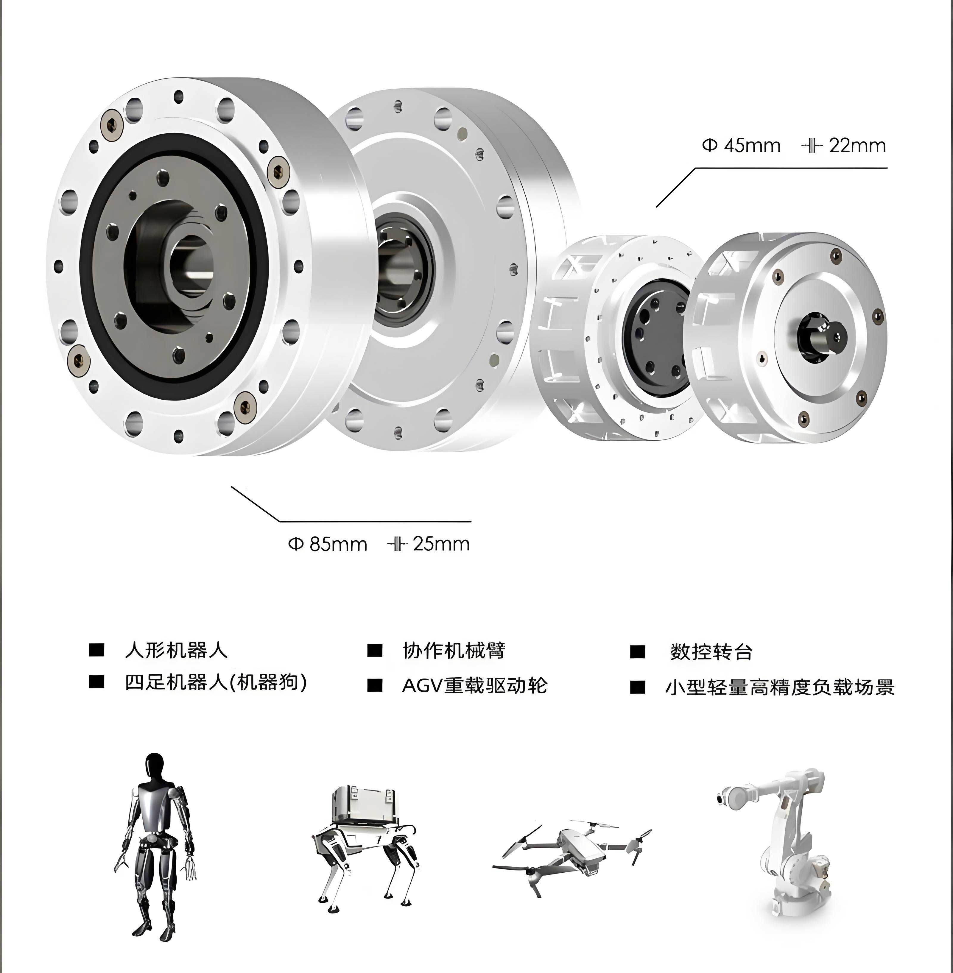
The fundamental kinematic relationship defining the reduction ratio ($i$) of a standard RV reducer is given by:
$$ i = 1 + \frac{Z_p}{Z_c} $$
where $Z_p$ is the number of needle pins in the housing and $Z_c$ is the number of teeth on the cycloidal disk. However, this simplified formula belies the multitude of interdependent parameters that require precise determination and optimization. Key design parameters encompass:
- Gear Parameters: Module, pressure angle, tooth profile modification coefficients for the planetary stage.
- Cycloidal Disk Parameters: Generating circle radius ($R_g$), pin circle radius ($R_p$), eccentricity ($e$), tooth profile modification for backlash and strength optimization.
- Structural Parameters: Dimensions of crankshafts, bearings, housing, and their respective wall thicknesses.
- Performance Constraints: Required output torque, torsional stiffness, rated input speed, lifetime (e.g., L10 bearing life), and efficiency.
Optimizing an RV reducer design involves navigating a complex multi-objective space where goals such as minimizing size and weight, maximizing stiffness and efficiency, and ensuring durability often conflict. A systematic, algorithm-driven approach within a unified digital environment is essential for finding optimal trade-offs.
Overall Architecture of the Digital Design Platform
The proposed digital design platform is architected as a modular, subsystem-based framework built upon a commercial CAD kernel (e.g., SolidWorks API) and integrated with computational engines (e.g., MATLAB). It facilitates a seamless flow from specification input to validated design output. The core philosophy is based on product platform and product family theories, enabling the efficient derivation of series variants from validated base models.
The platform’s architecture is composed of four primary, interacting subsystems:
| Subsystem | Core Function | Key Technologies |
|---|---|---|
| Platform Management Subsystem (PMS) | Serves as the central hub for user interaction, data orchestration, workflow control, and permission management. | Database management, Role-Based Access Control (RBAC), workflow engine, knowledge base integration. |
| Design & Calculation Subsystem (DCS) | Executes all parametric design logic, strength calculations, optimization algorithms, and kinematic/dynamic analysis for the RV reducer. | Parametric modeling, Finite Element Analysis (FEA) interfaces, mathematical optimization libraries, specialized RV reducer algorithms. |
| Drawing Optimization & Configuration Subsystem (DOCS) | Manages the automated generation, configuration, and batch processing of engineering drawings and manufacturing documentation. | Drawing template management, automated dimensioning, batch PDF/DXF export, title block configuration. |
| Underlying Support Subsystem (USS) | Provides the foundational software environment and data interfaces (CAD, CAE, Calculation Software). | CAD Application Programming Interface (API), data exchange protocols (e.g., XML, JSON), computational engine interfaces. |
The operational sequence within the platform typically follows this path: A designer initiates a project through the Platform Management Subsystem, selecting a base RV reducer product family. Initial requirements (torque, ratio, size constraints) are entered. The PMS fetches relevant template data and design rules, then invokes the Design & Calculation Subsystem. The DCS performs iterative calculations and optimizations, potentially calling external solvers via the Underlying Support Subsystem. Once a design is finalized, the PMS passes the parameter set to the Drawing Optimization & Configuration Subsystem, which populates drawing templates and prepares manufacturing documentation. All data, models, and documents are version-controlled and managed centrally by the PMS.
Platform Management Subsystem: The Command Center
The Platform Management Subsystem is the gateway and nervous system of the entire RV reducer digital design platform. It ensures data integrity, process adherence, and collaborative efficiency.
User and Permission Management
A robust Role-Based Access Control (RBAC) model is implemented. Different user roles have tailored permissions to ensure data security and process control.
| User Role | Primary Permissions | Design Data Access |
|---|---|---|
| System Administrator | Full system control, user creation/deletion, role definition, backup/restore. | Access to all projects and data. |
| Lead Designer | Create/manage projects, approve design releases, manage product structures and design rules. | Full access within assigned projects. |
| Design Engineer | Execute design tasks, run calculations, create and modify models and drawings. | Read/write access to specific task data. |
| Analyst / Checker | Perform verification analyses (FEA, interference), review and validate designs. | Read access for review; write access for analysis results. |
| Viewer / Client | Review finalized designs, specifications, and reports. | Read-only access to released documents. |
Product Data and Knowledge Management
This module manages the core intellectual assets related to the RV reducer platform.
- Product Structure Management: Defines and maintains the Bill of Materials (BOM) hierarchy for all RV reducer product families and variants. It links 3D part models, sub-assemblies, calculation files, and specifications to each node in the BOM tree.
- Design Rule Management: Encodes engineering knowledge and constraints into actionable rules. For example:
- Rule for minimum wall thickness of the housing based on output torque: $ t_{min} = k \cdot \sqrt[3]{T_{out}} + C $, where $k$ and $C$ are material constants.
- Rule for bearing selection based on crankshaft load and life requirement.
- Geometric constraints between cycloidal disk eccentricity and bearing size.
- Parameter Library Management: Maintains centralized libraries of standard parts (bearings, seals, fasteners), material properties, preferred numbers for key dimensions, and pre-calculated optimization results for common load cases.
Workflow and Process Management
The PMS enforces a standardized design process for the RV reducer, guiding the user through stages such as “Requirement Definition,” “Preliminary Sizing,” “Detailed Parameter Optimization,” “3D Modeling & Assembly,” “Engineering Analysis,” and “Drawing Release.” Each stage has defined inputs, required actions, and outputs, ensuring design consistency and completeness.
Design & Calculation Subsystem: The Computational Core
This subsystem embodies the engineering intelligence of the platform, automating the complex calculations specific to RV reducer design.
Parametric Design and Initial Sizing Module
Based on user-input requirements (e.g., Reduction Ratio $i$, Output Torque $T_{out}$, Input Speed $n_{in}$), this module performs first-pass sizing. It uses empirical formulas and lookup tables from the knowledge base to determine initial values for critical parameters like center distance, module, and approximate housing size. The fundamental torque relationship considering efficiency ($\eta$) is:
$$ T_{in} = \frac{T_{out}}{i \cdot \eta} $$
where $T_{in}$ is the required input torque.
Cycloidal Drive Detailed Design and Optimization Module
This is the most critical algorithmic component for the RV reducer. The tooth profile of the cycloidal disk is generated based on the equidistant offset of a shortened epicycloid. The parametric equations for the theoretical tooth profile are:
$$
\begin{aligned}
x &= (R_p – e \cdot \cos(\theta)) \cos(\phi) – (R_g – r_p) \cos(\theta – \phi) \\
y &= (R_p – e \cdot \cos(\theta)) \sin(\phi) + (R_g – r_p) \sin(\theta – \phi)
\end{aligned}
$$
where $\phi = \frac{Z_p}{Z_c} \theta$, $R_p$ is the pin circle radius, $R_g$ is the generating circle radius, $e$ is the eccentricity, $r_p$ is the needle pin radius, $Z_p$ is the number of pins, $Z_c$ is the number of cycloid teeth, and $\theta$ is the rotation parameter.
Optimization is performed on parameters like profile modification ($\Delta R_p$, $\Delta R_g$) to ensure proper backlash, load distribution, and strength. A multi-objective optimization problem can be formulated as:
$$
\begin{aligned}
\text{Minimize: } & f_1(\mathbf{x}) = \text{Contact Stress (赫兹应力)}, \quad f_2(\mathbf{x}) = \text{Size/Volume} \\
\text{Subject to: } & g_1(\mathbf{x}): \text{Backlash} \geq B_{min}, \\
& g_2(\mathbf{x}): \text{Torsional Stiffness} \geq K_{min}, \\
& g_3(\mathbf{x}): \text{Bending Stress} \leq \sigma_{allowable}, \\
& \mathbf{x} = [e, \Delta R_p, \Delta R_g, \text{…}]^T
\end{aligned}
$$
Algorithms such as NSGA-II (Non-dominated Sorting Genetic Algorithm II) are integrated to solve this and produce a Pareto front of optimal designs.
Strength Calculation and Verification Module
This module automates standard mechanical design checks:
- Bending and Contact Stress for Gears: Uses AGMA or ISO standards. For the planetary gears, bending stress is checked: $\sigma_F = \frac{F_t}{b m_n} Y_F Y_S Y_\beta K_A K_V K_{F\beta} K_{F\alpha}$.
- Bearing Life Calculation: Calculates the L10 life for the crankshaft bearings and main bearings using dynamic load ratings.
- Shaft (Crankshaft) Analysis: Performs static analysis for bending and torsion, calculating safety factors against yield. Combined stress is evaluated using the von Mises criterion: $\sigma’ = \sqrt{\sigma^2 + 3\tau^2}$.
- Housing Strength and Stiffness: Provides simplified analytical calculations for deflection under load, which is crucial for the overall torsional stiffness of the RV reducer.
3D Parametric Modeling and Automatic Assembly
Once parameters are optimized, this module drives the CAD software via API to regenerate all 3D part models. A master model technique is used, where a single set of driving parameters controls the geometry of all components. The subsystem then automatically assembles the parts, respecting mates and constraints defined in the template. This ensures that any change in a core parameter (e.g., number of teeth) automatically updates the entire RV reducer assembly model correctly.
Interference Check and Kinematic Simulation Module
After assembly regeneration, an automatic global interference check is performed within the CAD environment to detect any geometric clashes—a common issue in compact, complex assemblies like the RV reducer. A simplified kinematic simulation can also be run to verify the motion of the cycloidal disks and planetary gears, ensuring no binding occurs throughout the rotation cycle.
Drawing Optimization & Configuration Subsystem
This subsystem bridges the digital design and manufacturing phases by automating the creation of production documentation.
Drawing Template Management
A library of standardized drawing templates is maintained for every part and assembly in the RV reducer family. These templates contain pre-defined views, tables (title block, BOM), and annotation styles. They are parameterized, with links to the model’s driving parameters and custom properties.
Automatic Drawing Generation and Configuration
When a design is finalized, the DOCS retrieves the 3D model and its associated parameter set. It then:
- Opens the appropriate drawing template.
- Populates the views with the current model geometry.
- Runs automated dimensioning scripts to apply critical dimensions and tolerances based on rules (e.g., fit tolerances for bearing seats, gear tooth specifications).
- Fills in the title block, part number, material, and other annotations directly from the model’s properties.
- Updates the Bill of Materials table automatically.
Batch Processing and Export
For a complete RV reducer design comprising dozens of parts, the DOCS can batch-process all drawings in one operation. It can automatically:
- Generate PDFs for all drawings for review and distribution.
- Export DXF/DWG files of specific layers for CNC machining.
- Print full drawing sets to designated plotters or printers.
This eliminates the tedious, error-prone manual process of creating and managing hundreds of individual drawing files.
Key Algorithmic Implementations and Integration
The platform’s effectiveness hinges on several sophisticated, integrated algorithms.
Parametric Modeling and Linkage Update Mechanism
A robust data linkage is established to ensure consistency. A central spreadsheet or database table acts as the “master parameter table.” Changes here trigger a cascade of updates:
- The DCS re-executes relevant calculations if the changed parameter is a driving input.
- The updated parameters are pushed to the 3D CAD model via API, triggering regeneration of parts and assembly.
- The regenerated assembly’s mass properties are calculated and fed back to the DCS for verification (e.g., inertia check).
- Finally, the DOCS is signaled to update all associated drawings with the new geometry and properties.
This closed-loop, associative design environment is fundamental to the platform’s efficiency.
Integration of Multi-Objective Optimization (MOO)
The integration of MOO algorithms like NSGA-II allows designers to explore the trade-offs inherent in RV reducer design. The platform provides a dedicated interface to define objectives (minimize mass, maximize stiffness), constraints (stress limits, minimum size), and design variables (continuous and discrete). After the optimization run, results are presented in a Pareto chart, and the designer can select a preferred solution point. The parameters of this chosen point are automatically loaded as the new design version.
Automated Interference Checking and Reporting
The interference check is not a one-time event but an integrated step in the update cycle. After every significant parameter change and model regeneration, a lightweight interference detection script runs. It generates a report listing any interfering components and the volume of interference. For common, known interferences that appear under certain parameter combinations, the platform can even embed preventive rules to adjust parameters automatically to avoid the clash.
Application Validation and Operational Benefits
The deployment of this RV reducer digital design platform has demonstrated substantial improvements across the design process. The table below contrasts key metrics between the traditional design approach and the platform-assisted approach for developing a new variant.
| Design Phase / Metric | Traditional Approach | Platform-Assisted Approach | Improvement / Benefit |
|---|---|---|---|
| Preliminary Sizing & Calculation | Manual lookups, spreadsheet calculations, prone to copy-paste errors; ~2-3 days. | Automated calculation modules with integrated rules; ~2 hours. | ~90% time reduction, elimination of calculation errors. |
| Parameter Optimization | Iterative manual trials, limited exploration of design space. | Systematic MOO algorithms exploring 1000s of configurations automatically. | Higher performance designs, discovery of non-intuitive optimal solutions. |
| 3D Modeling & Assembly | Manual (re)drawing of parts, manual assembly mating; ~1 week. | Fully automatic parametric regeneration and assembly; ~1 hour. | ~95% time reduction, guaranteed geometric consistency. |
| Drawing Creation | Manual creation/updating of each drawing; highly time-consuming and error-prone. | Fully automatic generation and configuration from templates. | Near 100% time reduction, standardization, zero annotation errors from model. |
| Design Cycle for a New Variant | Several weeks to months. | Few days to a week. | Dramatically faster time-to-market, enhanced agility. |
| Knowledge Retention & Reuse | Relies on individual experience; difficult to transfer. | Encoded in design rules, templates, and parameter libraries. | Preserves corporate knowledge, enables consistent best practices. |
Furthermore, the platform ensures that every RV reducer design adheres to the company’s internal standards and validation protocols. By automating routine and complex tasks, it allows experienced engineers to focus on high-level design innovation, problem-solving, and addressing truly novel challenges, rather than getting bogged down in repetitive calculations and drafting.
Conclusion and Future Directions
The development and application of this integrated digital design platform represent a significant advancement in the methodology for designing RV reducers. By synthesizing product platform theory, advanced parametric modeling, multi-objective optimization, and automated document management into a cohesive system, the platform effectively addresses the key challenges of design complexity, development speed, and quality consistency. It transforms the design process from a sequential, manual, and error-prone activity into a highly automated, associative, and optimized workflow. The platform has proven its value in significantly shortening product development cycles, reducing design costs, and improving the overall quality and performance robustness of the resulting RV reducer variants.
Future development of the platform will focus on several advanced frontiers. Deepening the integration of high-fidelity simulation, such as dynamic Multibody System (MBS) analysis for vibration and detailed nonlinear Finite Element Analysis (FEA) for contact stresses and fatigue life, will move the platform from a design tool to a high-fidelity virtual prototyping environment. The incorporation of machine learning algorithms could further accelerate the design process, for instance, by using surrogate models trained on past optimization runs to predict optimal starting points or by automatically classifying and resolving common interference patterns. Furthermore, extending the platform’s scope to encompass a full digital thread—linking the finalized digital design directly to CAM programming for machining, to inspection plans for CMMs, and even to performance monitoring data from fielded RV reducers—will close the loop between design, manufacturing, and operational feedback, paving the way for truly data-driven, continuous product improvement cycles for the RV reducer and similar complex mechanical systems.