
In the field of precision robotics and high-torque transmission systems, the Rotary Vector (RV) reducer stands out as a critical component. Its compact design, high reduction ratio, excellent load-bearing capacity, and superior positioning accuracy make it indispensable for robot joints, aerospace actuators, and heavy-duty machinery. The unique two-stage reduction mechanism of the RV reducer, combining a first-stage planetary gear train with a second-stage cycloid-pin drive, is the source of its exceptional performance. However, the dynamic behavior of the RV reducer, which directly influences its vibration, noise, and operational stability, is a complex phenomenon heavily dependent on the stiffness characteristics of its components. Among these, the stiffness of the second-stage cycloid-pin transmission, often referred to as the pin-cycloid transmission, is paramount. This study focuses on establishing a refined analytical model for the equivalent torsional meshing stiffness of this transmission, a parameter crucial for accurate dynamic modeling and simulation of the entire RV reducer system.
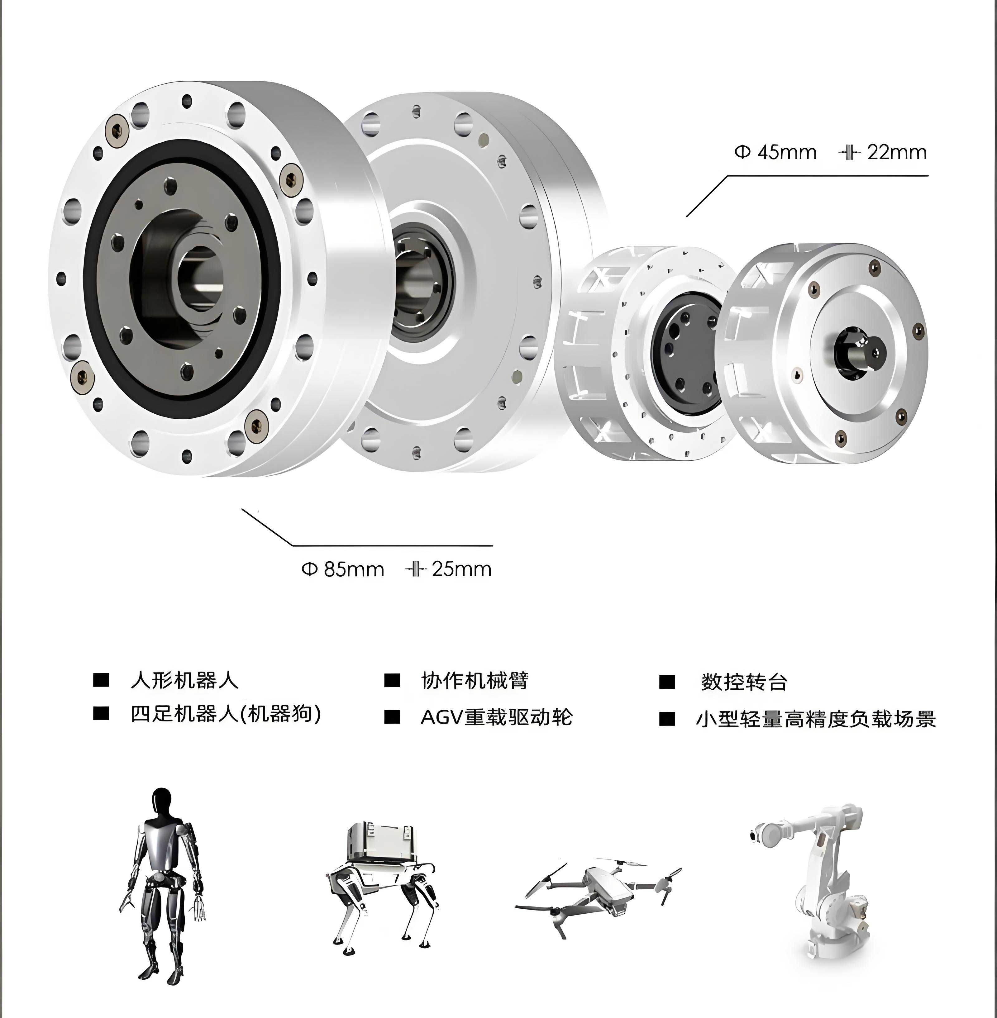
The dynamic performance of an RV reducer is fundamentally linked to its stiffness matrix. An accurate representation of the stiffness, particularly the time-varying or position-varying meshing stiffness, is essential for predicting natural frequencies, avoiding resonant conditions, and optimizing the design for minimal vibration and acoustic emission. Within the RV reducer, the cycloid disk engages with multiple stationary pin gears housed in a pin wheel. In an ideal theoretical scenario with perfect geometry, nearly half of the pins would be in contact at any given time. Practically, to accommodate lubrication and compensate for manufacturing errors, the cycloid tooth profile is always modified through methods like equidistant or offset profile shifting. These modifications create initial clearance between the cycloid disk and the pins, significantly reducing the number of pins that actually share the load during operation. Therefore, a realistic stiffness model for the RV reducer must account for this variable number of contacting teeth.
Previous research has laid important groundwork. Studies have focused on calculating the actual number of meshing teeth under load, deriving formulas based on force equilibrium and elastic deformation. Others have applied Hertzian contact theory to compute the contact stiffness between a single cycloid tooth and a pin. Furthermore, investigations have explored the equivalent torsional stiffness of the cycloid drive under various profile modifications and analyzed the overall RV reducer’s torsional stiffness variation. A critical aspect often simplified in these models is the treatment of the local contact geometry. The curvature of the cycloid profile is not constant; it varies significantly along the tooth flank and can even change sign, indicating a transition from convex-to-convex contact to convex-to-concave contact between the pin and the cycloid tooth. This variation directly impacts the local contact stiffness according to Hertzian theory. A model that assumes a constant effective curvature may introduce errors in the calculated stiffness values.
In this study, I establish a comprehensive analytical model for the equivalent torsional meshing stiffness of the pin-cycloid transmission within an RV reducer. The model explicitly incorporates the continuous variation of the cycloid tooth’s radius of curvature at each potential contact point. I derive the functional relationship between the meshing point position and the local contact stiffness based on Hertzian theory, carefully distinguishing between the two contact states. This single-tooth stiffness is then converted into a torsional stiffness contribution relative to the cycloid disk’s center. Concurrently, a force-deformation model for the loaded cycloid disk is used to determine the actual set of pins in contact for a given input torque, considering profile modifications. By summing the torsional stiffness contributions from all active contact pairs, I obtain the instantaneous equivalent torsional meshing stiffness of the transmission as a function of the crank shaft’s rotation angle. Using numerical simulation, I analyze the variation pattern of this stiffness and investigate the influence of different input torque levels on its magnitude and fluctuation characteristics. The findings from this analysis provide valuable insights for the precise dynamic modeling and design optimization of RV reducers.
Theoretical Foundation: Hertzian Contact and Curvature Analysis
The contact between a pin and a cycloid tooth in an RV reducer, though theoretically a line contact, is treated as the contact between two cylindrical bodies due to elastic deformation. The Hertzian contact theory provides the fundamental framework for analyzing this interaction. Consider two elastic cylinders with radii \(\rho_1\) and \(\rho_2\), pressed together by a force \(F\) per unit face width \(b\). The half-width \(L\) of the contact area is given by:
$$L = \sqrt{ \frac{4F}{\pi b} \cdot \frac{1-\mu_1^2}{E_1} + \frac{1-\mu_2^2}{E_2} \over \frac{1}{\rho_1} \pm \frac{1}{\rho_2} }$$
where \(E_1, E_2\) are the Young’s moduli and \(\mu_1, \mu_2\) are the Poisson’s ratios of the pin and cycloid materials, respectively. The sign in the denominator is positive for convex-convex contact (both surfaces convex outward) and negative for convex-concave contact.
In a typical RV reducer, the pin and the cycloid disk are made from the same material (e.g., bearing steel). Therefore, we can simplify by setting \(E_1 = E_2 = E\) and \(\mu_1 = \mu_2 = \mu\). Defining the equivalent radius \(\rho\) as \(\frac{1}{\rho} = \frac{1}{\rho_1} \pm \frac{1}{\rho_2}\), the formula simplifies to:
$$L = \sqrt{ \frac{8 F \rho (1-\mu^2)}{\pi b E} }$$
For the pin, the radius \(\rho_1\) is constant and equal to the pin radius \(r_{rp}\). The challenge lies in determining \(\rho_2\), the radius of curvature of the cycloid tooth at the specific contact point. The theoretical radius of curvature \(\rho_0\) for a standard cycloid profile (before modification) is derived from its parametric equations:
$$\rho_0(\varphi_i) = \frac{r_p (1 + K_1^2 – 2K_1 \cos\varphi_i)^{3/2}}{K_1(z_p + 1)\cos\varphi_i – (1 + z_p K_1^2)}$$
where:
\(r_p\) is the radius of the pin center circle.
\(z_p\) is the number of pins.
\(K_1 = a z_p / r_p\) is the shortening coefficient.
\(a\) is the eccentricity of the crank shaft.
\(\varphi_i\) is the angular parameter (relative to the crank arm) defining the position of the \(i\)-th pin.
The sign of \(\rho_0\) determines the local concavity of the cycloid profile. A positive \(\rho_0\) indicates a concave surface (the center of curvature lies inside the material), leading to convex-concave contact with the pin. A negative \(\rho_0\) indicates a convex surface, leading to convex-convex contact. The actual radius \(\rho_2\) used in Hertz’s formula must account for the profile modification. For the common case of equidistant modification \(\Delta r_{rp}\), the effective radius becomes \(\rho_2 = \rho_0 + r_{rp} + \Delta r_{rp}\). For analysis, we consider the nominal profile, setting \(\rho_2 = \rho_0 + r_{rp}\). The contact condition is then determined by the composite curvature:
$$\frac{1}{\rho} = \frac{1}{r_{rp}} \pm \frac{1}{\rho_2}$$
Using the geometry of the deformed cylinders, the approximate normal approach (mutual compression) \(\delta\) between the two bodies can be derived. For the pin’s contribution \(c_r\), it is found to be:
$$c_r \approx \frac{4F\rho (1-\mu^2)}{\pi b E r_{rp}}$$
Thus, the stiffness contribution from the pin’s deformation is:
$$k_r = \frac{F}{c_r} = \frac{\pi b E r_{rp}}{4\rho (1-\mu^2)}$$
Similarly, the stiffness contribution from the deformation of the cycloid tooth at the contact point is:
$$k_c = \frac{F}{c_c} \approx \frac{\pi b E \rho_2}{4\rho (1-\mu^2)}$$
The combined meshing stiffness for a single pin-cycloid tooth pair, considering both bodies in series, is:
$$k_i = \left( \frac{1}{k_r} + \frac{1}{k_c} \right)^{-1} = \frac{\pi b E}{4(1-\mu^2)} \cdot \frac{r_{rp} \rho_2}{r_{rp} + \rho_2}$$
Substituting the expression for \(\rho_2\) and carefully handling the sign of \(\rho_0\) based on the contact state, we obtain two cases. Defining \(S = 1 + K_1^2 – 2K_1 \cos\varphi_i\) and \(T = K_1(z_p+1)\cos\varphi_i – (1+z_p K_1^2)\):
- For convex-concave contact (\(\rho_0 > 0\), \(\rho_2 > r_{rp}\)):
$$k_i = \frac{\pi b E r_p S^{3/2}}{4(1-\mu^2) \left( r_p S^{3/2} + 2T r_{rp} \right)}$$
- For convex-convex contact (\(\rho_0 < 0\), \(\rho_2\) is negative in value but used as its absolute magnitude in the series formula):
$$k_i = \frac{\pi b E }{4(1-\mu^2)}$$
This reveals a significant insight: in the convex-convex contact regions of the cycloid tooth, the local pair stiffness approaches a constant material-dependent value, independent of the contact position parameter \(\varphi_i\).
Modeling the Loaded Pin-Cycloid Transmission
Determination of Active Meshing Teeth
Due to profile modifications, there exists an initial clearance \(\Delta(\varphi_i)\) along the common normal direction between the unloaded cycloid disk and each pin. This clearance is a function of the modification parameters (\(\Delta r_{rp}\) for equidistant, \(\Delta r_p\) for offset modification) and the geometry:
$$\Delta(\varphi_i) = \Delta r_{rp} \left(1 – \frac{\sin\varphi_i}{\sqrt{1 + K_1^2 – 2K_1 \cos\varphi_i}} \right) – \frac{\Delta r_p \left(1 – K_1 \cos\varphi_i – \sqrt{1-K_1^2} \sin\varphi_i \right)}{\sqrt{1 + K_1^2 – 2K_1 \cos\varphi_i}}$$
Under no load, only the pin(s) with near-zero clearance make contact. When an output torque \(T_c\) is applied to the cycloid disk, it rotates slightly through an angle \(\beta\) due to the combined elastic deformation at all contact points (including pin compression and housing deformation). This rotation causes a displacement \(\delta_i\) along the potential contact normal direction for the \(i\)-th pin:
$$\delta_i = l_i \beta$$
Here, \(l_i\) is the distance from the cycloid disk center \(O_c\) to the line of action (common normal) for the \(i\)-th pin pair. It is given by:
$$l_i(\varphi_i) = r_c \frac{\sin\varphi_i}{\sqrt{1 + K_1^2 – 2K_1 \cos\varphi_i}}$$
where \(r_c\) is the radius of the cycloid disk’s rolling circle. A pin \(i\) becomes an active load-bearing element if the induced displacement exceeds the initial clearance:
$$\delta_i > \Delta(\varphi_i)$$
By solving this inequality for a given load (which relates to \(\beta\)), we find the angular range \([\varphi_m, \varphi_n]\) where pins are in contact. The actual number of meshing teeth \(N\) is then:
$$N = \text{int}\left( \frac{z_p}{2} \cdot \frac{\varphi_n – \varphi_m}{180} \right)$$
This number \(N\) is a function of the applied torque, increasing with higher loads as more pins overcome their initial clearance.
Equivalent Torsional Meshing Stiffness
The single-pair stiffness \(k_i\) is a translational stiffness along the line of action. To find its contribution to the torsional stiffness of the cycloid disk, we consider virtual work. A virtual rotation \(d\theta\) of the disk causes a displacement \(ds_i = l_i d\theta\) at the \(i\)-th contact point. The resulting force is \(dF_i = k_i \cdot ds_i = k_i l_i d\theta\). The corresponding contribution to the resisting torque is \(d\tau_i = l_i \cdot dF_i = k_i l_i^2 d\theta\). Therefore, the torsional stiffness contribution of the \(i\)-th pair is:
$$k_i^T = \frac{d\tau_i}{d\theta} = k_i l_i^2$$
The total equivalent torsional meshing stiffness \(K_{eq}\) of the pin-cycloid transmission at a given crank shaft position (which defines the set of \(\varphi_i\) for all pins) is the sum of contributions from all active pins (\(m\) to \(n\)):
$$K_{eq} = \sum_{i=m}^{n} k_i^T = \sum_{i=m}^{n} k_i(\varphi_i) \cdot \left[ l_i(\varphi_i) \right]^2$$
As the crank shaft rotates, the set of angles \(\varphi_i\) for each fixed pin relative to the moving cycloid disk changes periodically. Consequently, both the set of active pins and the individual \(k_i\) and \(l_i\) values for those pins change, making \(K_{eq}\) a periodic function of the crank shaft’s rotation angle \(\theta_{crank}\). This time-varying stiffness is a key excitation source for vibrations in the RV reducer.
Numerical Instance and Analysis
To demonstrate the application of the developed model, I perform a numerical analysis based on the parameters of a heavy-duty RV-550E type reducer. The key parameters are summarized in the table below.
| Parameter | Symbol | Value | Unit |
|---|---|---|---|
| Number of Pins | \(z_p\) | 60 | – |
| Pin Center Circle Radius | \(r_p\) | 165 | mm |
| Pin Radius | \(r_{rp}\) | 5 | mm |
| Cycloid Disk Width | \(b\) | 25 | mm |
| Crank Eccentricity | \(a\) | 2.2 | mm |
| Young’s Modulus | \(E\) | 2.06e11 | Pa |
| Poisson’s Ratio | \(\mu\) | 0.3 | – |
| Equidistant Modification | \(\Delta r_{rp}\) | 0.02 | mm |
| Offset Modification | \(\Delta r_p\) | 0.03 | mm |
First, the single-pair torsional stiffness \(k_i^T = k_i l_i^2\) is computed over a full range of \(\varphi_i\). The result, shown conceptually, exhibits a highly nonlinear curve. It features regions of relatively constant, high stiffness (corresponding to convex-convex contact zones) and regions where stiffness drops significantly (corresponding to convex-concave contact zones where \(\rho\) becomes larger).
Next, the model is used to analyze the effect of input torque. Three different input torque levels are considered: 4607 N·m, 6866 N·m, and 9310 N·m. For each torque, the corresponding deformation rotation \(\beta\) is calculated based on force equilibrium, and the inequality \(\delta_i > \Delta(\varphi_i)\) is solved to find the active pins. The relationship is illustrated schematically by plotting the initial clearance curve \(\Delta(\varphi_i)\) and the linear displacement line \(\delta_i = l_i \beta\) for different \(\beta\) values. The intersection points define \(\varphi_m\) and \(\varphi_n\). The results for the number of meshing teeth are:
| Input Torque | Active Meshing Teeth Count (N) |
|---|---|
| 4607 N·m | 17 |
| 6866 N·m | 19 |
| 9310 N·m | 20 |
The calculation process for the equivalent stiffness \(K_{eq}(\theta_{crank})\) is implemented in a computational algorithm. The crank shaft rotation is discretized. For each angular position \(\theta_{crank}\), the corresponding \(\varphi_i\) for all pins is calculated based on the kinematic relationship of the RV reducer. The active pins are identified using the loaded model for the current torque. For each active pin, its \(\varphi_i\) is used to compute \(k_i(\varphi_i)\) and \(l_i(\varphi_i)\), and its contribution \(k_i^T\) is summed. This process yields the periodic stiffness curve \(K_{eq}(\theta_{crank})\).
The resulting equivalent torsional meshing stiffness curves for the three torque levels are plotted together. The analysis reveals several critical characteristics of the RV reducer’s pin-cycloid transmission stiffness:
- Periodicity: \(K_{eq}\) varies periodically with a period equal to one revolution of the crank shaft (\(360^\circ\)). This periodicity is a fundamental source of parametric excitation in the RV reducer’s dynamics.
- Torque Dependency: The magnitude of the stiffness fluctuation is torque-dependent. Higher input torque generally leads to a higher mean and peak stiffness because more pins participate in load sharing. However, the relationship is nonlinear.
- Waveform Complexity: The stiffness curve is not a simple sinusoid. It exhibits sharp transitions and plateaus. These features are direct consequences of the discrete nature of pin engagement/disengagement and the nonlinear variation of single-pair stiffness \(k_i\) with \(\varphi_i\). The “constant stiffness” zones from convex-convex contact create flat sections in the overall curve.
- Torque-Specific Interactions: At certain crank angles (e.g., between \(35^\circ-95^\circ\) and \(230^\circ-265^\circ\) in the example), the stiffness values for different torques may coincide. This occurs because the additional pins engaged at higher torque in these angular regions happen to be in positions where their individual stiffness contribution \(k_i^T\) is near its minimum, thus adding little to the total sum. Conversely, in other ranges (e.g., \(265^\circ-350^\circ\)), the engagement of new pins at higher torque adds contributions from pins whose stiffness is changing rapidly, leading to more pronounced oscillations and a wider envelope of stiffness variation.
The pronounced fluctuation in meshing stiffness, often exceeding 20-30% of the mean value, acts as a time-varying parameter in the system’s differential equations of motion. This can lead to complex dynamic phenomena, including parametric resonances, which must be considered during the design phase of the RV reducer to ensure smooth and quiet operation.
Conclusion and Implications for RV Reducer Design
In this analysis, I have developed and demonstrated a refined model for calculating the equivalent torsional meshing stiffness of the cycloid-pin transmission in an RV reducer. The primary advancement of this model is the explicit incorporation of the cycloid tooth’s variable radius of curvature and the consequent distinction between convex-convex and convex-concave contact states in the Hertzian stiffness calculation. This provides a more physically accurate representation of the local contact mechanics compared to models assuming constant effective curvature.
The integrated model, which combines this detailed contact stiffness model with a load-dependent kinetostatic model for determining active meshing teeth, successfully captures the essential characteristics of the transmission’s stiffness behavior. The numerical results clearly show that the equivalent torsional stiffness is a periodic, torque-amplitude-dependent function of the crank shaft angle. Key features such as stiffness plateaus (from constant-curvature contact zones) and sharp transitions (from teeth engaging/disengaging) are revealed.
The implications for RV reducer dynamics and design are significant:
- Accurate Dynamic Modeling: The derived stiffness function \(K_{eq}(\theta, T)\) can be directly incorporated into lumped-parameter or finite element dynamic models of the RV reducer. This allows for more precise prediction of natural frequencies, vibration modes, and forced response under operational loads, enabling designers to avoid resonant conditions.
- Understanding Excitation Sources: The periodic fluctuation of stiffness is a major internal excitation mechanism causing vibration and noise. Quantifying this fluctuation helps in assessing the vibratory energy input and guiding noise-reduction strategies, such as optimizing profile modification to minimize stiffness variation or designing damping elements.
- Influence of Load: The model demonstrates that the stiffness characteristic is not static but changes with the applied torque. This nonlinear behavior must be considered in high-fidelity simulations, especially for applications involving highly variable loads, to ensure predictive accuracy across the entire operating envelope.
- Design Optimization Guidance: The analysis framework can be used as a tool to evaluate the impact of geometric parameters (e.g., pin radius, eccentricity, modification amounts) on the stiffness curve. Designers can iteratively adjust these parameters to achieve a desired stiffness characteristic—for example, minimizing the peak-to-peak variation to reduce vibration excitation or maximizing the mean stiffness for higher positional rigidity.
Future work could extend this model by incorporating the flexibility of other components in the RV reducer, such as the crankshaft, planet gears, and bearings, to build a comprehensive system-level stiffness matrix. Furthermore, the validation of the predicted stiffness curves against experimental measurements from strain gauges or torsional vibration tests would be a valuable step. Nevertheless, the presented analysis provides a robust theoretical and methodological foundation for understanding and modeling the crucial stiffness properties of the pin-cycloid transmission, contributing to the ongoing advancement of high-performance, reliable RV reducers.