
In mechanical transmission systems, straight spur gears are among the most critical components due to their high efficiency, precise transmission ratio, long service life, and wide power range. During operation, these gears inevitably experience mechanical vibrations induced by various excitations such as meshing impacts, transmission errors, and external dynamic loads. The vibration characteristics of straight spur gears are intrinsic dynamic properties that significantly influence the system’s dynamic response, load generation and transfer, and overall vibration modes. In the initial design phase of a gear, it is often challenging to predict its natural vibration behavior without detailed analysis. Therefore, it is essential to employ finite element methods to investigate the natural characteristics of straight spur gears. This study focuses on the modal analysis of a typical straight spur gear used in a coal mining vehicle transmission system. By utilizing the ANSYS finite element software, we establish a three-dimensional solid model and perform a modal analysis to extract the low-order natural frequencies and corresponding mode shapes. The results provide theoretical guidance for the dynamic analysis and optimization design of straight spur gears.
Introduction
Gears are fundamental elements in power transmission and motion control. Among various gear types, straight spur gears are widely applied in automotive, mining, and industrial machinery due to their simple geometry and ease of manufacturing. However, gear noise and vibration remain persistent engineering challenges. The natural frequencies and mode shapes of straight spur gears are key parameters that dictate the resonance conditions and dynamic amplification factors. If the excitation frequency approaches any natural frequency, severe resonance may occur, leading to increased noise, accelerated wear, and even catastrophic failure. Therefore, understanding the modal characteristics of straight spur gears is crucial for designing robust and reliable gear systems.
Traditional analytical methods for gear vibration often rely on simplified lumped-parameter models that neglect the continuous mass and stiffness distribution of the gear body. With the advancement of computational mechanics, the finite element method (FEM) has become a powerful tool for predicting the dynamic behavior of complex structures. By discretizing the gear geometry into a finite number of elements, we can account for the actual material properties, boundary conditions, and geometric details. In this work, we adopt a three-dimensional solid modeling approach using ANSYS to simulate the free vibration of a straight spur gear. The low-order modal parameters are extracted and analyzed, forming a basis for subsequent dynamic response calculations and structural optimization.
Theoretical Model of Modal Analysis
The dynamic behavior of a linear elastic structure subjected to external forces can be described by the general equation of motion:
$$ \mathbf{M} \ddot{\mathbf{x}}(t) + \mathbf{C} \dot{\mathbf{x}}(t) + \mathbf{K} \mathbf{x}(t) = \mathbf{q}(t) $$
where \(\mathbf{M}\), \(\mathbf{C}\), and \(\mathbf{K}\) are the mass, damping, and stiffness matrices of the system, respectively; \(\mathbf{x}(t)\) is the displacement vector; \(\dot{\mathbf{x}}(t)\) and \(\ddot{\mathbf{x}}(t)\) are the velocity and acceleration vectors; and \(\mathbf{q}(t)\) is the vector of applied nodal forces. For modal analysis, we are interested in the free vibration characteristics, i.e., the solution when no external force is applied and damping is neglected. In that case, the equation reduces to the undamped free vibration form:
$$ \mathbf{M} \ddot{\mathbf{x}}(t) + \mathbf{K} \mathbf{x}(t) = \mathbf{0} $$
Assuming a harmonic solution: \(\mathbf{x}(t) = \boldsymbol{\phi} e^{i \omega t}\), where \(\boldsymbol{\phi}\) is the mode shape vector and \(\omega\) is the circular frequency, we obtain the eigenvalue problem:
$$ \left( \mathbf{K} – \omega^2 \mathbf{M} \right) \boldsymbol{\phi} = \mathbf{0} $$
The eigenvalues \(\omega_i^2\) correspond to the squares of natural frequencies, and the eigenvectors \(\boldsymbol{\phi}_i\) represent the corresponding mode shapes. In practice, only the first few modes are of engineering interest because higher modes usually have negligible contribution to the overall dynamic response under typical operating conditions. The mass matrix \(\mathbf{M}\) and stiffness matrix \(\mathbf{K}\) are assembled from element matrices:
$$ \mathbf{M} = \sum_{e} \mathbf{M}_e, \quad \mathbf{K} = \sum_{e} \mathbf{K}_e $$
For a solid element, the element mass matrix is given by:
$$ \mathbf{M}_e = \int_{V_e} \rho \mathbf{N}^T \mathbf{N} \, dV $$
where \(\rho\) is the material density and \(\mathbf{N}\) is the shape function matrix. Similarly, the element stiffness matrix is:
$$ \mathbf{K}_e = \int_{V_e} \mathbf{B}^T \mathbf{D} \mathbf{B} \, dV $$
with \(\mathbf{B}\) being the strain-displacement matrix and \(\mathbf{D}\) the elasticity matrix. By solving the eigenvalue problem, we obtain the natural frequencies and mode shapes for the straight spur gear.
Finite Element Modeling of the Straight Spur Gear
The gear under investigation is a standard involute straight spur gear from a mining vehicle gearbox. The basic parameters are summarized in Table 1. To simplify the finite element model while maintaining accuracy, features such as chamfers and keyways are omitted. The gear is modeled as a solid body using the direct geometry creation in ANSYS.
| Parameter | Value | Unit |
|---|---|---|
| Module | 4 | mm |
| Number of teeth | 25 | – |
| Pressure angle | 20 | deg |
| Addendum coefficient | 1.0 | – |
| Clearance coefficient | 0.25 | – |
| Face width | 30 | mm |
| Young’s modulus (E) | 2.06e5 | MPa |
| Poisson’s ratio (ν) | 0.3 | – |
| Density (ρ) | 7850 | kg/m³ |
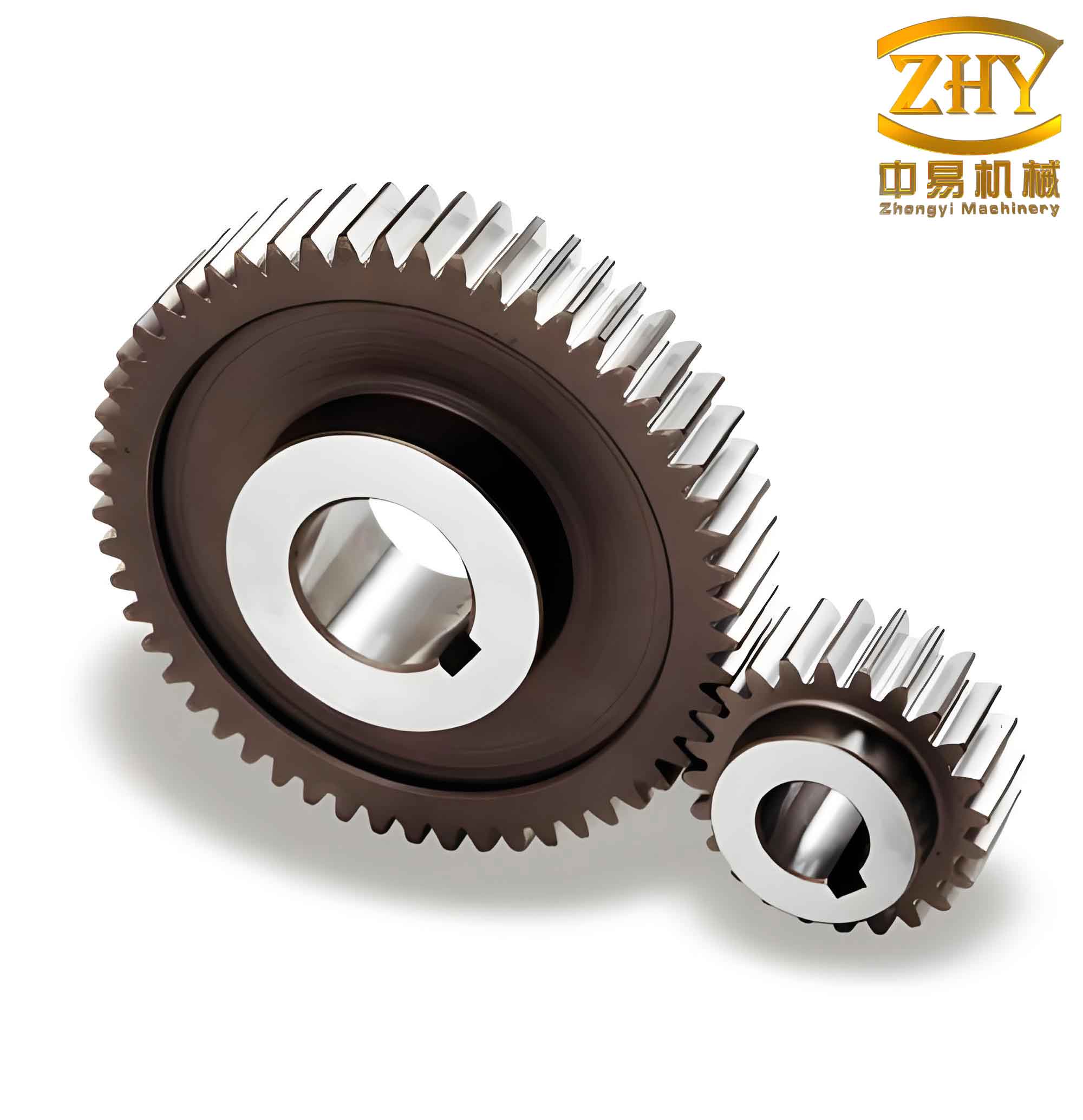
The gear material is assumed to be homogeneous and isotropic. The finite element mesh is generated using the SOLID95 element type, a 20-node hexahedral element that provides high accuracy for curved boundaries. The meshing process yields 21,535 nodes and 11,063 elements. The solid model and the finite element mesh are shown in Figure 1 (the actual image is inserted below). The boundary conditions are applied in accordance with the operating state: the inner bore surface is fully constrained (all degrees of freedom fixed) to simulate the rigid connection to the shaft. This condition reflects the actual installation where the gear is tightly mounted on the shaft and the bore cannot translate or rotate.
Due to the cyclic symmetry of the straight spur gear geometry, a sector model could be employed to reduce computational effort. However, in this study we adopt the full model to capture all possible mode shapes without any symmetry assumptions. The modal analysis is performed using the Block Lanczos method, which is efficient for extracting a large number of modes in systems with medium to large degrees of freedom. The first six natural frequencies are extracted and analyzed, as higher modes typically have less influence on the low-frequency vibration response.
Results of Modal Analysis
The natural frequencies of the first six modes are listed in Table 2. The corresponding mode shapes are described qualitatively. Note that for straight spur gears, the mode shapes often involve combinations of bending, torsion, and axial motions of the gear body.
| Mode order | Natural frequency (Hz) | Mode shape description |
|---|---|---|
| 1 | 1523.6 | First-order bending of the gear body in the plane of rotation |
| 2 | 1525.1 | First-order bending perpendicular to the plane of rotation |
| 3 | 2147.8 | Torsional mode about the gear axis |
| 4 | 2894.3 | Second-order bending with nodal diameters |
| 5 | 2901.7 | Asymmetric bending coupled with local tooth deformation |
| 6 | 3562.5 | Axial breathing mode with radial expansion/contraction |
The first two modes are nearly degenerate (very close frequencies) because the gear geometry is almost axisymmetric. The slight difference arises from the discrete tooth pattern. The torsional mode at 2147.8 Hz is particularly important because straight spur gears are often subjected to torque fluctuations from the meshing process. If the tooth meshing frequency (which equals the product of the rotational speed and number of teeth) coincides with this torsional natural frequency, severe torsional resonance may occur. The fourth and fifth modes involve more complex deformations of the gear rim and web. The sixth mode shows an axial breathing pattern where the gear expands and contracts radially while also moving axially.
Discussion and Engineering Implications
The modal analysis results provide valuable insights for the dynamic design of straight spur gears. To avoid resonance, the operating speed range should be selected such that the fundamental tooth meshing frequency and its harmonics are sufficiently far from the natural frequencies listed in Table 2. For instance, if the gear rotates at 1500 rpm, the meshing frequency is \(1500/60 \times 25 = 625\) Hz, which is well below the first natural frequency. However, if the gear is part of a variable-speed transmission, all possible speed ranges must be checked. In particular, the torsional mode (mode 3) is often the most critical because torque variations directly excite torsional vibrations. Design modifications such as increasing the face width, altering the web thickness, or adding damping treatments can shift the natural frequencies to safer ranges.
The finite element model used in this analysis assumes a fully constrained inner bore. In reality, the gear-shaft connection has finite stiffness, which would lower the natural frequencies slightly. Moreover, the presence of lubricant and supporting bearings introduces additional damping, which reduces the vibration amplitude even if resonance occurs. Nevertheless, the undamped modal analysis provides the fundamental frequency baseline that should not be exceeded by the excitation frequencies.
Another important aspect is the influence of gear geometry on mode shapes. The results show that the first six modes involve global deformations of the gear body rather than local tooth bending. This indicates that the gear web and rim stiffness dominate the low-frequency dynamics. For lightweight design, one should ensure that the rim and web are adequately stiff to avoid excessive deformation under dynamic loads.
Conclusion
In this work, we performed a finite element modal analysis of a standard straight spur gear using ANSYS. The three-dimensional solid model accurately represents the gear geometry, and the boundary conditions simulate the actual mounting. The first six natural frequencies and the corresponding mode shapes were obtained. The results show that the first two bending modes occur at approximately 1524 Hz, followed by a torsional mode at 2148 Hz and higher-order complex modes. These data serve as essential references for the dynamic design and optimization of straight spur gears. By ensuring that operating excitation frequencies avoid these natural frequencies, we can prevent resonance-induced failures and reduce noise. The methodology presented here can be extended to other gear geometries and boundary conditions, providing a reliable tool for gear dynamic analysis in engineering practice.