
In the field of precision transmission, particularly for industrial robots and CNC machine tools, the RV reducer has emerged as a critical component due to its compact size, high load capacity, large transmission ratio, and excellent efficiency. The need for efficient design and analysis of these reducers has led to the adoption of virtual prototyping technologies. In this article, I will present a comprehensive methodology for three-dimensional parametric modeling and virtual assembly of RV reducers, leveraging Pro/ENGINEER (Pro/E) as the primary platform. This approach aims to streamline the development process by creating adaptable digital models that can be used for finite element analysis (FEA) in ANSYS and dynamic simulation in ADAMS, thereby reducing reliance on physical prototypes and accelerating innovation cycles.
The RV reducer, often referred to as the 2K-V transmission in some regions, is an advanced evolution from cycloidal pin gear mechanisms. Its superior performance characteristics, including high rigidity, smooth operation, and precision, make it a focal point in robotics and automation. However, the diversity in specifications and models poses a significant challenge in design and testing. Traditional modeling for each variant is labor-intensive and time-consuming. To address this, I propose a feature-based parametric modeling strategy that capitalizes on the structural similarities across different RV reducer types. This method not only simplifies model creation but also ensures consistency in assembly relationships when parameters are altered. Throughout this discussion, the term ‘RV reducer’ will be emphasized to underscore its centrality in this work.
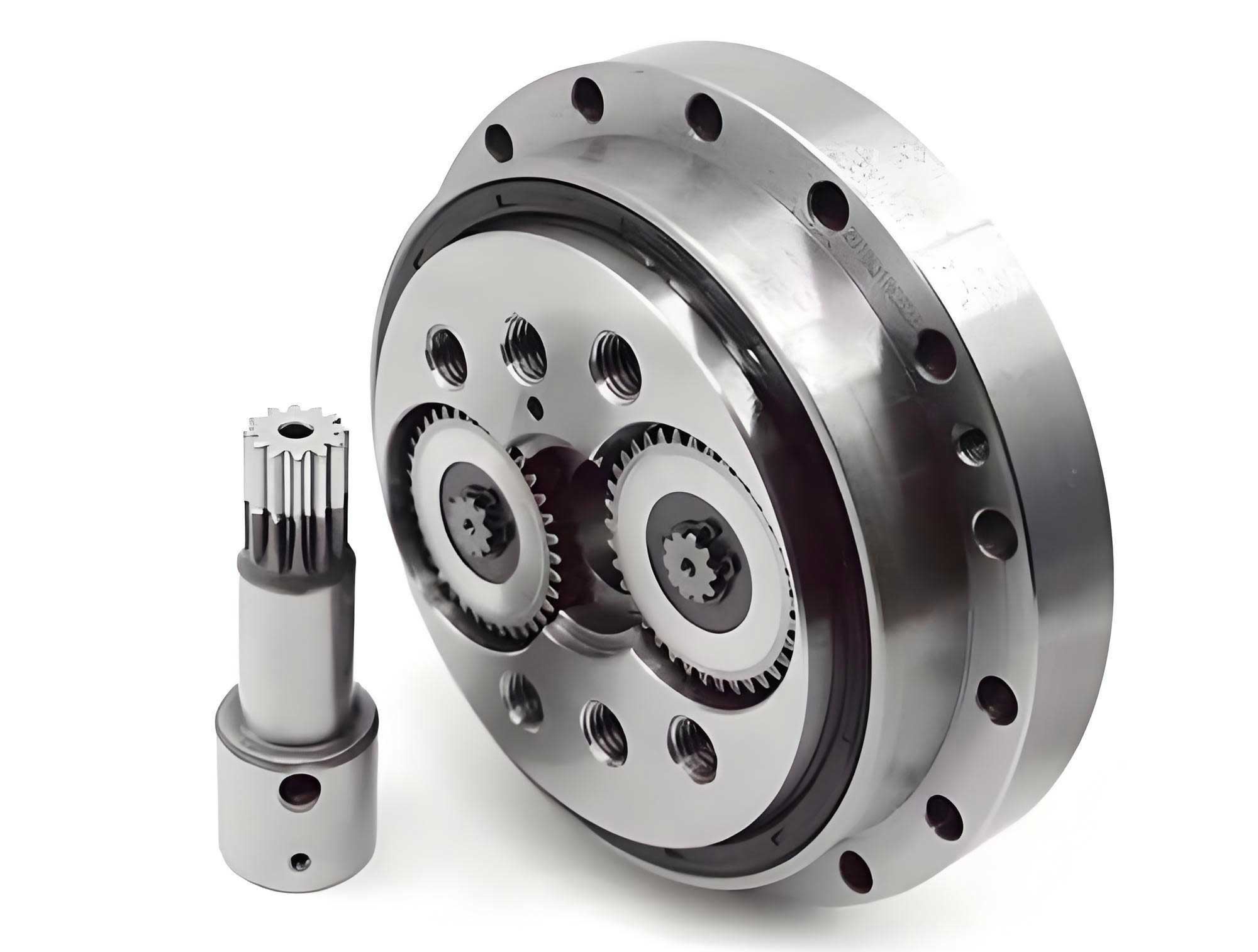
The foundation of this methodology lies in parametric design, which allows for automatic updates to the three-dimensional geometry based on defined parameters. This is particularly beneficial for RV reducers, where components like the cycloidal disk and involute gears have complex, mathematically defined profiles. By integrating these mathematical relationships directly into the CAD environment, we can generate accurate models that are easily modifiable. In the following sections, I will delve into the detailed steps for modeling each key component, the assembly process, validation techniques, and potential analyses enabled by this parametric framework. The goal is to provide a practical, user-friendly approach that enhances efficiency in both design and simulation phases for RV reducers.
Introduction to RV Reducers and Virtual Prototyping
The RV reducer is a two-stage transmission system that combines a planetary gear train with a cycloidal drive. Its operation involves an input shaft connected to an involute gear, which drives crankshafts that, in turn, engage with cycloidal disks. These disks interact with a stationary pin gear to produce a reduced output rotation. This intricate mechanism offers advantages such as high torque density and backlash minimization, making it indispensable in applications requiring precise motion control. The proliferation of RV reducer variants in the market necessitates a flexible design approach to cater to different performance requirements and sizes.
Virtual prototyping has revolutionized engineering design by enabling the creation of digital twins that mimic physical systems. Through tools like ANSYS for stress analysis and ADAMS for multi-body dynamics, engineers can predict behavior, optimize parameters, and identify issues before manufacturing. For RV reducers, this means assessing factors like load distribution, vibration, and efficiency in a cost-effective manner. However, the effectiveness of these simulations hinges on the accuracy and adaptability of the underlying three-dimensional models. Hence, parametric modeling becomes essential to avoid repetitive modeling tasks and to facilitate iterative design improvements. This article focuses on implementing such a system using Pro/E, chosen for its robust feature-based capabilities and widespread use in mechanical design.
Parametric Modeling of RV Reducer Components
The parametric modeling process begins with defining key features and their mathematical relationships. Each component of the RV reducer is modeled with parameters that control its dimensions and geometry. This ensures that any changes to these parameters automatically propagate through the model, updating all dependent features. I will start with the cycloidal disk, which is the heart of the RV reducer’s second stage, followed by the involute gears and other auxiliary parts. Tables and equations will be used extensively to summarize these parameters and relationships.
Cycloidal Disk Parametric Modeling
The cycloidal disk’s tooth profile is derived from the epitrochoidal curve, which depends on several geometric parameters. In Pro/E, this is achieved by creating a curve from an equation and then using it to generate the solid model. The critical parameters for the cycloidal disk are listed in Table 1, along with example values for an RV-40E reducer. These parameters define the shape and size of the teeth, influencing the performance of the RV reducer.
| Parameter | Example Value | Description |
|---|---|---|
| \(z_g\) | 39 | Number of teeth on cycloidal disk |
| \(z_b\) | 40 | Number of pins in the pin gear |
| \(r_z\) | 66 mm | Radius of pin center circle |
| \(r_{rz}\) | 3 mm | Radius of each pin |
| \(e\) | 1.5 mm | Eccentricity distance |
| \(m\) | 0 mm | Offset modification for profile shifting |
| \(n\) | 0 mm | Equidistant modification for profile shifting |
| \(k\) | Calculated | Shortening coefficient |
| \(a\) | Calculated | Rotation angle for curve generation |
To establish the parametric relationships, I define the following equations in Pro/E’s relation editor. These equations compute the shortening coefficient \(k\) and the base angle \(a\) based on the input parameters:
$$ k = \frac{e \cdot z_b}{(r_z + m) / (z_b – z_g)} $$
$$ a = \frac{180}{z_g} $$
The cycloidal curve is then generated using a Cartesian coordinate system with the parameter \(t\) ranging from 0 to 1. The parametric equations for the curve are:
$$ \text{ang} = a \cdot t $$
$$ p = \frac{k \cdot \sin(z_b \cdot \text{ang}) – \sin(\text{ang})}{\sqrt{1 + k^2 – 2k \cdot \cos(z_g \cdot \text{ang})}} $$
$$ q = \frac{-k \cdot \cos(z_b \cdot \text{ang}) + \cos(\text{ang})}{\sqrt{1 + k^2 – 2k \cdot \cos(z_g \cdot \text{ang})}} $$
$$ x = (r_z + m) \cdot \sin(\text{ang}) – e \cdot \sin(z_b \cdot \text{ang}) + (r_{rz} + n) \cdot p $$
$$ y = (r_z + m) \cdot \cos(\text{ang}) – e \cdot \cos(z_b \cdot \text{ang}) – (r_{rz} + n) \cdot q $$
$$ z = 0 $$
By inputting these equations into Pro/E’s curve-from-equation tool, I create half of a tooth profile. Mirroring this curve across a reference plane yields a full tooth, which is then patterned circularly with an angle of \(360/z_g\) degrees and \(z_g\) instances. This patterning is also parameterized by linking the angle and number of instances to the parameters via relations. Finally, extruding the profile to a specified thickness (e.g., 10 mm) and adding features like bearing holes results in the three-dimensional cycloidal disk model. Altering any parameter in Table 1 instantly updates the entire geometry, demonstrating the power of parametric design for RV reducers.
Involute Gear Parametric Modeling
The first stage of the RV reducer involves involute gears that transmit motion from the input shaft to the crankshafts. Modeling these gears parametrically requires defining standard gear parameters and their interrelations. Table 2 outlines the key parameters for an example involute gear used in an RV reducer.
| Parameter | Example Value | Description |
|---|---|---|
| \(m\) | 1.5 mm | Module |
| \(z\) | 32 | Number of teeth |
| \(\alpha\) | 20° | Pressure angle |
| \(h_{ax}\) | 1 | Addendum coefficient |
| \(c_x\) | 0.25 | Dedendum coefficient |
| \(b\) | 7 mm | Gear width |
| \(x\) | 0 | Profile shift coefficient |
| \(h_a\) | Calculated | Addendum height |
| \(h_f\) | Calculated | Dedendum height |
| \(d\) | Calculated | Pitch diameter |
| \(d_a\) | Calculated | Tip diameter |
| \(d_f\) | Calculated | Root diameter |
| \(d_b\) | Calculated | Base diameter |
The following relations are established in Pro/E to compute the derived dimensions automatically:
$$ h_a = (h_{ax} + x) \cdot m $$
$$ h_f = (h_{ax} + c_x – x) \cdot m $$
$$ d = m \cdot z $$
$$ d_a = d + 2 \cdot h_a $$
$$ d_b = d \cdot \cos(\alpha) $$
$$ d_f = d – 2 \cdot h_f $$
To create the gear profile, I sketch four concentric circles representing the tip, pitch, root, and base circles on a reference plane. Their diameters are linked to the calculated parameters: \(d_1 = d\), \(d_2 = d_a\), \(d_3 = d_f\), \(d_4 = d_b\). The involute curve is generated using parametric equations in a Cartesian system:
$$ \text{ang} = 90 \cdot t $$
$$ r = \frac{d_b}{2} $$
$$ s = \frac{\pi \cdot r \cdot t}{2} $$
$$ x_c = r \cdot \cos(\text{ang}) $$
$$ y_c = r \cdot \sin(\text{ang}) $$
$$ x = x_c + s \cdot \sin(\text{ang}) $$
$$ y = y_c – s \cdot \cos(\text{ang}) $$
$$ z = 0 $$
This curve is trimmed and mirrored to form a single tooth profile, with fillets added at the root. The fillet radius \(r_f\) is determined conditionally based on the addendum coefficient:
$$ \text{If } h_{ax} \geq 1: \quad r_f = 0.38 \cdot m $$
$$ \text{If } h_{ax} < 1: \quad r_f = 0.46 \cdot m $$
After extruding the profile to the gear width \(b\), the tooth is patterned circularly with an angle of \(360/z\) degrees and \(z\) instances. This creates a fully parametric involute gear model that updates seamlessly with parameter changes, essential for adapting the RV reducer to different specifications.
Parametric Modeling of Other Components
Additional parts of the RV reducer, such as the crankshafts, output plate, support disk, and housing, are modeled using simpler extrusion and revolution features. To maintain consistency, all sketches are created on standard reference planes (e.g., FRONT for extrusions, TOP for revolutions), ensuring that the Z-axis orientation aligns across components for easier assembly. Key dimensions, like diameters and lengths, are parameterized and added to relations. For instance, the crankshaft eccentricity is tied to the parameter \(e\) from the cycloidal disk, preserving design intent. To simplify subsequent analyses in ANSYS or ADAMS, non-critical features like chamfers and bolt holes may be omitted, and connections like splines can be represented as solid cylinders. This reduces computational load without sacrificing the functional integrity of the RV reducer model.
Virtual Assembly of the RV Reducer
The assembly process in Pro/E leverages parent-child relationships to ensure that changes in part parameters do not disrupt the overall assembly constraints. This is crucial for maintaining the functionality of the RV reducer across different configurations. I begin by creating a sub-assembly for the pins, which are arrayed circularly within the pin gear housing. This sub-assembly is then imported into the main assembly as a fixed component (default constraint). Following this, the major moving parts are added in a sequence that reflects their kinematic dependencies: output plate, crankshafts, cycloidal disks, involute gears, and input shaft.
To enable motion simulation, revolute joints (pin constraints) are applied to rotating components. The output plate is fixed in translation but free to rotate, serving as the foundation. Crankshafts are attached to the output plate with pin constraints, establishing them as children of the output plate. Cycloidal disks and involute gears are then assembled to the crankshafts, making the crankshafts their parents. This hierarchy ensures that when crankshaft parameters change, the dependent parts update accordingly. For gear meshing alignment, reference planes are created on the involute gear and input shaft gear to initially align tooth profiles, then removed to allow motion definition. Constraints like “mate” and “align” are used to position parts accurately, resulting in a fully constrained assembly of the core RV reducer mechanism.
Secondary components, such as support disks, bearings, and the pin gear housing, are added last. Their assembly constraints are tied to primary parts: for example, support disks and main bearings reference the output plate, while crankpin bearings reference the crankshafts. The pin gear housing is parented to the pin sub-assembly. This structured approach guarantees that parameter modifications propagate through the entire assembly without breaking constraints. The final assembled RV reducer model is a cohesive digital prototype ready for validation and analysis.
Validation of the Parametric Model
To verify the correctness of the parametric RV reducer model, I perform an interference check and motion simulation within Pro/E. The interference analysis confirms no geometric clashes between components, ensuring a feasible design. For motion simulation, I define gear pairs to replicate the transmission behavior. The first-stage gear pair between the input shaft and involute gear has a ratio based on tooth counts (e.g., 16:32 for the example). The second-stage motion, involving the cycloidal disk and pins, is modeled as a hypothetical gear pair to represent the speed reduction. The relationship between the cycloidal disk’s revolution and rotation is given by:
$$ \text{Speed ratio} = \frac{z_b}{z_b – z_g} $$
For the example with \(z_b = 40\) and \(z_g = 39\), the ratio is 40:1. A servo motor is applied to the input shaft with a speed of 1500 RPM. Running a kinematic analysis produces smooth motion, and measuring the output plate speed yields approximately 18.52 RPM, which matches the theoretical value:
$$ \text{Output speed} = \frac{1500}{81} \approx 18.52 \text{ RPM} $$
This agreement between simulation and theory validates the parametric model’s accuracy. The animation also visually confirms proper engagement of gears and cycloidal teeth, reinforcing the reliability of this modeling approach for RV reducers.
Parametric Analysis for RV Reducer Performance
With a validated parametric model, various analyses can be conducted to evaluate the RV reducer’s performance under different conditions. These studies leverage the adaptability of the model to explore design trade-offs and optimization opportunities.
Pure Kinematic Analysis
Kinematic analysis focuses on motion without considering forces or masses. Using the constraints defined in the assembly, I can visualize the relative movements of all components and calculate velocity and acceleration profiles. This is useful for verifying the transmission logic and identifying potential dead points or irregularities in motion. For the RV reducer, kinematic simulation confirms that the cycloidal disk undergoes a compound motion of rotation and revolution, leading to the desired speed reduction. By adjusting parameters like tooth counts or eccentricity, I can observe how these changes affect motion paths and output characteristics, providing insights for initial design sizing.
Dynamic Analysis
Dynamic analysis incorporates mass properties, materials, and contact forces to simulate real-world behavior. I assign material properties (e.g., steel for gears, aluminum for housings) to all parts and define contact pairs between mating surfaces. This allows for the investigation of load distribution, vibration, and efficiency. For instance, by modeling only the first-stage gear contact as dynamic while keeping the second stage kinematic, I can isolate the impact of involute gear meshing forces on the RV reducer’s output stability. Similarly, focusing on the cycloidal-pin contact reveals how tooth engagement dynamics influence torque ripple and backlash. Coupling both stages provides a comprehensive view of system dynamics, enabling the assessment of resonance frequencies and stress concentrations under operational loads.
Clearance and Tolerance Analysis
Clearances play a critical role in the performance of RV reducers, affecting backlash, noise, and wear. Using the parametric model, I can modify dimensions to simulate different clearance conditions. For example, by adjusting the profile shift parameters \(m\) and \(n\) for the cycloidal disk, I can study how modifications influence the meshing gap between the disk and pins. This is expressed through updated equations in the cycloidal profile:
$$ x = (r_z + m) \cdot \sin(\text{ang}) – e \cdot \sin(z_b \cdot \text{ang}) + (r_{rz} + n) \cdot p $$
$$ y = (r_z + m) \cdot \cos(\text{ang}) – e \cdot \cos(z_b \cdot \text{ang}) – (r_{rz} + n) \cdot q $$
Varying \(m\) and \(n\) alters the tooth shape, which in turn affects the clearance. Dynamic simulations with these modified models can quantify the impact on output precision and longevity. Similarly, tolerances for bearing fits or gear alignments can be parameterized to analyze assembly stack-up effects. This capability makes the parametric RV reducer model a powerful tool for sensitivity analysis and robust design.
Conclusion
In this article, I have presented a detailed methodology for three-dimensional parametric modeling and virtual assembly of RV reducers using Pro/ENGINEER. By leveraging feature-based design and mathematical relationships, I created adaptable models for key components like the cycloidal disk and involute gears, ensuring that changes in parameters automatically update the geometry. The assembly process, structured around parent-child relationships, maintains constraint integrity across variations, streamlining the design process. Validation through motion simulation confirmed the model’s accuracy, with output speeds matching theoretical calculations. Furthermore, I outlined how this parametric framework enables comprehensive analyses—including kinematic, dynamic, and clearance studies—to optimize RV reducer performance without physical prototyping.
The advantages of this approach are manifold: it reduces repetitive modeling efforts, accelerates design iterations, and enhances the efficiency of subsequent FEA and multibody simulations. The simplicity and practicality of the method make it accessible to engineers and researchers working on RV reducers. As the demand for high-precision transmission systems grows, such parametric modeling techniques will become increasingly vital in developing innovative, reliable, and cost-effective RV reducer solutions. Future work could extend this framework to include automated optimization routines or integration with cloud-based design platforms, further advancing the state of RV reducer technology.