
In the field of precision machinery, such as industrial robots and CNC machine tools, RV reducers play a critical role due to their compact size, high transmission ratio, longevity, and accuracy. One of the key performance indicators for RV reducers is geometric backlash, which refers to the angular hysteresis of the output shaft when the input shaft reverses direction, solely caused by geometric inaccuracies in transmission components like dimensions, shapes, and positions. Understanding and modeling this backlash is essential for enhancing transmission precision and guiding tolerance design in manufacturing. In this paper, I focus on developing an accurate geometric backlash model for RV reducers, incorporating both the magnitude and direction of manufacturing and installation errors, which are often overlooked in prior studies. By considering factors such as cycloidal gear tooth profile modification methods and error orientations, I aim to provide a comprehensive analysis that reflects real-world variability in backlash across different output shaft phases.
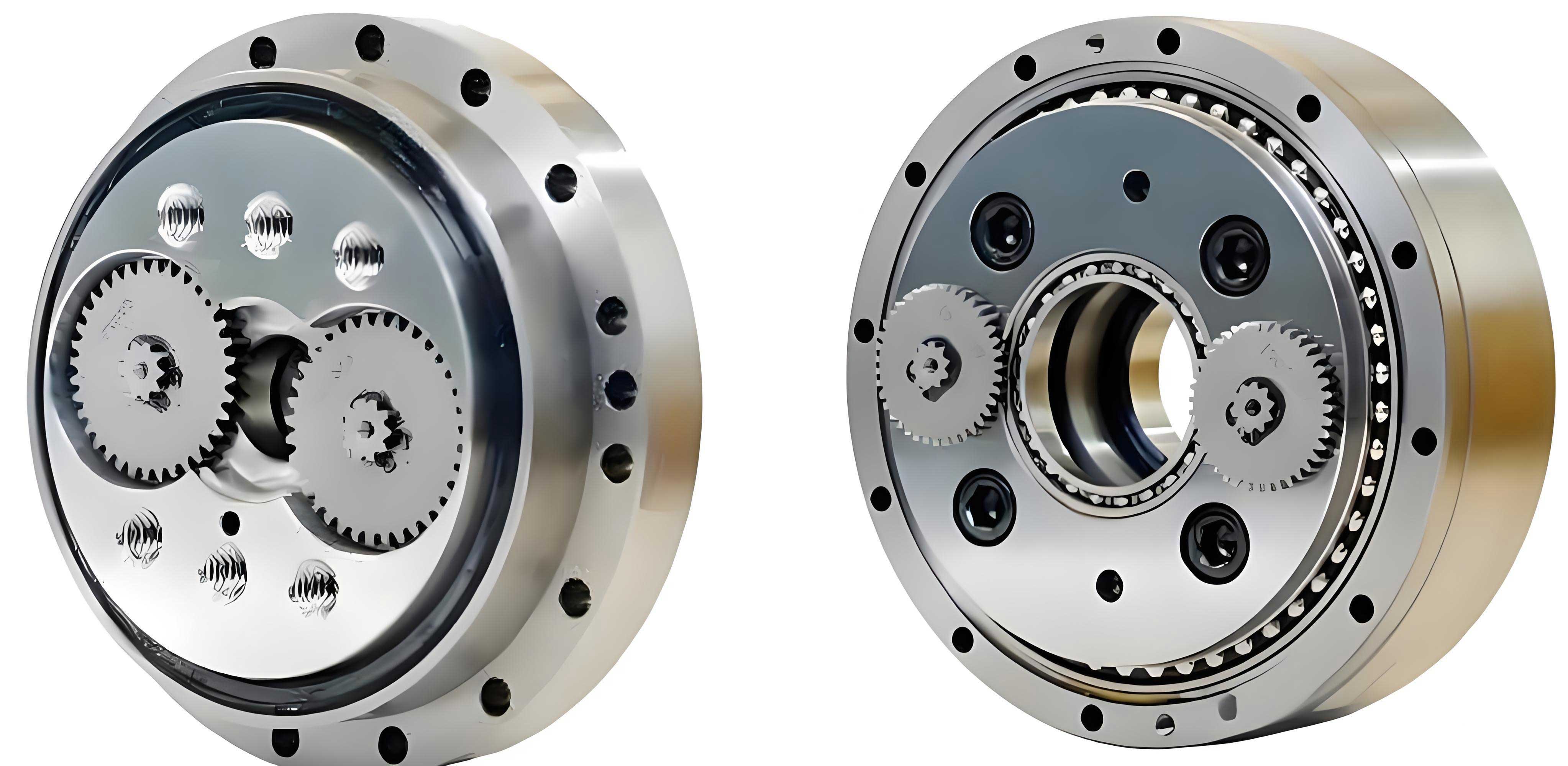
The RV reducer consists of two main stages: a involute cylindrical gear reduction mechanism and a cycloidal pin-wheel planetary transmission mechanism. The geometric model for backlash analysis involves multiple coordinate systems to represent the positions and movements of components like the sun gear, planetary gears, crankshafts, cycloidal gears, and pin teeth. Establishing this model is the foundation for deriving mathematical expressions that quantify backlash contributions from various error sources.
To set up the geometric model, I define a static coordinate system (x, y) with its origin at the center of the pin wheel, O. For the sun gear, I attach a moving coordinate system (x_s, y_s) at its center, O_s. Similarly, for each planetary gear, I use a moving coordinate system (x_pi, y_pi) centered at O_pi, where i = 1, 2, 3. For the cycloidal gears, indexed as j = 1, 2, I establish moving coordinate systems (x_j, y_j) at their theoretical centers, O_j, with the x_j-axis aligned along the eccentric direction. Initially, all x-axes are aligned with the static x-axis. This coordinate framework allows me to trace the interactions and errors across the RV reducer’s components during operation.
The mathematical model for geometric backlash in RV reducers is derived by analyzing error contributions from both the involute gear stage and the cycloidal gear stage. Each error source, such as center distance errors, tooth profile modifications, and radial runouts, is expressed in terms of its impact on the angular hysteresis of the output shaft. I use formulas to calculate the backlash in arc minutes, considering the reducer’s transmission ratio and geometric parameters.
Mathematical Model for Involute Gear Stage Backlash
The involute gear stage, which includes the sun gear and planetary gears, contributes to backlash through several error factors. These include center distance errors due to installation inaccuracies, gear tooth flank clearances for manufacturing tolerances and lubrication, and radial runout errors from gear eccentricities. I derive equations for each case, incorporating error magnitudes and directions.
For the sun gear center installation error, denoted as (E_sz, β_sz), where E_sz is the magnitude and β_sz is the direction angle, the actual center distance between the sun gear and the i-th planetary gear during rotation is given by:
$$ L_i = \sqrt{L^2 + E_{sz}^2 – 2L \cdot E_{sz} \cos(\beta_{sz} – \theta_c – \phi_i)} $$
Here, L is the theoretical center distance, θ_c is the rotation angle of the planet carrier (output shaft), and φ_i = 2π(i-1)/3 represents the angular position of the crankshaft holes on the cycloidal gear or planet carrier. The resulting circumferential backlash j_wti due to this error is calculated using gear geometry formulas:
$$ j_{bti} = e_{b2} – s_{b1} + 2(r_{b1} + r_{b2}) \text{inv} \alpha_{wti} $$
$$ \cos \alpha_{wti} = \frac{r_{b1} + r_{b2}}{L_i} $$
$$ j_{wti} = \frac{j_{bti}}{\cos \alpha_{wti}} $$
where r_b1 and r_b2 are the base circle radii of the sun gear and planetary gear, respectively, α is the pressure angle, and inv denotes the involute function. The backlash in terms of output shaft rotation is:
$$ \Delta \phi_{wti} = \frac{180 \times 60}{N \pi r_1} j_{wti} $$
with N as the total transmission ratio of the RV reducer and r_1 as the pitch radius of the sun gear. This formulation shows how error direction β_sz influences the phase of backlash variation over output shaft rotation.
Similarly, for planetary gear center installation errors (E_pzi, β_pzi), the center distance becomes:
$$ L_i = \sqrt{L^2 + E_{pzi}^2 + 2L E_{pzi} \cos(\beta_{pzi} – \phi_i)} $$
leading to a backlash contribution Δφ_wpi. Other errors, such as gear tooth flank clearance j_ct, sun gear radial runout (E_st, β_st), and planetary gear radial runout (E_pti, β_pti), are modeled with analogous equations. For instance, the sun gear radial runout affects center distance as:
$$ L_{sti} = \sqrt{L^2 + E_{st}^2 – 2L \cdot E_{st} \cos[(\beta_{st} + \theta_s – \theta_c) – \phi_i]} $$
where θ_s is the sun gear rotation angle. These errors collectively contribute to the overall backlash in the involute stage, with each having a directional component that modulates the backlash phase.
Mathematical Model for Cycloidal Gear Stage Backlash
The cycloidal gear stage, involving cycloidal gears and pin teeth, is a major source of backlash in RV reducers due to its position at the output end. Error factors here include pin tooth slot center circle radius deviations, circumferential position errors, pin radius errors, cycloidal gear tooth profile modifications, and manufacturing inaccuracies from grinding processes. I derive backlash expressions for each, considering the kinematics of cycloidal motion.
For a pin tooth slot center circle radius deviation R_k, the clearance between the k-th pin tooth and the cycloidal gear tooth is:
$$ e_{Rk} = R_k \cos(\alpha_{jk} – \phi_{jk}) $$
where α_jk is the angle between the line connecting the k-th pin center and the j-th cycloidal gear’s node and the x_j-axis, and φ_jk is the angle of the pin radius direction relative to x_j. The resulting backlash on the output shaft is:
$$ \Delta \phi_{Rk} = \frac{e_{Rk_{min1}}}{a z_c} + \frac{e_{Rk_{min2}}}{a z_c} $$
Here, a is the eccentricity of the crankshaft, z_c is the number of cycloidal gear teeth, and e_Rk_min1 and e_Rk_min2 represent the minimum clearances during forward and reverse rotations of the cycloidal gear, respectively. This accounts for the bidirectional nature of backlash in RV reducers.
Other errors, such as pin tooth slot circumferential position deviation P_k, pin radius error G_k, and cycloidal gear tooth profile modification X_k, are modeled similarly. For example, the clearance due to profile modification is:
$$ \Delta \phi_{Xk} = \frac{X_{k_{min1}}}{a z_c} + \frac{X_{k_{min2}}}{a z_c} $$
Manufacturing errors from grinding, like feed depth error S_k and indexing error F_k, also contribute. The clearance from feed depth error is:
$$ e_{Sk} = S_k \cos(\alpha_{jk} – \phi_{Sjk}) $$
where φ_Sjk is the angle between the pin center-cycloidal gear center line and the x_j-axis. Radial runout errors of cycloidal gears (E_btj, β_btj) and eccentricity errors in crankshaft holes (E_hji, β_hji) introduce clearances that vary with output shaft angle θ_c:
$$ e_{btjk} = -E_{btj} \cos[\phi_{Sjk} – (\beta_{btj} + \theta_c)] \cos(\alpha_{jk} – \phi_{Sjk}) $$
These equations highlight how error directions influence backlash phase, making the backlash value dependent on the output shaft position in RV reducers.
Backlash from Crankshaft and Planet Carrier Errors
Errors in crankshaft eccentric cams and planet carrier assembly further add to backlash. For crankshaft eccentric cam errors (E_cj, β_cj), the clearance is:
$$ e_{cjk} = -E_{cj} \cos[\phi_{Sjk} – (\beta_{cj} + \theta_p)] \cos(\alpha_{jk} – \phi_{Sjk}) $$
where θ_p is the planetary gear rotation angle. Similarly, planet carrier crankshaft hole eccentricity (E_a, β_a) and assembly errors (E_c, β_c) are modeled with the same form. Additionally, bearing clearance u in the crankshaft holes contributes to backlash; the angular shift required to eliminate this clearance is:
$$ \Delta \theta_{pi} = \frac{180 \times u}{\pi a} $$
which translates to an output shaft backlash of:
$$ \Delta \phi_{qi} = 2 \times \Delta \theta_{ci} \quad \text{with} \quad \Delta \theta_{ci} = \frac{(1 – N) \Delta \theta_{pi}}{z_s / z_p + N – 1} $$
where z_s and z_p are tooth numbers of sun and planetary gears. This comprehensive model integrates all error sources, emphasizing their directional effects on backlash in RV reducers.
Simulation of Backlash in RV Reducers
To validate the mathematical model, I perform simulations using typical RV reducer parameters and error tolerances. The parameters for a sample RV reducer are listed in Table 1, and manufacturing/installation errors with their ranges and directional variability are summarized in Table 2. These tables help quantify the impact of each error on overall backlash.
| Parameter Name | Value |
|---|---|
| Pin tooth center circle diameter d_p (mm) | 229 |
| Pin tooth diameter d_rp (mm) | 10 |
| Eccentricity a (mm) | 2.2 |
| Number of cycloidal gear teeth z_c | 39 |
| Cycloidal gear width (mm) | 18 |
| Sun gear tooth number z_1 | 21 |
| Planetary gear tooth number z_2 | 42 |
| Center distance of involute gears (mm) | 63 |
| Module m (mm) | 2 |
| Pressure angle α (°) | 20 |
| Transmission ratio N | 81 |
| Error Factor | Error (μm) | Direction Range (°) |
|---|---|---|
| Sun gear center installation error (E_sz, β_sz) | 17 | 0–360 |
| Planetary gear center installation error (E_pzi, β_pzi) | 17 | 0–360 |
| Gear tooth flank clearance j_ct | 11 | — |
| Sun gear radial runout error (E_st, β_st) | 21 | 0–360 |
| Planetary gear radial runout error (E_pti, β_pti) | 21 | 0–360 |
| Pin tooth slot center circle radius deviation R_k | 5 | — |
| Pin tooth slot circumferential position deviation P_k | ±5 | — |
| Pin tooth slot radius error C_k | 0–15 | — |
| Pin tooth radius error G_k | 0 to -4 | — |
| Cycloidal gear tooth profile modification error X_k | ±4 | — |
| Grinding feed depth error S_k | ±5 | — |
| Indexing error F_k | ±5 | — |
| Cycloidal gear radial runout error (E_btj, β_btj) | 6 | 0–360 |
| Cycloidal gear crankshaft hole eccentricity error (E_hji, β_hji) | 3 | 0–360 |
| Crankshaft eccentric cam error (E_cji, β_cji) | 3 | 0–360 |
| Bearing clearance u (μm) | 2 | — |
| Planet carrier crankshaft hole eccentricity error (E_ai, β_ai) | 3 | 0–360 |
| Planet carrier assembly error (E_c, β_c) | 3 | 0–360 |
Using these parameters, I simulate backlash contributions from individual errors and their combinations. For instance, with a sun gear center installation error of E_sz = 8 μm and directions β_sz = 0°, 70°, and 140°, the backlash Δφ_wti varies with output shaft angle, as shown in Figure 1 (simulated data). The backlash curves exhibit periodic peaks every 120° due to the three planetary gears in the RV reducer. The error direction shifts the phase of backlash variation but does not alter its amplitude, indicating that directional effects modulate timing rather than magnitude in this context.
For the sun gear radial runout error with E_st = 11 μm and directions β_st = 0°, 70°, and 140°, the backlash Δφ_sti shows high-frequency fluctuations over a small output rotation range (e.g., 9°), as the sun gear engages multiple teeth rapidly. Again, direction affects phase but not amplitude. In contrast, errors in the cycloidal stage, such as pin tooth slot center circle radius deviation R_k = 3 μm, produce larger backlash values due to the higher transmission ratio at the output, with periodic variations across output shaft angles.
When considering cycloidal gear radial runout errors (E_bt = 6 μm, β_bt = 0°, 70°, 140°), the backlash Δφ_btk similarly depends on direction for phase shift. To assess overall backlash, I combine all errors using mean tolerance values and random directions, along with a cycloidal gear tooth profile modification method that combines equidistant and offset modifications (e.g., -0.026 mm equidistant and -0.03 mm offset). The total backlash of the RV reducer, plotted against output shaft angle, reveals a periodic pattern with a minimum value of -0.691 arc minutes and a peak-to-peak difference of 0.046 arc minutes. If all error directions are set to zero degrees, the backlash becomes more pronounced, with a minimum of -0.875 arc minutes and a peak-to-peak difference of 0.16 arc minutes. This demonstrates that error directions can significantly influence both the absolute backlash and its variability in RV reducers, emphasizing the need for precise control in manufacturing and assembly.
Experimental Study on Backlash in RV Reducers
To validate the simulation results, I conduct experimental measurements of backlash on actual RV reducers. The test setup involves a servo motor-driven platform with a high-precision rotary encoder attached to the output shaft, allowing accurate angle measurement. The RV reducer used is a BX320 model with a transmission ratio of 201 and a rated torque of 3150 Nm, typical for industrial applications.
The backlash measurement method involves rotating the input shaft via the servo motor to specific output shaft angles, then reversing the motor direction and recording the angular lag of the output shaft. This process is repeated at multiple output shaft positions to capture backlash variation over a full rotation. I test two RV reducers of the same model and compile the backlash data in Table 3, which shows backlash values at 30° intervals of output shaft rotation.
| Output Shaft Angle (°) | Reducer 1 Backlash (arc min) | Reducer 2 Backlash (arc min) |
|---|---|---|
| 0 | 0.605 | 0.724 |
| 30 | 0.610 | 0.716 |
| 60 | 0.583 | 0.744 |
| 90 | 0.576 | 0.763 |
| 120 | 0.593 | 0.749 |
| 150 | 0.587 | 0.751 |
| 180 | 0.570 | 0.738 |
| 210 | 0.581 | 0.723 |
| 240 | 0.577 | 0.712 |
| 270 | 0.566 | 0.736 |
| 300 | 0.584 | 0.761 |
| 330 | 0.603 | 0.754 |
The data indicate that backlash varies with output shaft angle for both RV reducers, confirming the periodic nature predicted by the model. For Reducer 1, the maximum backlash is 0.610 arc minutes, the minimum is 0.566 arc minutes, and the peak-to-peak difference is 0.044 arc minutes. For Reducer 2, the values are 0.763 arc minutes maximum, 0.712 arc minutes minimum, and a 0.051 arc minutes peak-to-peak difference. These experimental peak-to-peak differences align closely with the simulation results (e.g., 0.046 arc minutes), validating the accuracy of the backlash model. The variations between reducers highlight manufacturing tolerances and error direction effects in real-world RV reducers.
Discussion and Implications
The findings from this study underscore the importance of considering both magnitude and direction of errors in backlash analysis for RV reducers. Traditional models that ignore error directions may overestimate or underestimate backlash, particularly in precision applications where even small angular hysteresis can affect performance. By incorporating directional effects, the model provides a more realistic representation of backlash variability across output shaft positions.
For the involute gear stage, errors like center installation and radial runout contribute minor backlash due to the high transmission ratio, but their directional phases add complexity. In the cycloidal gear stage, errors such as tooth profile modifications and pin tooth deviations have larger impacts, and their directions can be optimized through selective assembly or tolerance design. For instance, matching error directions to minimize peak-to-peak backlash could enhance the precision of RV reducers in robotics.
The simulation and experimental results also reveal that backlash is not constant but periodic, with cycles corresponding to the number of planetary gears or pin teeth. This periodicity must be accounted for in applications requiring high positional accuracy. Furthermore, the choice of cycloidal gear tooth profile modification method significantly influences backlash; methods like equidistant and offset modifications can be tuned to balance load distribution and minimize hysteresis.
Conclusion
In this paper, I have developed an accurate geometric backlash model for RV reducers that comprehensively accounts for manufacturing and installation errors, including their magnitudes and directions. The mathematical formulations cover both involute and cycloidal gear stages, deriving backlash contributions from various error sources. Simulations using typical parameters demonstrate that error directions affect the phase of backlash variation, and when combined with random directions, the overall backlash shows periodic behavior with manageable peak-to-peak differences. Experimental measurements on actual RV reducers confirm the model’s validity, showing similar periodic backlash patterns and variability.
This research provides a foundation for improving the transmission precision of RV reducers by guiding tolerance design and assembly processes. By understanding how errors interact directionally, manufacturers can implement strategies such as error compensation or selective component matching to reduce backlash. Future work could explore dynamic effects or thermal influences on backlash, but the current model offers a robust tool for enhancing the performance of RV reducers in high-precision mechanical systems.