
In the design and operation of high-power transmission systems, managing the thermal load generated by gear meshing is a critical engineering challenge. For high-speed spur gears, which are fundamental components in many industrial and marine applications, excessive temperatures can lead to reduced lubrication efficiency, accelerated wear, scuffing, and ultimately, catastrophic failure. While oil jet lubrication is a standard and effective method for cooling and lubricating these gears, accurately predicting the convective heat transfer coefficient (CHTC) on the tooth surface remains complex. This coefficient is paramount for precise thermal and thermo-elastohydrodynamic analyses, yet it is highly dependent on operational and lubrication parameters. This article delves into a detailed theoretical and simulation-based investigation of convective heat transfer on the tooth flanks of high-speed spur gears under jet lubrication conditions. The focus is on elucidating the influence of key parameters, namely jet velocity and nozzle-to-tooth distance, to provide deeper insights for thermal management design.
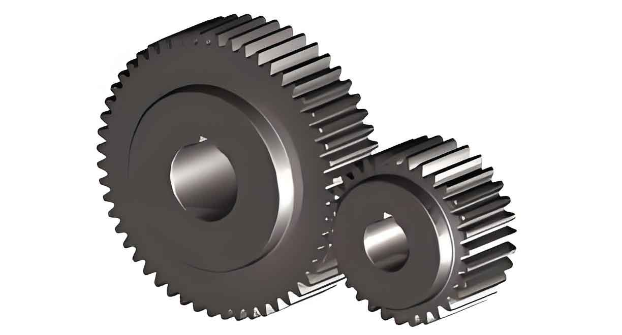
The primary mechanism of heat generation in meshing spur gears is sliding friction between the contacting tooth flanks. Although other sources like rolling friction and deformation losses exist, their contribution to the total heat flux is often considered secondary for preliminary thermal analysis. Therefore, the frictional heat generation power per unit area, $q$, on the tooth surface of spur gears can be estimated using the following fundamental relation:
$$ q = \mu \cdot p \cdot V_r $$
where $\mu$ is the coefficient of sliding friction, $p$ is the contact pressure (in N/m²) at the meshing point, and $V_r$ is the relative sliding velocity (in m/s) between the two spur gear teeth. The contact pressure for spur gears is typically calculated using Hertzian contact theory, while the sliding velocity varies along the path of contact, being zero at the pitch point and maximum at the beginning and end of engagement. Accurate determination of these variables is essential for establishing a realistic thermal boundary condition.
Once the heat generation is quantified, the next step is to model its dissipation. A significant portion of this heat is carried away by the lubricating oil via forced convection. For spur gears, a widely referenced semi-empirical correlation for the convective heat transfer coefficient between the gear tooth surface and the lubricating oil is given by Townsend et al.:
$$ h_t = 0.228 \cdot \text{Re}^{0.731} \cdot \text{Pr}^{0.333} \cdot \frac{K_o}{L} $$
Here, $h_t$ is the tooth surface convective heat transfer coefficient (W/m²·K), $K_o$ is the thermal conductivity of the lubricant (W/m·K), and $L$ is a characteristic length, often taken as the pitch diameter of the spur gear (m). The Reynolds number ($\text{Re}$) and Prandtl number ($\text{Pr}$) are defined as:
$$ \text{Re} = \frac{V \cdot h_m}{ u_f} $$
$$ \text{Pr} = \frac{\rho_f \cdot c_f \cdot u_f}{K_o} $$
where $V$ is the pitch line velocity (m/s), $h_m$ is the mean tooth height (m), $ u_f$ is the kinematic viscosity of the oil (m²/s), $\rho_f$ is the oil density (kg/m³), and $c_f$ is the specific heat capacity of the oil (J/kg·K). This formula provides a useful benchmark but inherently averages local effects influenced by the specific dynamics of oil jet impingement and flow over the complex geometry of spur gears.
To capture these localized effects, Computational Fluid Dynamics (CFD) simulation offers a powerful tool. The actual process of oil jet impinging on meshing spur gears involves a highly transient, multiphase (oil-air), and three-dimensional flow with splashing and film formation. For a focused parametric study on the impact of jet conditions, a significant yet justified simplification is employed. Observations indicate that the primary cooling effect occurs on the tooth flank directly facing the jet (e.g., the driving flank of the driving spur gear) and the rear flank of the adjacent driven spur gear. Therefore, the analysis can be reduced to studying the impingement of a single oil jet on a representative surface area equivalent to these two flanks. The nozzle is positioned above this surface, with the jet directed perpendicularly onto it. The surrounding domain is treated as open to atmosphere to allow for oil splash and air entrainment. The boundary conditions for this CFD model are set as follows: a velocity inlet at the nozzle exit, an opening condition at the domain sides, and a constant heat flux wall condition on the target surface representing the frictional heat generated by the spur gears.
The base parameters for the spur gear pair under consideration are summarized in Table 1. The lubricant is assumed to be a standard ISO VG 320 oil with corresponding properties at an operating temperature.
| Parameter | Pinion (O1) | Gear (O2) |
|---|---|---|
| Module (mm) | 8.8 | 59 |
| Number of Teeth | 59 | 59 |
| Pressure Angle (°) | 20 | 20 |
| Face Width (mm) | 135 | 135 |
| Rotational Speed (rpm) | 3270 | 3270 |
| Pitch Diameter (mm) | 519.2 | 519.2 |
Using the empirical formula provided earlier, an initial estimate for the average convective heat transfer coefficient for these spur gears is calculated to be approximately 1075 W/m²·K. This value serves as a reference point for evaluating the results from the detailed CFD simulations, which investigate how the local $h_t$ varies with specific lubrication parameters.
The core of this analysis involves systematic CFD simulations where the nozzle-to-surface distance ($D$) and the oil jet velocity ($V_{jet}$) are varied. The nozzle diameter is held constant at 7 mm. The simulations solve the multiphase flow and energy equations to compute the temperature distribution on the heated surface, from which the effective area-averaged convective heat transfer coefficient is derived. The results for different distances are compiled in the tables below. Note that entries marked with “-” indicate conditions where the jet did not effectively wet the entire target surface or resulted in unstable numerical convergence.
| Jet Velocity, $V_{jet}$ (m/s) | Air Contribution (W/m²·K) | Oil Contribution (W/m²·K) | Total $h_t$ (W/m²·K) |
|---|---|---|---|
| 15.0 | 109.8 | 406.3 | 516.1 |
| 20.0 | 136.5 | 504.6 | 641.1 |
| 25.0 | 163.2 | 603.3 | 766.5 |
| 30.0 | 197.4 | 729.3 | 926.7 |
| 35.0 | 244.7 | 903.6 | 1148.3 |
| 40.0 | 279.6 | 1032.0 | 1311.6 |
| 45.0 | 310.2 | 1145.0 | 1455.2 |
| Jet Velocity, $V_{jet}$ (m/s) | Air Contribution (W/m²·K) | Oil Contribution (W/m²·K) | Total $h_t$ (W/m²·K) |
|---|---|---|---|
| 20.0 | 106.4 | 394.5 | 500.9 |
| 25.0 | 128.3 | 475.1 | 603.4 |
| 30.0 | 157.9 | 584.2 | 742.1 |
| 35.0 | 189.0 | 698.6 | 887.6 |
| 40.0 | 219.9 | 812.9 | 1032.8 |
| 45.0 | 250.2 | 924.4 | 1174.6 |
| 50.0 | 293.6 | 1084.0 | 1377.6 |
| Jet Velocity, $V_{jet}$ (m/s) | Air Contribution (W/m²·K) | Oil Contribution (W/m²·K) | Total $h_t$ (W/m²·K) |
|---|---|---|---|
| 25.0 | 104.2 | 386.3 | 490.5 |
| 30.0 | 125.6 | 465.4 | 591.0 |
| 35.0 | 145.1 | 537.5 | 682.6 |
| 40.0 | 175.1 | 648.4 | 823.5 |
| 45.0 | 226.5 | 837.6 | 1064.1 |
| 50.0 | 248.2 | 917.6 | 1165.8 |
| 55.0 | 269.5 | 955.7 | 1265.2 |
| Jet Velocity, $V_{jet}$ (m/s) | Air Contribution (W/m²·K) | Oil Contribution (W/m²·K) | Total $h_t$ (W/m²·K) |
|---|---|---|---|
| 30.0 | 120.6 | 447.3 | 567.9 |
| 35.0 | 131.2 | 486.4 | 617.6 |
| 40.0 | 151.6 | 561.6 | 713.2 |
| 45.0 | 182.8 | 676.7 | 859.5 |
| 50.0 | 209.9 | 776.5 | 986.4 |
| 55.0 | 235.4 | 870.6 | 1106.0 |
| 60.0 | 255.3 | 943.2 | 1198.5 |
Analysis of the simulation data reveals several key trends regarding the cooling of spur gears. Firstly, it is evident that the contribution of the lubricating oil to the total convective heat transfer coefficient is dominant, typically an order of magnitude greater than the contribution from air alone. This underscores the critical role of effective oil delivery and wetting for thermal management in spur gears.
The relationship between jet velocity and cooling effectiveness is not linear, and it is strongly modulated by the nozzle distance. At a very close distance (e.g., $D = 100$ mm), increasing $V_{jet}$ significantly raises $h_t$, but the rate of increase gradually diminishes. This is attributed to increased splashing and oil rebound; at high velocities from a close range, a larger fraction of the oil fails to adhere and form an effective cooling film on the spur gear tooth surface, thus yielding diminishing returns. At a moderate distance ($D = 150$ mm), a higher velocity is required to achieve a similar $h_t$ value compared to the $D = 100$ mm case, but the response remains strong. For a larger distance ($D = 200$ mm), the $h_t$ increases with $V_{jet}$, and the growth rate can even accelerate within a certain velocity range as the jet stabilizes and better covers the surface. However, the absolute $h_t$ values are lower than those achieved with closer nozzles at the same velocity. At a very large distance ($D = 250$ mm), the jet momentum disperses, leading to a weaker impingement and a more gradual, eventually saturating, increase in $h_t$ with velocity.
For engineering design targeting a specific convective cooling performance, these results can be synthesized into practical guidelines. If the target is to achieve the empirically estimated average $h_t$ of approximately 1075 W/m²·K for these spur gears, the required jet velocity increases with distance. A suitable operating window can be identified, as summarized in Table 6.
| Nozzle Distance, $D$ (mm) | Required Jet Velocity, $V_{jet}$ (m/s) |
|---|---|
| 100 | 30 – 35 |
| 150 | 35 – 40 |
| 200 | 40 – 45 |
| 250 | 50 – 55 |
In conclusion, this integrated theoretical and simulation-based analysis provides a detailed perspective on convective heat transfer in high-speed spur gears subjected to oil jet lubrication. The key findings are: (1) The convective heat transfer is predominantly governed by the oil phase, with air cooling being relatively minor. (2) For a constant jet velocity, the convective heat transfer coefficient on the spur gear tooth surface decreases as the nozzle distance increases due to jet dispersion and momentum loss. (3) At a fixed nozzle distance, the heat transfer coefficient increases with jet velocity, but this relationship is nonlinear. Beyond a certain velocity threshold, the rate of improvement diminishes due to flow phenomena like splashing or film break-up, especially at close ranges. (4) Achieving a desired cooling performance requires a coupled selection of nozzle distance and jet velocity; longer distances necessitate proportionally higher jet velocities to compensate for reduced impingement intensity. These insights are crucial for optimizing lubrication system design to ensure reliable thermal performance and extended service life of high-speed spur gear transmissions.