
I designed this study around a practical manufacturing problem: how to make hollow gear shaft preforms with stable geometry, limited folding, and a microstructure suitable for subsequent gear machining. The workpiece family I considered belongs to forged gear blanks, specifically thin-walled hollow gear shaft blanks made from 27MnCr5 steel. My objective was not merely to obtain a feasible rotary swaging schedule, but to identify a robust parameter window in which forged gear blanks can be formed with controlled material flow, limited spiral ridge formation, and improved surface integrity. I used an orthogonal experiment together with Forge simulation to screen five process factors, and I then validated the selected schedule through physical inspection of microstructure and microhardness. The discussion below is written from my own experimental and analytical perspective, and it focuses on the decisions I made when balancing defect suppression against grain refinement and densification in forged gear blanks.
Material basis and process scope. The hollow gear shaft blank was made from 27MnCr5 steel. I selected this material because its hardenability and toughness are appropriate for drivetrain components, while its flow behavior in warm rotary swaging permits substantial wall-thickness reduction without immediate fracture. The chemical composition I used is summarized in Table 1. I treated the material as a homogeneous viscoplastic medium in the simulation, with temperature-dependent flow stress and strain-rate sensitivity. For forged gear blanks, the initial billet temperature is especially important because it controls the balance between flow stress, die filling, and grain growth. A temperature that is too low increases hammer load and promotes surface tearing, whereas an excessively high temperature lowers flow stress but encourages coarse grains and oxidation. I therefore placed the initial billet temperature in the range 750 to 830 °C and treated it as factor A.
Table 1. Chemical composition of the 27MnCr5 steel used for forged gear blanks.
| Element | C | Si | Mn | P | S | Cr | Mo | Fe |
|---|---|---|---|---|---|---|---|---|
| Mass fraction, % | 0.38-0.45 | 0.17-0.37 | 0.50-0.80 | ≤ 0.035 | ≤ 0.035 | 0.90-1.20 | 0.15-0.25 | Balance |
I defined the rotary swaging process for forged gear blanks through five independent factors: initial billet temperature \(A\), relative axial feed \(B\), billet rotation speed \(C\), hammer radial reduction \(D\), and hammer radial velocity \(E\). The relative axial feed is the axial displacement per hammer cycle normalized by a reference length, and the radial reduction is the difference between the initial and final radius. These definitions are useful because they allow me to compare forged gear blanks of different wall thickness without losing the physical meaning of the deformation. I used the following normalized variables in the orthogonal design:
$$x_i=\frac{X_i-X_{i,0}}{\Delta_i}$$
where \(X_i\) is the actual factor value, \(X_{i,0}\) is the reference level, and \(\Delta_i\) is the level interval. For the quality response, I did not rely on a single scalar such as effective strain. Instead, I used two defect indicators that are directly visible in forged gear blanks: the coded number of folding defects \(n\) and the coded depth of the spiral ridge \(h\). Both indicators were ranked as 0, 1, and 2. A value of 0 represents no significant defect or only a mesh-overlap artifact from the early simulation stage; 1 represents a moderate defect that can usually be removed by minor allowance adjustment; and 2 represents a severe defect that would require process correction. For forged gear blanks, this coding is practical because it converts visual simulation output into an ordinal response that can be analyzed with range statistics.
Orthogonal experiment and factor levels. I used a five-factor, four-level orthogonal array with sixteen runs. The factor levels are listed in Table 2. I deliberately included a relatively wide temperature window, a wide feed window, and a moderate speed window so that the experiment would reveal whether the dominant defects in forged gear blanks are thermal, kinematic, or tool-geometry driven. The hammer radial reduction was varied from 2.0 to 3.5 mm, and the hammer radial velocity from 7.5 to 15 mm·s-1. These ranges are consistent with warm rotary swaging of thin-walled forged gear blanks, where a small increase in radial reduction can significantly change the mandrel contact pressure and the axial material flow.
Table 2. Factor levels used in the orthogonal experiment for forged gear blanks.
| Level | A: Billet temperature, °C | B: Relative axial feed, mm | C: Billet rotation speed, r·min-1 | D: Hammer radial reduction, mm | E: Hammer radial velocity, mm·s-1 |
|---|---|---|---|---|---|
| 1 | 750 | 0.05 | 50 | 2.0 | 7.5 |
| 2 | 780 | 0.10 | 60 | 2.5 | 10.0 |
| 3 | 800 | 0.30 | 70 | 3.0 | 12.0 |
| 4 | 830 | 0.50 | 76 | 3.5 | 15.0 |
I evaluated each run in Forge using a three-dimensional thermomechanical model. The billet was meshed with a fine boundary layer near the outer surface and a coarser interior mesh, because the strain gradient in forged gear blanks is concentrated near the hammer and mandrel contacts. The hammer motion was prescribed as a radial displacement history, and the mandrel was treated as a rigid body with a sticking-sliding friction condition. The heat-transfer coefficient between the workpiece and tools was kept constant for all runs so that the comparison would isolate the five process factors. I recorded the folding code \(n\), the spiral ridge code \(h\), and the maximum effective strain at the outer surface after each run. The run schedule and the results are given in Table 3.
Table 3. Orthogonal schedule and simulation responses for forged gear blanks.
| Run | A | B | C | D | E | Schedule | Folding code \(n\) | Spiral ridge code \(h\) |
|---|---|---|---|---|---|---|---|---|
| 1 | 1 | 1 | 1 | 1 | 1 | A1B1C1D1E1 | 0 | 0 |
| 2 | 1 | 2 | 2 | 2 | 2 | A1B2C2D2E2 | 1 | 1 |
| 3 | 1 | 3 | 3 | 3 | 3 | A1B3C3D3E3 | 2 | 1 |
| 4 | 1 | 4 | 4 | 4 | 4 | A1B4C4D4E4 | 2 | 2 |
| 5 | 2 | 1 | 2 | 3 | 4 | A2B1C2D3E4 | 2 | 0 |
| 6 | 2 | 2 | 1 | 4 | 3 | A2B2C1D4E3 | 2 | 1 |
| 7 | 2 | 3 | 4 | 1 | 2 | A2B3C4D1E2 | 0 | 1 |
| 8 | 2 | 4 | 3 | 2 | 1 | A2B4C3D2E1 | 1 | 2 |
| 9 | 3 | 1 | 3 | 4 | 2 | A3B1C3D4E2 | 2 | 2 |
| 10 | 3 | 2 | 4 | 3 | 1 | A3B2C4D3E1 | 1 | 1 |
| 11 | 3 | 3 | 1 | 2 | 4 | A3B3C1D2E4 | 2 | 1 |
| 12 | 3 | 4 | 2 | 1 | 3 | A3B4C2D1E3 | 2 | 2 |
| 13 | 4 | 1 | 4 | 2 | 3 | A4B1C4D2E3 | 0 | 0 |
| 14 | 4 | 2 | 3 | 1 | 4 | A4B2C3D1E4 | 0 | 0 |
| 15 | 4 | 3 | 2 | 4 | 1 | A4B3C2D4E1 | 2 | 1 |
| 16 | 4 | 4 | 1 | 3 | 2 | A4B4C1D3E2 | 2 | 2 |
Range analysis and response trends. I analyzed the ordinal responses using the level mean and the range. For a factor \(j\) at level \(i\), the mean response is
$$k_{ij}=\frac{1}{r}\sum_{q=1}^{r} y_{ijq}$$
where \(r\) is the number of runs at that level and \(y_{ijq}\) is the coded response. The range of factor \(j\) is
$$R_j=\max_i(k_{ij})-\min_i(k_{ij})$$
A larger \(R_j\) means that the factor has a stronger effect on the response. For forged gear blanks, I wanted both \(n\) and \(h\) to be as small as possible, so I favored the level with the smallest \(k_{ij}\) while also checking whether the choice would create a conflict between the two responses. The range results are summarized in Table 4. For the folding code \(n\), the ranking was \(D>C>A=B>E\). For the spiral ridge code \(h\), the ranking was \(B>A=D=E>C\). This told me that the radial reduction was the dominant geometric driver of folding in forged gear blanks, while the axial feed was the dominant driver of the spiral ridge. The rotation speed was important for folding but less important for ridge depth, and the hammer radial velocity had a secondary effect on both responses.
Table 4. Mean response and range analysis for the two defect indicators.
| Factor | Folding code \(n\): level mean \(k\) | Range \(R_n\) | Spiral ridge code \(h\): level mean \(k\) | Range \(R_h\) | ||||||
|---|---|---|---|---|---|---|---|---|---|---|
| Level 1 | Level 2 | Level 3 | Level 4 | Level 1 | Level 2 | Level 3 | Level 4 | |||
| A | 1.25 | 1.25 | 1.75 | 1.00 | 0.75 | 1.00 | 1.00 | 1.50 | 0.75 | 0.75 |
| B | 1.00 | 1.00 | 1.50 | 1.75 | 0.75 | 0.50 | 0.75 | 1.00 | 2.00 | 1.50 |
| C | 1.50 | 1.75 | 1.25 | 0.75 | 1.00 | 1.00 | 1.00 | 1.25 | 1.00 | 0.25 |
| D | 0.50 | 1.00 | 1.75 | 2.00 | 1.50 | 0.75 | 1.00 | 1.00 | 1.50 | 0.75 |
| E | 1.00 | 1.25 | 1.50 | 1.50 | 0.50 | 1.00 | 1.50 | 1.00 | 0.75 | 0.75 |
Table 5. Factor ranking obtained from the range analysis.
| Response | Ranking from strong to weak | Interpretation for forged gear blanks |
|---|---|---|
| Folding code \(n\) | \(D>C>A=B>E\) | Radial reduction controls the risk of fold formation; rotation speed controls the circumferential overlap of hammer strikes; feed and temperature are secondary but not negligible. |
| Spiral ridge code \(h\) | \(B>A=D=E>C\) | Axial feed has the strongest influence on ridge depth; temperature, radial reduction, and radial velocity have comparable secondary effects; rotation speed is the least influential for ridge depth. |
The response trends revealed an important compromise. Low radial reduction reduced folding, but it also reduced the amount of deformation available for grain refinement and densification in forged gear blanks. Similarly, low axial feed reduced spiral ridge depth, but very low feed increased the risk of localized hammer indentation because the workpiece advanced too slowly relative to the strike sequence. The rotation speed had a nonlinear effect: at 50 and 60 r·min-1, the folding code remained relatively high, whereas at 76 r·min-1, the folding code dropped to its lowest mean. I interpreted this as a shift from a discontinuous, locally overlapped deformation pattern to a more continuous circumferential flow pattern in forged gear blanks. At the same time, the spiral ridge depth was relatively insensitive to rotation speed, which means that increasing speed can be used to suppress folding without greatly worsening the ridge defect, provided that the feed and radial reduction are kept under control.
Composite selection of the process window. Because two responses had different factor rankings, I used a composite loss function to select the final schedule. I normalized each response to the interval [0, 1] and assigned weights \(w_n\) and \(w_h\). The composite quality loss was
$$L=w_n\left(\frac{n-n_{\min}}{n_{\max}-n_{\min}}\right)^2+w_h\left(\frac{h-h_{\min}}{h_{\max}-h_{\min}}\right)^2$$
and the corresponding desirability was
$$D=\exp(-L),\quad 0<d\le 1$$=""
For forged gear blanks, I gave slightly greater weight to folding because folding defects are more difficult to remove by subsequent machining and can act as stress raisers. The selection process led to the combination A4B1C4D1E1. The detailed choice is shown in Table 6. I selected A4 because the highest billet temperature of 830 °C reduced flow stress and improved material fill without producing a severe ridge response. I selected B1 because the smallest relative axial feed of 0.05 mm minimized the spiral ridge depth while still maintaining a stable strike overlap. I selected C4 because the highest rotation speed of 76 r·min-1 gave the lowest folding mean. I selected D1 because the smallest radial reduction of 2.0 mm produced the lowest folding mean and avoided excessive mandrel contact pressure. I selected E1 because the lowest radial velocity of 7.5 mm·s-1 gave the best compromise between folding and ridge depth. The final optimized schedule for forged gear blanks is summarized in Table 7.
Table 6. Composite selection logic for the optimized schedule.
| Factor | Selected level | Selected value | Main reason for selection | Secondary consideration |
|---|---|---|---|---|
| A: billet temperature | 4 | 830 °C | Improves flow and fill in forged gear blanks | Ridge depth remains acceptable when combined with low feed |
| B: relative axial feed | 1 | 0.05 mm | Strongest reduction of spiral ridge depth | Stable strike overlap is maintained at high rotation speed |
| C: billet rotation speed | 4 | 76 r·min-1 | Lowest folding mean | Little adverse effect on ridge depth |
| D: hammer radial reduction | 1 | 2.0 mm | Lowest folding mean | Sufficient deformation for densification after multiple passes |
| E: hammer radial velocity | 1 | 7.5 mm·s-1 | Best joint compromise of both defect indicators | Lower thermal shock and less surface damage |
Table 7. Optimized rotary swaging schedule for forged gear blanks.
| Parameter | Optimized value |
|---|---|
| Initial billet temperature | 830 °C |
| Relative axial feed | 0.05 mm |
| Billet rotation speed | 76 r·min-1 |
| Hammer radial reduction | 2.0 mm |
| Hammer radial velocity | 7.5 mm·s-1 |
Simulation interpretation and deformation mechanism. I used the simulation not only to rank factors but also to understand why the optimized schedule works for forged gear blanks. The equivalent strain in the deformation zone can be written as
$$\bar{\varepsilon}=\sqrt{\frac{2}{3}\varepsilon_{ij}\varepsilon_{ij}}$$
where \(\varepsilon_{ij}\) is the strain tensor. The equivalent strain rate is
$$\dot{\bar{\varepsilon}}=\sqrt{\frac{2}{3}\dot{\varepsilon}_{ij}\dot{\varepsilon}_{ij}}$$
For the warm rotary swaging of forged gear blanks, the strain rate is highest near the hammer contact and decreases toward the mandrel. The temperature evolution is controlled by deformation heating and heat conduction:
$$\rho c_p\frac{\partial T}{\partial t}=\nabla\cdot(k\nabla T)+\dot{q}_{\mathrm{def}}$$
where \(\rho\) is density, \(c_p\) is specific heat, \(k\) is thermal conductivity, and \(\dot{q}_{\mathrm{def}}\) is the volumetric heat generation from plastic deformation. In my simulations, the optimized schedule produced a more uniform strain path than the high-reduction schedules. The high rotation speed increased the number of overlapping strikes per unit axial advance, which smoothed the circumferential strain gradient. The low feed reduced the axial pitch of the hammer marks, which limited the spiral ridge. The moderate radial reduction of 2.0 mm kept the folding tendency low, but because the process is repeated over multiple passes, the accumulated strain was still sufficient to refine the microstructure in forged gear blanks.
I also examined the sensitivity of the response to small disturbances around the optimum. The quality loss surface near A4B1C4D1E1 was relatively flat with respect to temperature and radial velocity, but steeper with respect to feed and radial reduction. This is a useful result for forged gear blanks because it means that the process is more tolerant to small temperature fluctuations than to feed or reduction errors. In production, I would therefore prioritize closed-loop control of axial feed and hammer radial position, while allowing a somewhat wider temperature window. The radial velocity should be kept on the low side to avoid impact-induced surface damage, but it does not need to be controlled as tightly as the feed.
Table 8. Predicted defect state before and after optimization.
| Response | Initial trial schedule | Optimized schedule | Expected change in forged gear blanks |
|---|---|---|---|
| Folding code \(n\) | 2 (severe in several runs) | 0 (no significant folding) | Reduced stress concentration and lower machining allowance |
| Spiral ridge code \(h\) | 2 (deep ridge in high-feed runs) | 0 (shallow or absent ridge) | Improved surface continuity and more uniform wall thickness |
| Maximum effective strain at outer surface | Highly localized | More distributed over successive passes | Better grain refinement without excessive local thinning |
| Mandrel contact pressure | High and fluctuating | Moderate and more stable | Lower risk of mandrel marking and inner-surface damage |
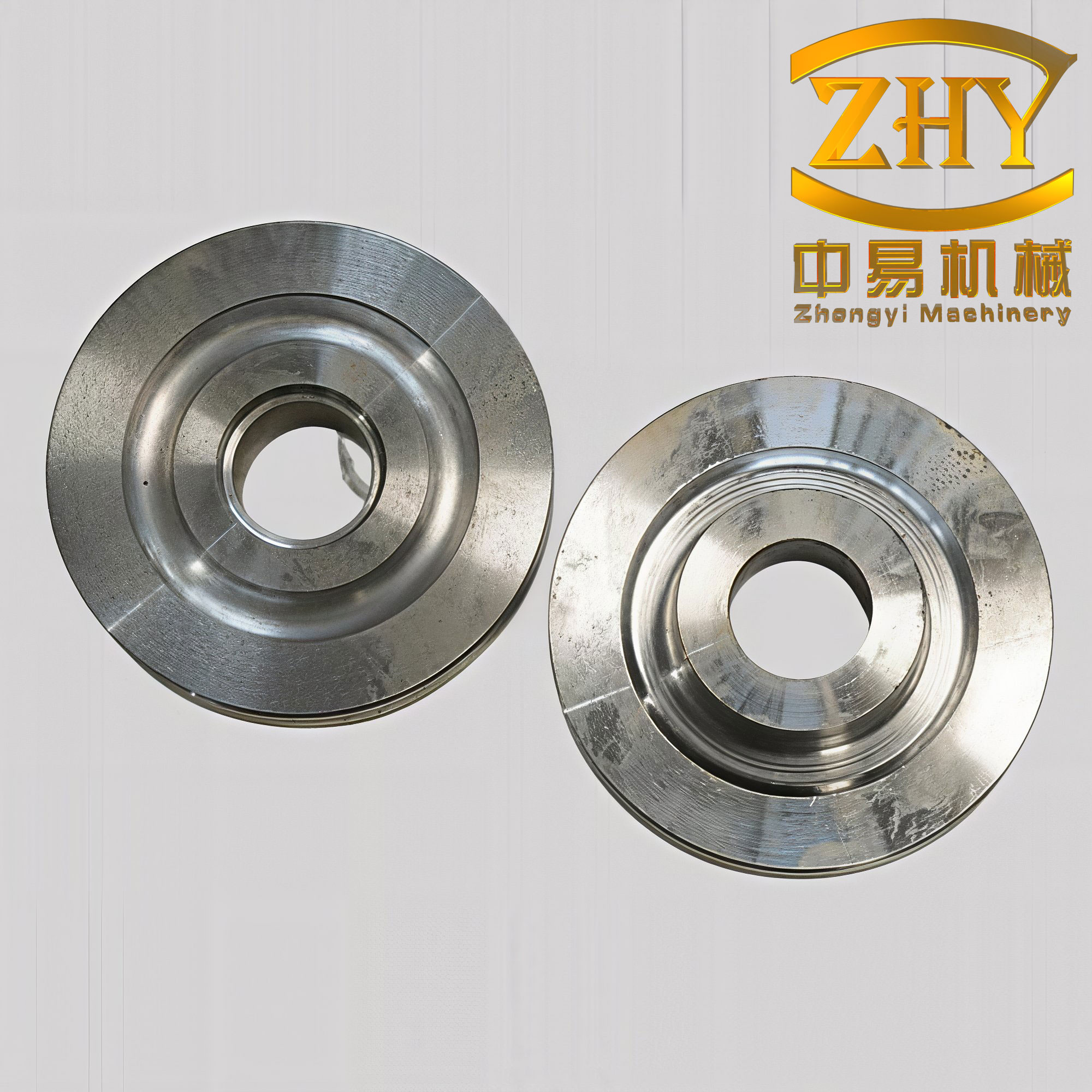
Physical validation of microstructure. I produced trial forged gear blanks with the optimized schedule on a precision rotary swaging machine and then sectioned the hollow gear shaft at four representative locations. The locations covered the outer step surface, the first step shoulder, the second step shoulder, and the region where metal flows along the mandrel step. I used scanning electron microscopy to examine the grain morphology and the degree of fibrous alignment. The following image shows a representative forged gear blank from the trial production, and I use it only as a visual reference for the external geometry of the workpiece family.
In the outer step region, I observed a mixture of deformed grains and remnants of original grains. The grain size decreased from the surface toward the interior, but the very outermost layer contained some larger grains. I attributed this to the combined effect of friction, local temperature loss, and the intense impact energy that first fragments near-surface grains and then provides a thermal path for limited boundary migration. In the first step shoulder, the grains were elongated along the local material flow direction, and the degree of elongation increased with accumulated strain. In the second step shoulder, the microstructure was more fibrous and more compact than in the first step shoulder. In the region where the metal flows around the mandrel step, the fibrous structure was particularly dense, with a strong alignment along the mandrel surface. This is consistent with the high local shear and compression that develop when forged gear blanks are reduced in wall thickness over a stepped mandrel.
Table 9. Microstructural observations at representative sections of forged gear blanks.
| Region | Grain morphology | Refinement trend | Fibrous alignment | Interpretation |
|---|---|---|---|---|
| Outer step surface | Deformed grains plus some original grains | Refinement increases from surface inward, then weakens | Weak to moderate near surface | Friction and cooling create a locally heterogeneous surface layer |
| First step shoulder | Elongated grains | Moderate refinement | Moderate, following local flow | Repeated hammer strikes accumulate strain but the reduction is moderate |
| Second step shoulder | Fine elongated grains | Stronger refinement than the first step | Strong fibrous structure | Larger local deformation promotes grain fragmentation and alignment |
| Mandrel step flow region | Dense, highly elongated grains | Strong refinement and densification | Strong, parallel to the mandrel surface | High local shear and compression close porosity and align the microstructure |
I summarized the grain refinement using a simple refinement ratio,
$$R_g=\frac{d_0}{d_f}$$
where \(d_0\) is the initial mean grain size and \(d_f\) is the final mean grain size. A larger \(R_g\) indicates stronger refinement. In forged gear blanks produced by rotary swaging, the refinement ratio is not uniform across the wall. It is highest in regions that experience multiple overlapping strikes and strong mandrel constraint, and it is lower at the extreme outer surface where friction and cooling can inhibit continuous recrystallization. The relation between grain size and strength can be expressed through the Hall-Petch relation,
$$\sigma_y=\sigma_0+k_y d^{-1/2}$$
and the corresponding hardness scaling can be written as
$$H=H_0+k_H d^{-1/2}$$
where \(H\) is hardness, \(H_0\) is the intrinsic hardness, and \(k_H\) is a material constant. This relationship helps explain why the regions with finer and more fibrous grains in forged gear blanks also show higher local hardness. It also explains why the hardness trend follows the local strain distribution rather than the geometric distance from the surface alone.
Microhardness response. I measured microhardness on the radial-axial section at the first step and the second step. For each location, I took six equally spaced points from the inner surface to the outer surface, and at each point I averaged three readings across the width direction. The average hardness at a given position was therefore
$$\bar{H}=\frac{1}{3}\sum_{s=1}^{3}H_s$$
where \(H_s\) is an individual indentation reading. I used a load of 100 g and a dwell time of 10 s. The measured trends are summarized in Table 10. Near the mandrel, the hardness was higher than in the mid-wall region. I attributed this to two effects. First, the metal flow during rotary swaging of forged gear blanks is concentrated near the mandrel, so the inner surface accumulates more effective strain. Second, the mandrel and coolant extract heat from the inner surface, which limits grain coarsening and preserves a finer substructure. This combination produces a harder inner layer even though the outer surface experiences the direct hammer impact.
Table 10. Relative microhardness trends in the optimized forged gear blanks.
| Region | Trend from inner surface to outer surface | Relative level compared with the first step | Main cause |
|---|---|---|---|
| First step, shaping segment | Hardness decreases from inner surface toward mid-wall, then stabilizes | Reference level | Moderate accumulated strain and partial mandrel constraint |
| First step, shoulder | Lower than the shaping segment at the same radial position | Slightly lower | Less dense fibrous structure and lower local strain |
| Second step, shaping segment | Hardness decreases from inner surface toward mid-wall, with a stronger gradient | Higher than the first step | Larger total deformation and stronger fibrous alignment |
| Second step, shoulder | Nonuniform, with local high-hardness bands | Higher than the first step shoulder | More severe radial reduction and mandrel-step flow constraint |
The shaping segment consistently showed higher hardness than the adjacent shoulder region. This is consistent with the microstructural observation that the shaping segment is more heavily deformed and more fully densified. For forged gear blanks, this difference is important because it means that the final shaping passes are not merely sizing passes; they also contribute to property improvement. The second step showed a higher surface hardness than the first step because the total radial deformation at the second step is larger. The larger deformation increases dislocation density and promotes fibrous alignment, both of which raise hardness. The hardness gradient from the inner surface to the outer surface also reflects the nonuniform strain distribution that is characteristic of rotary swaging. I did not observe a simple monotonic increase from inner to outer surface; instead, the highest values appeared near the mandrel, and the outer surface was influenced by friction and cooling.
Process implications for forged gear blanks. The results support several practical rules for rotary swaging of forged gear blanks. First, the radial reduction should be kept at the low end of the feasible window when folding is the primary concern. A reduction of 2.0 mm was sufficient to produce grain refinement when combined with a high rotation speed and multiple passes, but larger reductions increased the folding code rapidly. Second, the axial feed should be kept small to suppress the spiral ridge. A feed of 0.05 mm gave the best ridge response, and the simulation showed that the ridge depth was more sensitive to feed than to any other factor. Third, the rotation speed should be high enough to distribute the hammer strikes circumferentially. At 76 r·min-1, the folding response was minimized without a significant penalty in ridge depth. Fourth, the billet temperature should be high enough to lower flow stress but not so high that the surface becomes thermally soft and prone to marking. In my schedule, 830 °C provided a good balance. Fifth, the hammer radial velocity should be moderate to low; 7.5 mm·s-1 reduced impact severity and gave the best joint response.
Table 11. Practical process window for forged gear blanks derived from this study.
| Parameter | Preferred window | Reason | Risk if exceeded |
|---|---|---|---|
| Billet temperature | 800-830 °C | Lower flow stress and adequate fill | Coarse grains, oxidation, thermal softening |
| Relative axial feed | 0.05-0.10 mm | Suppresses spiral ridge | Ridge formation and uneven wall thickness |
| Rotation speed | 70-76 r·min-1 | Improves circumferential overlap | Localized folding and hammer marks |
| Radial reduction | 2.0-2.5 mm | Limits folding while allowing densification | Severe folding and mandrel overload |
| Radial velocity | 7.5-10.0 mm·s-1 | Reduces impact-induced surface damage | Surface tearing and excessive springback |
Discussion of robustness and limitations. I consider the optimized schedule to be robust within the range of forged gear blanks studied here, but I do not treat it as a universal recipe. The response surface is influenced by mandrel geometry, hammer profile, lubrication, and the number of passes. In particular, the folding response is sensitive to the local ratio between radial reduction and wall thickness. If the wall thickness is reduced further, the same radial reduction may produce a higher folding risk, and the feed may need to be reduced accordingly. The ridge response is sensitive to the axial feed per revolution and to the hammer contact length. If the contact length is increased, the same feed may produce a shallower ridge, which would allow a slightly higher feed and therefore higher productivity. I would therefore recommend a small confirmation design around the optimum whenever the tooling geometry changes. For forged gear blanks with a different step ratio, I would first adjust the radial reduction and feed, and I would keep the rotation speed high and the radial velocity low unless the surface quality shows otherwise.
I also note that the defect coding used here is ordinal. It is appropriate for screening, but it does not replace a full three-dimensional damage or ductile fracture model. A more refined study could use a normalized Cockcroft-Latham or Oyane damage parameter to quantify the folding risk continuously. Such a model would allow a more precise optimization of forged gear blanks with thin walls and large step changes. Another limitation is that the hardness measurements were taken on a limited number of sections. A full mapping of hardness and grain size over the entire forged gear blank would provide a more complete picture of property heterogeneity. Nevertheless, the agreement between the simulation trends, the grain morphology, and the hardness ranking gives me confidence that the selected schedule is physically meaningful.
Table 12. Summary of mechanisms and observable outcomes in forged gear blanks.
| Mechanism | Process condition | Microstructural outcome | Property outcome | Defect outcome |
|---|---|---|---|---|
| Repeated overlapping strikes | High rotation speed, low feed | More uniform circumferential strain | Higher and more uniform hardness | Lower folding code |
| Mandrel constraint | Moderate radial reduction | Fibrous alignment near inner surface | Higher inner-surface hardness | Densification and pore closure |
| Step flow | Larger reduction at the second step | Fine elongated grains near the step | Higher hardness at the second step | Local strain concentration if feed is too high |
| Surface friction and cooling | Contact with hammer and coolant | Heterogeneous outer layer | Lower hardness at the extreme surface than expected from strain alone | Risk of surface marking and ridge formation |
Conclusions. I draw the following conclusions from the orthogonal simulation and physical validation of forged gear blanks. (1) The optimized rotary swaging schedule is an initial billet temperature of 830 °C, a relative axial feed of 0.05 mm, a billet rotation speed of 76 r·min-1, a hammer radial reduction of 2.0 mm, and a hammer radial velocity of 7.5 mm·s-1. (2) The radial reduction is the dominant factor for folding, while the axial feed is the dominant factor for spiral ridge depth. Rotation speed is the second most important factor for folding, and temperature, radial reduction, and radial velocity have comparable secondary effects on ridge depth. (3) The optimized schedule suppresses both folding and spiral ridge formation in forged gear blanks while still providing sufficient accumulated strain for grain refinement and densification. (4) Grain refinement increases with deformation and is strongest in the second step and in the mandrel-step flow region; the outer surface can remain heterogeneous because of friction and cooling. (5) Rotary swaging produces a fibrous microstructure in forged gear blanks, and the degree of fibrous alignment follows the local material flow. (6) The second step has a higher surface microhardness than the first step because the total radial deformation is larger, and the shaping segment is harder than the adjacent shoulder because it is more heavily deformed and denser. (7) For production control, I would prioritize feed and radial reduction tolerances, keep the rotation speed high, keep the radial velocity low to moderate, and allow a temperature window of approximately 800-830 °C for forged gear blanks of this geometry.
Table 13. Final optimized result and verification summary.
| Item | Result for forged gear blanks |
|---|---|
| Optimized schedule | A4B1C4D1E1 |
| Initial temperature | 830 °C |
| Relative axial feed | 0.05 mm |
| Rotation speed | 76 r·min-1 |
| Radial reduction | 2.0 mm |
| Radial velocity | 7.5 mm·s-1 |
| Folding response | No significant folding in the optimized simulation |
| Spiral ridge response | No significant ridge in the optimized simulation |
| Microstructure | Fibrous and refined, with stronger refinement at the second step and mandrel flow region |
| Microhardness | Higher near the mandrel, higher at the second step than at the first step, and higher in the shaping segment than in the shoulder |
Overall, I find that the combination of orthogonal experimentation and thermomechanical simulation is an effective way to optimize rotary swaging for forged gear blanks. The range analysis identifies which factors must be controlled tightly, while the physical validation confirms that the predicted deformation pattern actually produces the intended microstructure and hardness distribution. The resulting process window is not only a set of numerical values; it is a design logic for forged gear blanks in which feed and radial reduction control defect formation, rotation speed controls circumferential uniformity, and temperature and radial velocity control the balance between flow and surface integrity.