
In the realm of mechanical engineering and design, spur gears represent one of the most fundamental and widely used power transmission components. Their precision and efficiency are paramount in countless applications, from automotive systems to industrial machinery. As a design engineer, I often encounter the challenge of creating accurate three-dimensional models for spur gears. Traditional modeling approaches, while feasible, become tedious and time-consuming when design iterations are required—such as altering the number of teeth, module, or pressure angle. Each change necessitates a complete re-calculation and re-modeling process. To address this inefficiency, I have explored and implemented a parametric modeling methodology for involute spur gears using Pro/Engineer (Pro/E) software. This approach allows for the creation of a fully associative and intelligent model where modifying a few key parameters automatically regenerates the entire gear geometry. This article details my comprehensive process for building such a parametric model, emphasizing the use of relations, equations, and feature-based modeling to achieve a high degree of design automation and resource savings.
The core principle behind this parametric system is the mathematical definition of the involute tooth profile. The involute curve is the standard form for modern gear teeth due to its favorable properties, such as constant velocity ratio and ease of manufacturing. An involute can be defined as the locus of a point on a taut string as it unwinds from a base circle. This geometric definition translates directly into a set of parametric equations that can be programmed within Pro/E’s relation editor. By driving the entire model with these equations and a set of master parameters, the model becomes dynamic and adaptable.
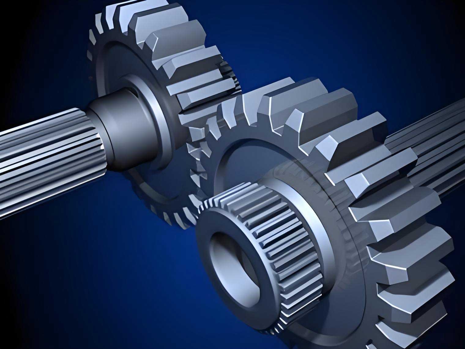
The design of any set of spur gears begins with a set of fundamental geometric parameters. These parameters are interlinked through standardized gear theory formulas. In my parametric model, I define these as initial input values and derived relations. The primary parameters serve as the independent variables that the designer can modify to generate a new gearset instantly.
| Parameter Name | Symbol | Initial Value / Formula | Description |
|---|---|---|---|
| Module | M | 3 mm | The ratio of pitch diameter to number of teeth, defining tooth size. |
| Number of Teeth | Z | 25 | The count of teeth on the gear. |
| Pressure Angle | ALPHA | 20° | The angle between the line of action and the line tangent to the pitch circle. |
| Addendum Coefficient | HAX | 1 | Factor for calculating addendum height, typically 1 for standard gears. |
| Dedendum Coefficient | CX | 0.25 | Factor for calculating dedendum height, ensuring clearance. |
| Face Width | B | 10 mm | The axial length of the gear teeth. |
| Profile Shift Coefficient | X | 0 | Modification coefficient for non-standard gears; zero for standard design. |
| Pitch Diameter | D | $$D = M \times Z$$ | The diameter of the imaginary pitch circle where teeth theoretically mesh. |
| Addendum | HA | $$HA = (HAX + X) \times M$$ | Radial distance from pitch circle to tooth tip. |
| Dedendum | HF | $$HF = (HAX + CX – X) \times M$$ | Radial distance from pitch circle to tooth root. |
| Outside Diameter | DA | $$DA = D + 2 \times HA$$ | Diameter of the gear’s outer circumference (tip circle). |
| Root Diameter | DF | $$DF = D – 2 \times HF$$ | Diameter of the gear’s root circle. |
| Base Circle Diameter | DB | $$DB = D \times \cos(ALPHA)$$ | Diameter of the circle from which the involute is generated. |
The parametric modeling process for these spur gears in Pro/E is a sequential and logical workflow. It starts by embedding the above parameters and relations into the software’s knowledge engine, followed by the geometric construction of curves and solids.
The first step is to create a new part file in Pro/E’s part design mode. I then access the parameters dialog to declare all the independent parameters listed in Table 1. This is done by adding each parameter name (e.g., M, Z, ALPHA), assigning a initial numeric value, and specifying its type (e.g., real number, integer). Following the parameter declaration, I use the “Relations” editor to establish the mathematical links between parameters. Here, I input all the derived formulas, such as `D = M*Z`, `DB = D*cos(ALPHA)`, and so on. This action configures Pro/E’s regeneration engine to compute these dependent values automatically whenever a master parameter like M or Z is changed. This foundation is critical for all subsequent geometry.
With the parameters and relations set, I begin sketching the key reference geometry—the four critical circles for spur gears: the root circle, pitch circle, base circle, and outside circle. I create a sketch with four concentric circles of arbitrary initial diameters. After exiting the sketch, I immediately open the Relations editor again. Here, I associate the sketch dimensions (system-generated symbols like d0, d1, etc.) with my defined parameter names using assignment relations:
$$ \text{d0} = DF $$
$$ \text{d1} = D $$
$$ \text{d2} = DB $$
$$ \text{d3} = DA $$
Upon regenerating the model, these four circles resize precisely according to the current parameter values. This visual confirmation ensures the parameters are driving the geometry correctly. The base circle is particularly important as it is the genesis for the involute tooth profile.
The creation of the involute curve is the most technically intricate part of modeling spur gears. Pro/E provides a “Curve from Equation” tool for this purpose. I select a coordinate system and choose the Cartesian coordinate type. The involute of a circle is defined parametrically. For a base circle of radius \( r_b = DB/2 \), the Cartesian coordinates of a point on the involute are given by:
$$ x = r_b (\cos(\theta) + \theta \sin(\theta)) $$
$$ y = r_b (\sin(\theta) – \theta \cos(\theta)) $$
Where \( \theta \) is the involute roll angle in radians. To adapt this for Pro/E’s equation editor, which uses a parameter `t` ranging from 0 to 1, I define a variable `ang` that maps `t` to a suitable roll angle range. A common formulation to generate a sufficient length of involute is:
$$
\begin{aligned}
&\text{ang} = 90 * t \\
&r = DB / 2 \\
&s = (\pi * r * t) / 2 \quad \text{(arc length)} \\
&xc = r * \cos(\text{ang}) \\
&yc = r * \sin(\text{ang}) \\
&x = xc + (s * \sin(\text{ang})) \\
&y = yc – (s * \cos(\text{ang}))
\end{aligned}
$$
In these equations, `ang` is treated in degrees for the trigonometric functions within Pro/E’s environment, and the `s` variable approximates the unwound string length. This set of equations, when entered, generates one flank of an involute tooth profile originating from the base circle. This curve is fundamental for defining the tooth shape of our spur gears.
To complete the tooth profile contour for a single tooth, I need a segment of the involute from the root circle to the outside circle, plus the fillet at the root. I create a new sketch on a datum plane through the gear axis. In this sketch, I use the “Use Edge” tool to reference the root circle (DF), the outside circle (DA), and the generated involute curve. I then sketch the opposite flank of the tooth. Since a gear tooth is symmetric about a line drawn from the center of the gear through the midpoint of the tooth on the pitch circle, I create this centerline. The second involute is generated by mirroring the first one about this tooth centerline. The precise angle for this centerline is half the tooth thickness angle at the pitch circle. The circular tooth thickness at the pitch circle is theoretically \( \pi * M / 2 \) for a standard gear. Therefore, the angle from the start of one tooth to its centerline on the pitch circle is \( 360 / (4 * Z) \) or \( 90 / Z \) degrees. I create a datum line at this angle from a starting reference plane. After mirroring the involute, I connect the ends of the involute curves to the root circle with radial lines or fillet arcs, trimming away excess geometry to form a closed loop. This closed loop defines the cross-section of one tooth for our spur gears.
The next phase is to create the three-dimensional solid body. I first extrude the root circle cylinder to establish the gear blank. The extrusion depth is set equal to the face width parameter `B`. I add a relation to link the extrusion depth dimension symbol (e.g., d5) to B (`d5 = B`). This ensures the gear width updates with parameter changes. Following this, I extrude the single tooth profile sketch as a positive protrusion from the gear blank, again with an extrusion depth equal to `B` (and similarly linked via a relation). This results in a solid model with one complete tooth. Proper fillet geometry at the tooth root is crucial for stress reduction. I apply a fillet feature to the root corners. The size of this fillet can also be parameterized based on the module. A common relation I use is:
$$
\text{IF } HAX >= 1 \\
\quad \text{fillet\_radius} = 0.38 * M \\
\text{ENDIF} \\
\text{IF } HAX < 1 \\
\quad \text{fillet\_radius} = 0.46 * M \\
\text{ENDIF}
$$
This conditional statement in the Relations editor automatically adjusts the fillet size depending on the addendum coefficient, enhancing the model’s intelligence and adherence to design standards for spur gears.
Creating the remaining teeth is achieved through a pattern operation. However, a direct pattern of the first tooth feature requires careful setup. My preferred method involves first creating a second tooth using the “Copy” and “Paste Special” commands with a “Rotational Move” transformation. I select the axis of the gear as the rotation reference. The rotation angle for this move is not a fixed number but is driven by the relation \( 360 / Z \). During the paste operation, Pro/E prompts to add this dimension as a relation, which I confirm. This creates a second, identical tooth feature positioned exactly one tooth space away. Now, with this second tooth feature (which is a copied, rotated instance), I can apply a dimensional pattern. I select the rotational move angle dimension as the direction for patterning. Initially, I enter an arbitrary increment. After the pattern feature is created, I edit its parameters through the Relations editor. I set the pattern increment dimension (e.g., p6) to \( 360/Z \) and, critically, I set the total number of instances in the pattern to \( Z – 1 \). This is because the pattern will create instances of the second tooth, and together with the original first tooth, they will total Z teeth. The relation entry looks like:
$$ \text{p6} = 360 / Z $$
$$ \text{p7} = Z – 1 $$
Where p6 is the pattern increment symbol and p7 is the pattern instance count symbol. Upon regeneration, the software calculates the correct angle and generates the full set of teeth instantly. This pattern is fully associative; changing Z automatically updates the number and angular position of all teeth on the spur gears.
The final step involves adding common manufacturing and assembly features to the gear model, such as a keyway, hub, or bore. For simplicity, I demonstrate with a keyway. I create a sketch on a face of the gear blank, defining a standard keyway profile relative to the bore diameter. This is extruded as a cut feature. While the keyway dimensions might be standardized based on shaft size, they can also be linked to gear parameters (e.g., a function of the root diameter) for full parameterization, though for clarity in this model, they may be left as independent features or tied to a separate set of parameters.
To solidify the understanding of the parameter inter-dependencies and the modeling sequence, the following table summarizes the core modeling steps and their corresponding Pro/E tools or actions:
| Step | Objective | Pro/E Tool/Action | Key Parameters/Relations Involved |
|---|---|---|---|
| 1. Foundation | Declare independent gear parameters. | Tools > Parameters | M, Z, ALPHA, HAX, CX, B, X |
| 2. Knowledge Embedding | Define dependent geometric parameters. | Tools > Relations | D = M*Z, DB = D*cos(ALPHA), DA, DF, HA, HF |
| 3. Reference Geometry | Create the four defining circles. | Sketch > Circle; Tools > Relations | Linking sketch dimensions (d#) to DA, DF, D, DB |
| 4. Tooth Profile Definition | Generate the involute curve. | Insert > Model Datum > Curve > From Equation | Involute equations using DB, t, π |
| 5. Single Tooth Sketch | Create closed 2D profile for one tooth. | Sketch (Use Edge, Mirror, Trim) | References to DA, DF, involute; symmetry about 90/Z angle |
| 6. Solid Gear Blank | Create the 3D cylindrical body. | Extrude (Protrusion) | Depth = B (linked via relation) |
| 7. Single Tooth Solid | Extrude the tooth profile. | Extrude (Protrusion) | Depth = B; Optional root fillet relation (0.38*M) |
| 8. Duplicate Tooth | Create a second tooth correctly positioned. | Copy > Paste Special > Rotational Move | Move angle = 360 / Z (added as relation) |
| 9. Complete Tooth Set | Pattern the second tooth around the axis. | Pattern (Dimension Pattern) | Increment = 360/Z; Number of Instances = Z-1 (via Relations) |
| 10. Detailing | Add keyway, bore, chamfers. | Extrude (Cut), Hole, Chamfer | Dimensions can be fixed or parameterized. |
The power of this parametric approach for designing spur gears cannot be overstated. Once this master model is constructed, generating a new gear design is a matter of seconds. For instance, to create a gear with a module of 4 mm and 40 teeth, I simply open the parameters dialog, change M to 4 and Z to 40, and then regenerate the model. Pro/E automatically recalculates all diameters (D becomes 160 mm, DB becomes approximately 150.35 mm for a 20° pressure angle, etc.), redraws the involute based on the new base circle, repositions the tooth centerline, updates the pattern count to 39 instances, and regenerates the solid geometry. The entire gear updates cohesively. This eliminates manual recalculations, redrawing, and the high potential for error inherent in manual redesign processes. It standardizes the design process for spur gears within an organization, ensuring consistency and accuracy across projects.
Furthermore, this parametric model serves as an excellent foundation for more advanced applications. It can be integrated into Pro/E’s family table to create a table-driven standard part library of spur gears. It can also be used in mechanism simulations for motion analysis or exported for finite element analysis (FEA) to study stress concentrations under load—all while maintaining the parametric links. The model also enforces good design practice by inherently respecting the geometric constraints of involute spur gears. For example, if a user inputs a very low number of teeth, the regenerated model will visibly show issues like undercutting if the base circle becomes larger than the root circle, providing immediate visual feedback.
In conclusion, the parametric modeling of involute spur gears using Pro/Engineer represents a significant leap in design efficiency and intellectual property management. The methodology I have detailed—centered on defining master parameters, embedding geometric relations, leveraging the involute equation, and using associative patterning—transforms a static model into a dynamic, intelligent design template. This approach liberates the designer from repetitive tasks, allowing focus on optimization, analysis, and innovation. Whether for educational purposes to teach gear geometry or for industrial use in rapid prototyping and custom gear manufacturing, mastering this parametric technique is invaluable for any engineer working with spur gears. The ability to instantly visualize the impact of a parameter change fosters deeper understanding and enables the exploration of design alternatives that would otherwise be impractical due to time constraints. Ultimately, this parametric paradigm is not just about modeling a single component; it’s about building a flexible, reusable, and robust digital asset that streamlines the entire product development lifecycle for systems involving spur gears.