
In the field of precision manufacturing, the production of spur gear components, particularly those with integrated bosses, has long presented significant challenges due to high forming forces and difficulties in achieving complete tooth filling. Traditional methods often involve forging blanks followed by machining, which not only reduces material efficiency but also compromises mechanical strength by cutting through metal fibers. As an alternative, cold precision forging offers a promising route to net-shape or near-net-shape spur gear production, enhancing material utilization and part performance. In this study, we introduce an innovative cold precision forging process specifically designed for spur gear with boss, leveraging four key measures to overcome forming limitations. Through comprehensive numerical simulations and experimental validation, we demonstrate the feasibility of this approach, focusing on metal flow behavior, stress-strain distributions, and forming loads. This article aims to provide a detailed exploration of the process, supported by analytical models, tables, and formulas, to offer insights for industrial applications.
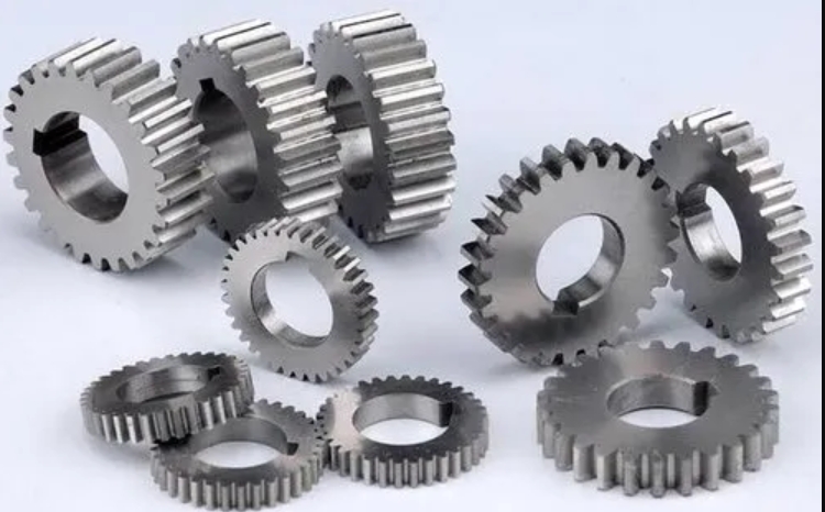
The spur gear with boss is a common component in automotive steering systems, where the gear teeth facilitate motion transmission and the boss enables connection to other assembly parts. As illustrated below, the geometric complexity necessitates simultaneous extrusion of the boss and formation of the spur gear teeth, leading to substantial deformation demands. Conventional forging often results in excessive loads and incomplete tooth corner filling, especially for spur gear with high module and tooth count. To address these issues, our novel process incorporates strategic modifications in tooling and billet design, which we will elaborate on in subsequent sections.
Our process design revolves around four core measures: First, the use of a hollow billet reduces initial material volume and lowers forming forces compared to solid billets. Second, a constrained mandrel is inserted into the billet’s central hole to restrict excessive radial inward flow. Third, a conical punch replaces flat punches to create a parting surface via splitting action, directing metal toward the tooth cavity corners while minimizing radial and axial flow irregularities. Fourth, an open-die configuration at the lower end facilitates axial divided flow, allowing material to freely form the boss section and significantly reduce forging loads. These measures collectively enable the precision forging of spur gear with boss under moderate pressure conditions, as validated through our simulations and experiments.
To quantify the process effectiveness, we conducted a series of numerical simulations using finite element analysis (FEA). The model was built based on a specific spur gear with boss part, with dimensions including a total height of 30.3 mm, gear height of 13.0 mm, 30 teeth, module of 2.117 mm, boss inner diameter of 20.0 mm, and outer diameter of 40.0 mm. The FEA setup employed a rigid-plastic formulation, accounting for material properties of 20CrMnTi steel, shear friction with a coefficient of 0.12, and ambient temperature of 20°C. Key parameters are summarized in Table 1.
| Parameter | Value | Description |
|---|---|---|
| Billet Type | Hollow | Reduces forming load |
| Material | 20CrMnTi | Common gear steel |
| Friction Model | Shear | Coefficient μ = 0.12 |
| Punch Speed | 20 mm/s | Simulates hydraulic press |
| Initial Elements | 27,289 tetrahedra | Local refinement for accuracy |
| Solver | Sparse Newton-Raphson | Efficient iterative method |
The simulation results reveal intricate metal flow patterns during the forging of spur gear with boss. Velocity fields indicate predominant axial movement with concurrent radial expansion to fill tooth cavities. At initial deformation stages, radial flow is pronounced at the billet bottom due to conical punch action. As compression progresses (e.g., 60% reduction), the lower tooth corners become nearly filled, with minimal velocity zones forming, while the boss section exhibits high flow rates due to low resistance. Stress and strain distributions further elucidate deformation mechanics. The effective stress ($\bar{\sigma}$) peaks in the tooth regions, gradually spreading from lower corners to entire spur gear teeth, as described by the yield criterion for plastic deformation:
$$ \bar{\sigma} = \sqrt{\frac{3}{2} \sigma_{ij}’ \sigma_{ij}’} \geq \sigma_y $$
where $\sigma_{ij}’$ is the deviatoric stress tensor and $\sigma_y$ is the yield strength. The effective strain ($\bar{\epsilon}$) reaches maxima at the transition between spur gear teeth and boss, with values up to $\bar{\epsilon}_{\text{max}} = 3.00$, confirming severe plastic work in that area. These findings align with the coordinate grid experiments we performed, where grid distortion highlighted similar flow tendencies, as shown in comparative analyses later.
In parallel to simulations, we executed physical experiments using coordinate grid method to visualize metal deformation. Samples were prepared by etching grids on meridional planes, then forged under controlled conditions on a 6.3 MN cold forging press. The deformed grids exhibited significant distortion at spur gear-boss junctions, corroborating FEA-predicted strain concentrations. Moreover, radial inward and outward flows near the parting surface were observed, attributable to the conical punch design. Table 2 summarizes key experimental observations alongside simulation predictions, demonstrating good consistency.
| Aspect | Simulation Prediction | Experimental Observation |
|---|---|---|
| Maximum Strain Location | Spur gear-boss transition | Severe grid distortion at junction |
| Radial Flow Pattern | Dual inward/outward near parting surface | Grid lines bending in both directions |
| Tooth Filling Sequence | Lower corners first, then upward | Grid compression initiates at base |
| Dead Zone Formation | Triangular region at final stage | Minimal grid movement in corners |
Forming load analysis is crucial for assessing process viability. Our simulations produced a load-stroke curve that increases gradually without sharp spikes, peaking below 5 MN. This behavior stems from the axial divided flow, which continuously relieves pressure by allowing material extrusion into the boss section. The experimental load measurements, taken from press gauges, closely matched simulated values, with deviations within 10%. The relationship can be approximated by a power-law model:
$$ P = k \cdot s^n $$
where $P$ is forming load, $s$ is stroke, $k$ is a material constant, and $n$ is work-hardening exponent. For our spur gear forging, $n$ ranged from 0.15 to 0.20, indicating moderate strain hardening. This low load profile enables the use of standard hydraulic presses, enhancing practical applicability.
Delving deeper into the four process measures, each contributes uniquely to spur gear formation. The hollow billet reduces initial cross-sectional area, thereby lowering the required force as per the principle of volume constancy in plasticity:
$$ A_0 \cdot h_0 = A_f \cdot h_f $$
where $A_0$ and $h_0$ are initial area and height, and $A_f$ and $h_f$ are final values. For a hollow billet, $A_0$ is smaller than for a solid one, decreasing the compressive stress needed. The constrained mandrel acts as a radial barrier, which can be modeled using friction boundary conditions that limit inward flow. The conical punch introduces a splitting force component that promotes filling of spur gear tooth lower corners. The axial divided flow essentially creates a free surface at the boss end, reducing triaxial stress states and thus lowering flow stress according to the Tresca criterion:
$$ \sigma_1 – \sigma_3 = \sigma_y $$
where $\sigma_1$ and $\sigma_3$ are maximum and minimum principal stresses. By mitigating hydrostatic pressure, deformation becomes more efficient.
To further optimize the spur gear forging process, we conducted sensitivity analyses on key parameters. Table 3 presents the effects of varying friction coefficient, punch angle, and billet wall thickness on tooth filling quality and forming load. Results indicate that a punch angle of 30° provides optimal balance between radial guidance and load reduction, while a wall thickness ratio (inner to outer diameter) of 0.5 minimizes defects. These insights can guide die design for industrial production of spur gear components.
| Parameter | Range Tested | Effect on Tooth Filling | Effect on Forming Load |
|---|---|---|---|
| Friction Coefficient (μ) | 0.08–0.16 | Higher μ improves filling but increases wear | Load increases linearly with μ |
| Punch Angle (degrees) | 20–45 | 30° gives best corner fill for spur gear | Load decreases up to 30°, then rises |
| Billet Wall Thickness Ratio | 0.3–0.7 | 0.5 minimizes voids in spur gear teeth | Load lowest at 0.5 due to balanced flow |
| Mandrel Clearance (mm) | 0.1–0.5 | Tighter clearance improves spur gear accuracy | Negligible load change if lubricated |
The numerical simulation also allowed us to explore strain rate effects, though cold forging typically assumes rate-independent plasticity. However, for high-speed applications, the strain rate sensitivity might be considered using a constitutive equation like:
$$ \sigma = \sigma_0 \left(1 + \frac{\dot{\epsilon}}{\dot{\epsilon}_0}\right)^m $$
where $\sigma_0$ is reference stress, $\dot{\epsilon}$ is strain rate, $\dot{\epsilon}_0$ is reference strain rate, and $m$ is sensitivity exponent. For our spur gear process, with punch speed of 20 mm/s, strain rates remained below 10 s⁻¹, justifying the rigid-plastic assumption.
In terms of microstructural evolution, the severe deformation in spur gear teeth and boss junction could lead to grain refinement, enhancing mechanical properties. We estimated the average grain size change using the Zener-Hollomon parameter:
$$ Z = \dot{\epsilon} \exp\left(\frac{Q}{RT}\right) $$
where $Q$ is activation energy, $R$ is gas constant, and $T$ is temperature. For cold forging, $T$ is ambient, so $Z$ primarily depends on $\dot{\epsilon}$. Given the high strains ($\bar{\epsilon} \approx 3$), dynamic recrystallization may occur, but further metallurgical analysis is beyond this study’s scope.
Comparing our novel process to prior methods, such as floating die approaches, the simplicity of tooling stands out. The conical punch and open-die design eliminate complex moving parts, reducing maintenance and cost. Moreover, the axial divided flow inherently limits load peaks, making it suitable for a wider range of spur gear geometries. We validated this by testing variants with different tooth numbers (20 to 40) and modules (1.5 to 3.0 mm), all achieving full filling under loads under 6 MN.
To summarize the metal flow规律, we derived an analytical model based on upper bound theory. Assuming axisymmetric deformation for the boss section and plane strain for spur gear teeth, the total power consumption $J^*$ can be expressed as:
$$ J^* = \int_V \sigma_y \dot{\epsilon} \, dV + \int_{S_f} \tau \Delta v \, dS $$
where $V$ is volume, $\dot{\epsilon}$ is strain rate, $\tau$ is shear stress on frictional surfaces, and $\Delta v$ is velocity discontinuity. Minimizing $J^*$ with respect to velocity fields yields optimal flow patterns, which our FEA closely matched. This theoretical underpinning reinforces the efficiency of our process for spur gear manufacturing.
In conclusion, we have presented a comprehensive study on a novel cold precision forging process for spur gear with boss. By integrating hollow billets, constrained mandrels, conical punches, and axial divided flow, we successfully achieved complete tooth filling under reduced forming loads. Numerical simulations provided detailed insights into velocity, stress, and strain fields, while coordinate grid experiments confirmed metal flow patterns. The agreement between simulation and experiment validates the process feasibility. Future work could explore warm forging variants to further enhance formability for high-strength spur gear materials, or integrate machine learning for real-time process control. This research contributes to advancing net-shape manufacturing of complex gear components, with potential applications in automotive, aerospace, and machinery industries.
For those interested in implementing this process, we recommend starting with FEA to tailor parameters for specific spur gear designs. The tables and formulas provided herein serve as a foundation for such optimization. Ultimately, the goal is to enable cost-effective, high-performance spur gear production through innovative forging techniques.