
The relentless pursuit of higher precision and performance in modern manufacturing has placed significant demands on gear production technologies. Among various forming processes, cold precision forging stands out for its ability to produce near-net-shape components with excellent mechanical properties. However, the extremely high forming loads associated with fully cold forging of complex shapes like spur gears often lead to accelerated die wear and reduced tool life. To address this challenge, a hybrid warm forging-cold sizing process has emerged as a highly effective solution. This process involves first producing a gear preform through warm forging, which significantly lowers flow stress, followed by a final cold precision sizing operation to achieve the required dimensional accuracy and surface finish. The cold sizing stage is critical for final quality, yet it introduces complex elastic interactions between the deforming spur gear and the constraining die. During sizing, the die cavity elastically expands under high internal pressure, and simultaneously, the spur gear itself undergoes elastic deformation. Upon ejection from the die, the stored elastic strain energy in the spur gear is released, causing a springback or elastic recovery. The combined effect of die elastic expansion and gear elastic recovery leads to deviations between the final spur gear dimensions and the nominal die cavity dimensions. For high-precision applications, predicting and compensating for these elastic effects is paramount. This article delves into the elastic deformation behavior during the cold precision sizing of spur gears, employing a coupled elastoplastic-elastic finite element analysis to predict the final dimensional deviation. The goal is to establish a predictive framework that can inform die design corrections, ultimately enabling the manufacture of spur gears with superior dimensional accuracy.
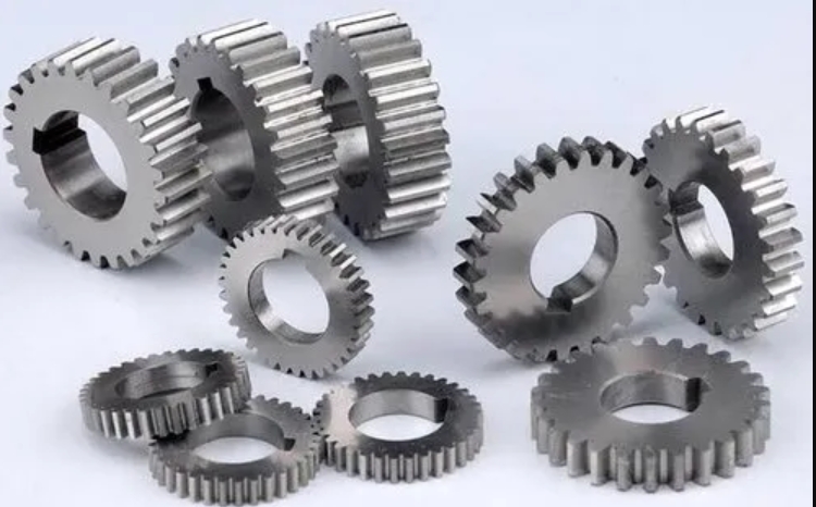
The cold precision sizing process for a spur gear can be succinctly described as a push-through operation. A pre-formed spur gear blank, which has a deliberate allowance or sizing amount on its tooth profile, is placed into a precision die cavity. A punch then forces the spur gear blank through the die. The excess material on the tooth flanks is squeezed out, primarily flowing axially to form a flash or upset at the top of the gear. This process calibrates the tooth profile, improves surface finish, and enhances geometric accuracy. The sizing amount, defined as the radial difference between the preform and the final tooth profile, is a critical parameter. If it is too small, incomplete filling and insufficient work hardening occur. If it is too large, forming loads increase excessively. The minimum theoretical sizing amount ($\delta_{min}$) required to ensure plastic deformation over the entire tooth surface can be estimated from the material’s yield criterion and the geometry of the spur gear. For a material with yield strength $\sigma_s$ and Young’s modulus $E$, the necessary true strain for yielding is $\epsilon = \sigma_s / E$. Relating this to the cross-sectional area change of the spur gear tooth from the preform ($A_0$) to the final shape ($A$) gives:
$$\epsilon = \ln\left(\frac{A_0}{A}\right)$$
Therefore, the minimum sizing amount is derived from the area difference corresponding to this strain. For a typical spur gear material like 20CrMnTi ($\sigma_s \approx 850$ MPa, $E \approx 205$ GPa), $\epsilon \approx 4.15 \times 10^{-3}$. For a spur gear with module 3 and 18 teeth, this translates to a minimum radial sizing amount of approximately 0.082 mm. In practice, a slightly larger value, such as 0.1 mm, is often selected to ensure robust process conditions.
To accurately simulate the complex interactions during cold sizing of a spur gear, a three-dimensional coupled Finite Element Model (FEM) is established. The model distinguishes between different deformation regimes. The spur gear workpiece is modeled as an elastoplastic body, obeying a material hardening law to capture its plastic flow and elastic springback. The punch is treated as a rigid body. Crucially, the die assembly is modeled as an elastic deformable body. In advanced applications, a prestressed compound die (with an inner ring and an outer shrink-fit ring) is used to withstand high pressures. This compound die structure is included in the model, with both the inner and outer rings defined as elastic bodies with their respective material properties (e.g., YG20 carbide for the inner ring, 40Cr steel for the outer ring). A symmetry model of one tooth space (1/18th of the full spur gear) is analyzed to save computational cost. The meshing is critical for accuracy; hexahedral elements with local refinement along the active involute profile of the spur gear and the corresponding die cavity are employed. Contact conditions with friction are defined between the spur gear and the die/punch surfaces. The simulation solves the coupled problem: the elastoplastic deformation of the spur gear exerts pressure on the elastic die, causing it to expand, which in turn alters the boundary conditions for the spur gear’s deformation.
| Component | Material | Young’s Modulus (GPa) | Poisson’s Ratio | Model Definition |
|---|---|---|---|---|
| Spur Gear Workpiece | 20CrMnTi | 205 | 0.30 | Elastoplastic Body |
| Die Inner Ring | YG20 | 580 | 0.22 | Elastic Body |
| Die Outer Ring | 40Cr | 209 | 0.30 | Elastic Body |
| Punch | Tool Steel | 210 | 0.30 | Rigid Body |
The metal flow during the cold sizing of the spur gear is predominantly axial. The velocity field from the simulation shows that material from the tooth flank is displaced upwards, forming the flash at the top end of the spur gear. A small radial inward flow component is also observed at the region contacting the die’s sizing land. The radial displacement distribution on the formed spur gear is relatively uniform along the tooth width (face width), but shows increased displacement (curling) at the top and bottom free ends. This end effect occurs because the material at the axial extremities is less constrained and can more easily deform under the radial pressure from the die.
The elastic expansion of the die cavity is not uniform. To quantify this, nodes on the die’s involute surface are tracked. The displacement of these nodes, resolved in the direction normal to the tooth profile, represents the local die expansion. Analysis is performed along two orthogonal directions on the spur gear tooth surface: the profile direction (from the root/fillet towards the tip along the involute) and the axial direction (along the face width from bottom to top).
Die Expansion Along the Tooth Profile: The normal expansion of the die cavity generally increases from the base circle region towards the tip circle of the spur gear. This trend can be attributed to the changing geometry of the involute. The pressure from the spur gear acts radially inward. This radial force can be decomposed into normal and tangential components relative to the tooth profile. The angle between the radial direction and the tangent to the involute (the involute roll angle) increases from the base circle to the tip. Consequently, for a given radial pressure, the normal component (which causes die cavity expansion) becomes larger towards the tip of the spur gear. Near the very tip, the expansion might slightly decrease due to a reduction in contact pressure caused by the slight curling of the spur gear’s top edge.
Die Expansion Along the Tooth Axial Direction: The die expansion typically increases from the bottom (entry side) to the top (exit side) of the die cavity. This is because the plastic deformation of the spur gear accumulates as it is pushed through the die. The sizing (reduction) is fully achieved at the exit, meaning the material at the top region of the spur gear has undergone the full prescribed strain, exerting maximum pressure on the die. Therefore, the elastic response of the die is greatest in this region. Similar to the profile, a slight reduction may occur at the very top edge due to the aforementioned curling effect.
Upon ejection, the spur gear undergoes elastic recovery (springback). The stored elastic strain energy from the plastic deformation phase is released, causing the spur gear tooth to expand radially outwards. The analysis of nodal displacements on the spur gear surface after unloading reveals its springback pattern.
Gear Springback Along the Tooth Profile: The elastic recovery of the spur gear is also non-uniform. The springback displacement in the normal direction tends to increase from the base circle towards the tip of the spur gear. This is again related to the involute geometry. The elastic strain is approximately proportional to the applied stress during sizing. As the normal pressure from the die was higher towards the tip (causing larger die expansion), the corresponding elastic strains induced in the spur gear material are also larger in that region. Upon release, these larger strains recover, leading to greater springback at the tip of the spur gear.
Gear Springback Along the Tooth Axial Direction: The springback magnitude generally increases from the bottom to the top of the spur gear tooth. This correlates with the accumulated plastic deformation; the top section of the spur gear, which was sized last, has experienced the highest level of plastic strain and thus has stored more elastic strain energy. This results in greater elastic recovery. The bottom free end may also show significant springback because it is less constrained and can recover more freely.
The final dimensional deviation of the cold-sized spur gear from the nominal design is the cumulative result of two sequential elastic effects: first, the die expands elastically during the forming process, meaning the spur gear is actually formed inside a slightly larger cavity than the nominal one. Second, after ejection, the spur gear itself springs back, becoming even larger. Therefore, the total dimensional error ($\Delta D_{total}$) at any point on the spur gear tooth can be expressed as the sum of the die elastic expansion ($\delta_{die}$) and the gear elastic recovery ($\delta_{gear}$):
$$\Delta D_{total} = \delta_{die} + \delta_{gear}$$
Both $\delta_{die}$ and $\delta_{gear}$ are functions of position on the tooth profile and along the face width of the spur gear. The superposition of their distributions determines the final error map.
| Deformation Phase | Direction | General Trend | Primary Cause |
|---|---|---|---|
| Die Elastic Expansion ($\delta_{die}$) | Profile (Root to Tip) | Increases | Increasing normal force component due to increasing involute roll angle. |
| Axial (Bottom to Top) | Increases | Accumulation of plastic strain in spur gear, leading to higher interface pressure. | |
| Gear Elastic Recovery ($\delta_{gear}$) | Profile (Root to Tip) | Increases | Higher elastic strains induced by higher local sizing pressure. |
| Axial (Bottom to Top) | Increases | Higher accumulated plastic strain and stored elastic energy. |
Based on the FEM results, the predicted final dimensional deviation for the cold-sized spur gear exhibits a clear trend: the deviation is smallest near the root/base circle and at the bottom of the tooth face width, and increases towards the tip and the top of the spur gear. This non-uniform deviation pattern directly contributes to the resultant profile error and lead error (helix error for spur gears) of the manufactured spur gear, potentially pushing it beyond tolerance limits if not accounted for. This predictive understanding is the first step towards implementing die compensation. By modifying the master die cavity geometry in the opposite direction of the predicted error—making it slightly smaller, especially towards the tip and top of the spur gear tooth form—the final sprung-back spur gear dimensions can be brought closer to the target.
To validate the finite element model and the predicted trends, a physical experiment was conducted. A spur gear preform with a unilateral sizing allowance of 0.1 mm was manufactured via wire electrical discharge machining (EDM) from 20CrMnTi steel. A monolithic cold sizing die was used. The preform was lubricated and pushed through the die using a hydraulic press to produce the final spur gear. The dimensional accuracy of the cold-sized spur gear was then measured using a high-precision coordinate measuring machine (CMM). Multiple points along several profile lines at different heights (bottom, middle, top) on the spur gear tooth were captured. The measured coordinates were used to reconstruct the actual tooth profile and calculate its deviation from the ideal involute.
The experimental measurements confirmed the trends predicted by the coupled elastoplastic-elastic FEM simulation. The dimensional deviation of the spur gear indeed increased from the root towards the tip along the profile and from the bottom towards the top along the face width. The quantitative comparison between simulated and measured deviation values showed good agreement, with the maximum relative error being 8.5%. Potential sources of this minor discrepancy include the use of a monolithic die in the experiment versus the compound die in the simulation, inherent measurement uncertainties in CMM data capture, and factors like temperature variations not considered in the isothermal simulation model.
| Aspect | FEM Prediction | Experimental Observation | Agreement |
|---|---|---|---|
| Profile Trend (Root to Tip) | Deviation Increases | Deviation Increases | Excellent |
| Axial Trend (Bottom to Top) | Deviation Increases | Deviation Increases | Excellent |
| Quantitative Values | Predicted Error Magnitude | Measured Error Magnitude | Good (Max 8.5% Rel. Error) |
This study demonstrates the critical importance of considering elastic deformation in the cold precision sizing process for spur gears. The coupled elastoplastic-elastic finite element method provides a powerful tool to deconstruct and analyze the two key elastic phenomena: die cavity expansion and workpiece springback. The analysis reveals that the final dimensional error of the spur gear is not random but follows a predictable spatial pattern characterized by increasing deviation towards the tooth tip and the top of the gear face. This pattern is a direct consequence of the mechanics of the involute profile interaction and the axial progression of the sizing process. Physical experimentation validates the fundamental trends predicted by the model. The insights gained form a solid foundation for predictive engineering. By quantitatively forecasting the dimensional deviation, this approach enables the intelligent modification of die geometry—a process often called die compensation or die tryout in the virtual domain. Correctly applying negative compensation based on the predicted error map allows for the manufacture of spur gears that meet stringent precision requirements directly from the cold sizing process, reducing or eliminating the need for secondary finishing operations. Future work could focus on refining the material models, incorporating thermal effects, and extending the methodology to helical gears or other complex precision-formed components.