
In the field of mechanical engineering, the analysis and design of spur gears are critical for ensuring reliable and efficient power transmission in various applications, from automotive systems to industrial machinery. As a researcher focused on gear dynamics, I have extensively studied the啮合 characteristics of spur gears using advanced computational techniques. This article presents a comprehensive analysis of spur gear performance under load, incorporating Tooth Contact Analysis (TCA) and Loaded Tooth Contact Analysis (LTCA) to simulate the meshing process. The goal is to provide a detailed understanding of contact stresses, bending stresses, and fatigue life estimation for spur gears, thereby aiding in the design of high-performance gear systems. Throughout this discussion, the term “spur gear” will be emphasized to highlight its significance in mechanical传动 systems.
The importance of spur gears lies in their simplicity and effectiveness in transmitting motion and power between parallel shafts. However, under operational loads, spur gears experience complex stress distributions that can lead to failures such as pitting, wear, and tooth breakage. To mitigate these issues, it is essential to predict the gear behavior accurately before manufacturing. TCA and LTCA are powerful tools that enable the simulation of gear meshing without physical prototypes, reducing development time and costs. In this work, I apply these methods to a specific spur gear pair, analyzing its啮合 performance and strength characteristics. The integration of elastic theory and finite element techniques allows for a thorough evaluation of stress states and fatigue life.
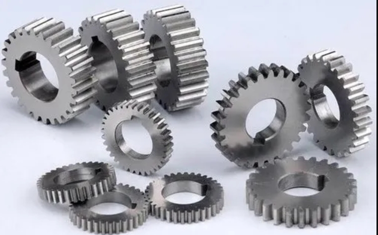
To begin, let me outline the methodology used for the spur gear analysis. The TCA model is established based on the geometry of the spur gear pair, considering parameters such as module, number of teeth, pressure angle, and tooth profile modifications. The LTCA model extends this by incorporating the effects of applied loads, allowing for the simulation of real-world operating conditions. For this study, I consider a spur gear pair from an航空 engine transmission, with detailed parameters listed in Table 1. The material properties are also provided, as they play a crucial role in stress calculations. The spur gear pair consists of a pinion (active gear) and a gear (passive gear), both made of 12Cr2Ni4A alloy steel, which is commonly used in high-stress applications due to its excellent mechanical properties.
| Gear Parameters | Pinion (Active Spur Gear) | Gear (Passive Spur Gear) |
|---|---|---|
| Module m (mm) | 3 | 3 |
| Number of Teeth z | 34 | 41 |
| Pressure Angle α (°) | 20 | 20 |
| Addendum (mm) | 3 | 3 |
| Dedendum (mm) | 2.08 | 2.13 |
| Face Width (mm) | 15 | 16 |
| Modification Coefficient (mm) | 0 | 0 |
| Rack Tool Fillet Radius (mm) | 0.9 | 0.9 |
| Rated Torque (N·m) | 82 | |
| Rated Speed (r/min) | 5,660 | 4,700 (derived from gear ratio) |
The material properties for the spur gear pair are essential for stress analysis. The 12Cr2Ni4A alloy steel has a density of 7.84 g/cm³ and an elastic modulus of 195 GPa. These values are used in the LTCA simulations to account for material deformation under load. The spur gear analysis begins with the TCA, which determines the geometric transmission error and contact patterns without load. This is followed by LTCA, which引入s the applied torque to compute the loaded transmission error, load distribution along the tooth face, and load sharing between multiple tooth pairs. The results from these simulations provide insights into the啮合 behavior of the spur gear pair, which are then used for strength calculations.
The TCA results for the spur gear pair show the contact印痕 and geometric transmission error. Under no-load conditions, the contact pattern indicates the areas of tooth engagement, which are critical for assessing alignment and potential stress concentrations. For this spur gear pair, the contact印痕 is relatively uniform, suggesting good manufacturing quality. The geometric transmission error, which represents the deviation from ideal motion transfer, is minimal, indicating that the spur gears are well-designed for smooth operation. However, under load, these characteristics change due to tooth deflection and contact deformation, which are captured by LTCA.
Next, I proceed to the LTCA simulations. The loaded transmission error for the spur gear pair is computed, showing how the error varies with the啮合 position under the applied torque of 82 N·m. This error is influenced by tooth stiffness and load distribution. The load distribution along the tooth face is also analyzed, revealing how the contact pressure varies across the tooth width. For spur gears, this distribution is typically uniform if the gears are perfectly aligned, but in practice, misalignments can cause edge loading. In this case, the LTCA results indicate a relatively even load distribution, thanks to the proper design of the spur gear pair. Additionally, the load sharing between tooth pairs is evaluated, as multiple teeth may be in contact simultaneously during meshing. The load sharing coefficient, defined as the ratio of load on a tooth pair to the total load, is calculated and shown to vary with the啮合 cycle. This information is crucial for understanding the dynamic loading on spur gears.
Based on the LTCA results, I compute the contact stresses and bending stresses for the spur gear pair. The contact stress calculation employs the Hertzian contact theory, which models the stress between two curved surfaces. For spur gears, the contact stress at each啮合 point can be expressed as:
$$ \sigma_c = \sqrt{\frac{F}{\pi \cdot \left(\frac{1-\nu_1^2}{E_1} + \frac{1-\nu_2^2}{E_2}\right) \cdot \frac{1}{R}}} $$
where \( \sigma_c \) is the contact stress, \( F \) is the normal load per unit width, \( \nu_1 \) and \( \nu_2 \) are Poisson’s ratios, \( E_1 \) and \( E_2 \) are elastic moduli, and \( R \) is the effective radius of curvature. For the spur gear pair, I use the material properties from Table 2, assuming Poisson’s ratio of 0.3 for both gears. The normal load is derived from the LTCA load distribution results. The computed contact stresses over the啮合 cycle are plotted, showing peaks at the points of maximum load. The maximum contact stress for this spur gear pair is found to be 641.4894 MPa, which occurs near the pitch point where the contact radius is smallest.
| Property | Value |
|---|---|
| Density (g/cm³) | 7.84 |
| Elastic Modulus (GPa) | 195 |
| Poisson’s Ratio (assumed) | 0.3 |
| Tensile Strength σ_b (MPa) | 1,100 |
| Bending Fatigue Limit σ_{-1} (MPa) | 519 |
| Contact Fatigue Limit σ_H (MPa) | 2,600 |
For bending stress analysis, I use the finite element stress influence matrix method. This approach involves creating a stress influence matrix through finite element analysis of a single tooth under unit load, and then superimposing the loads from LTCA to compute the bending stress distribution over the啮合 cycle. The bending stress at the tooth root is critical for assessing fatigue life, as it can lead to tooth breakage. The maximum bending stress for the pinion spur gear is 109.1514 MPa, and for the gear spur gear, it is 81.2704 MPa. These stresses are calculated at the critical section where the tooth fillet meets the root. The variation of bending stress over the啮合 cycle is analyzed, showing how the stress peaks when the tooth is fully loaded. This analysis is vital for understanding the fatigue behavior of spur gears under cyclic loading.
To further elaborate, the bending stress calculation involves determining the stress concentration factors due to the tooth geometry. For spur gears, the Lewis formula provides a basic estimate, but for accuracy, I use the following refined equation based on elastic theory:
$$ \sigma_b = \frac{F_t}{b \cdot m \cdot Y} \cdot K_a \cdot K_v \cdot K_m $$
where \( \sigma_b \) is the bending stress, \( F_t \) is the tangential load, \( b \) is the face width, \( m \) is the module, \( Y \) is the tooth form factor, and \( K_a \), \( K_v \), and \( K_m \) are application, dynamic, and load distribution factors, respectively. For the spur gear pair, these factors are derived from the LTCA results. The tooth form factor \( Y \) accounts for the tooth profile and is obtained from standard tables for spur gears. The computed bending stresses are then compared to the material’s fatigue limit to assess safety.
Moving on to fatigue life estimation, I propose an approximate method based on the LTCA results. The spur gear teeth undergo cyclic loading during operation, with stresses varying from zero to a maximum value. This pattern resembles a pulsating cycle, where the stress ratio \( R = \sigma_{\text{min}} / \sigma_{\text{max}} = 0 \). For bending stress, the maximum stress \( \sigma_{\text{max}} \) is the peak bending stress from LTCA, and the minimum stress \( \sigma_{\text{min}} \) is zero. The mean stress \( \sigma_m \) and stress amplitude \( \sigma_a \) are calculated as:
$$ \sigma_m = \frac{\sigma_{\text{max}} + \sigma_{\text{min}}}{2} = \frac{\sigma_{\text{max}}}{2} $$
$$ \sigma_a = \frac{\sigma_{\text{max}} – \sigma_{\text{min}}}{2} = \frac{\sigma_{\text{max}}}{2} $$
For the spur gear pair, the mean and amplitude stresses for bending are shown in Table 3. However, material fatigue data, such as S-N curves, are typically obtained under symmetric cycling (R = -1). To relate the pulsating cycle to symmetric cycling, I use the Goodman line, which is expressed as:
$$ \frac{\sigma_a}{\sigma_{-1N}} + \frac{\sigma_m}{\sigma_b} = 1 $$
where \( \sigma_{-1N} \) is the equivalent stress amplitude under symmetric cycling, and \( \sigma_b \) is the tensile strength of the material. Rearranging, the equivalent stress amplitude is:
$$ \sigma_{-1N} = \frac{\sigma_a \cdot \sigma_b}{\sigma_b – \sigma_m} $$
For the spur gear pair, I compute \( \sigma_{-1N} \) for both the pinion and gear. Then, applying a safety factor [n] of 1.6 (selected for high reliability in航空 applications), the design stress amplitude \( \sigma_{-1Ng} \) is:
$$ \sigma_{-1Ng} = [n] \cdot \sigma_{-1N} $$
The results are summarized in Table 3. For contact stress, the S-N curve is inherently based on pulsating cycling, so no conversion is needed. The maximum contact stress is directly compared to the contact fatigue limit.
| Parameter | Pinion Spur Gear | Gear Spur Gear |
|---|---|---|
| Max Bending Stress σ_rmax (MPa) | 109.1514 | 81.2704 |
| Mean Stress σ_m (MPa) | 54.5757 | 40.6352 |
| Stress Amplitude σ_a (MPa) | 54.5757 | 40.6352 |
| Equivalent Stress Amplitude σ_{-1N} (MPa) | 57.4248 | 42.1939 |
| Design Stress Amplitude σ_{-1Ng} (MPa) ([n]=1.6) | 91.8797 | 67.5102 |
| Bending Fatigue Limit σ_{-1} (MPa) | 519 | |
| Max Contact Stress σ_cmax (MPa) | 641.4894 | |
| Contact Fatigue Limit σ_H (MPa) | 2,600 | |
From Table 3, it is evident that the design stress amplitudes for bending (91.8797 MPa for the pinion and 67.5102 MPa for the gear) are significantly lower than the bending fatigue limit of 519 MPa. Similarly, the maximum contact stress of 641.4894 MPa is well below the contact fatigue limit of 2,600 MPa. Therefore, for this spur gear pair, both bending and contact fatigue lives can be considered infinite under the given operating conditions. This conclusion is based on the assumption that the spur gears are properly lubricated and free from manufacturing defects, which is typical for high-quality航空 components.
To deepen the analysis, I explore the factors influencing spur gear performance. The accuracy of TCA and LTCA depends heavily on the input parameters, such as tooth profile modifications. For spur gears, modifications like tip relief or root relief can reduce stress concentrations and improve load distribution. In this study, the spur gear pair has no modifications, but in practice, slight modifications are often applied to compensate for manufacturing errors and deflections. Additionally, the material properties play a crucial role; the 12Cr2Ni4A alloy steel offers high strength and good fatigue resistance, making it suitable for spur gears in demanding applications. The spur gear design also considers factors like module selection, which affects tooth size and load capacity. A larger module generally increases strength but may reduce smoothness of operation.
Furthermore, the啮合 process of spur gears involves dynamic effects that are not fully captured by static LTCA. However, for the purpose of strength calculation, static analysis provides a conservative estimate. In reality, spur gears may experience vibrations and impact loads, which can increase stresses. Therefore, the safety factor of 1.6 is applied to account for such uncertainties. The spur gear life calculation method presented here is approximate but effective for initial design assessments. For more precise life prediction, fatigue analysis using cumulative damage models like Miner’s rule can be employed, but that is beyond the scope of this article.
In conclusion, the comprehensive analysis of spur gear load contact and strength reveals several key insights. Through TCA and LTCA, I simulated the啮合 behavior of a spur gear pair under load, obtaining detailed results on contact patterns, transmission errors, and load distributions. The stress calculations showed that the maximum contact and bending stresses are within safe limits compared to the material’s fatigue strengths. The proposed fatigue life estimation method, based on Goodman’s line and S-N curves, indicates that the spur gear pair has an infinite fatigue life under the specified conditions. This outcome underscores the robustness of the spur gear design and the effectiveness of advanced analysis tools in gear engineering. Future work could involve exploring dynamic analyses or investigating the effects of different tooth modifications on spur gear performance. Overall, this study contributes to the ongoing efforts to optimize spur gear systems for reliability and efficiency in mechanical传动 applications.
To summarize, the use of TCA and LTCA for spur gear analysis provides a powerful means to predict performance and prevent failures. The integration of stress calculations and fatigue life estimation offers a holistic approach to spur gear design. As spur gears continue to be widely used in various industries, such analyses are essential for advancing gear technology. I hope this detailed exposition serves as a valuable resource for engineers and researchers working with spur gears. The methods and results presented here can be adapted to other spur gear configurations, fostering innovation in gear design and manufacturing.