
Gear transmissions are the backbone of modern machinery, responsible for transmitting power and motion between rotating shafts. Among various gear types, the spur gear remains one of the most fundamental and widely used due to its simplicity in design and manufacture. However, the dynamic interactions during meshing inevitably generate vibrations and noise, which can lead to accelerated wear, fatigue failure, and reduced system reliability. A critical factor in gear design is the management of contact stresses on the tooth flanks, as excessive stress is a primary cause of pitting and spalling failures. This analysis delves into the dynamic behavior of a meshing spur gear pair under oscillatory loads, employing Harmonic Response Analysis within a finite element framework. The core objective is to systematically investigate how vibrational excitations at different frequencies influence the contact stress response and deformation of the gear teeth, thereby providing insights crucial for designing quieter and more durable spur gear transmissions.
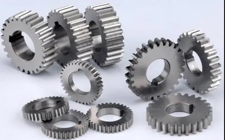
Harmonic response analysis is a specialized technique used to determine the steady-state behavior of a linear structure when subjected to continuous sinusoidal (harmonic) loading. Unlike transient analysis which looks at responses over a broad time range, harmonic analysis reveals how structures behave as a function of the excitation frequency. This is paramount for spur gear systems, as they are perpetually subjected to excitations whose frequencies are integer multiples of the shaft rotational speed (mesh frequency and its harmonics). The response variables of utmost interest are the dynamic contact stress and the resultant deformations, as these directly correlate with fatigue life and transmission error. This study simplifies the complex, time-varying meshing process by analyzing a quasi-static, yet critically loaded, single-tooth-pair contact position. This approach allows for a focused frequency-domain investigation into the system’s susceptibility to resonant amplification of stress, which is often the root cause of premature gear failure.
Theoretical Foundation: Dynamic Modeling of a Spur Gear Pair
To accurately simulate the dynamic response, a representative lumped-parameter model of a two-stage spur gear system is established. The model accounts for the torsional and translational degrees of freedom, as well as the time-varying mesh stiffness and damping. The gear pair is supported by bearings, which are modeled as linear springs and dampers in the horizontal (x) and vertical (y) directions. The meshing action between the pinion (driver) and gear (driven) is represented by a spring-damper element acting along the line of action, incorporating the essential spur gear contact mechanics.
The generalized coordinate vector for the 6-degree-of-freedom system is defined as:
$$ \mathbf{\delta} = \{ x_p, y_p, \theta_p, x_g, y_g, \theta_g \}^T $$
where \( x_p, y_p \) are the translational displacements of the pinion center, \( \theta_p \) is its rotational displacement, and \( x_g, y_g, \theta_g \) are the corresponding displacements for the gear. The equation of motion for this damped, forced vibration system is derived using Newton’s second law or Lagrange’s equations, resulting in the standard matrix form:
$$ \mathbf{[M] \{\ddot{\delta}\} + [C] \{\dot{\delta}\} + [K] \{\delta\} = \{F(t)\}} $$
Here, \( \mathbf{[M]} \), \( \mathbf{[C]} \), and \( \mathbf{[K]} \) are the mass, damping, and stiffness matrices, respectively. \( \mathbf{\{F(t)\}} \) is the harmonic force vector. For a spur gear pair, the stiffness matrix \( \mathbf{[K]} \) is particularly important as it contains the time-varying mesh stiffness \( k_m(t) \), which fluctuates as the number of tooth pairs in contact changes (from one to two and back). For harmonic analysis focused on a specific engagement point, \( k_m \) can be treated as a constant value corresponding to the single-pair contact stiffness. The damping matrix \( \mathbf{[C]} \) includes contributions from structural damping in the bearings (\( c_{x}, c_{y} \)) and the phenomenological mesh damping \( c_m \). The excitation force originates from the input torque applied to the pinion, which, when transformed to the line of action, acts as a harmonic force on the system.
The key parameters for the spur gear model used in this simulation are summarized in the table below:
| Parameter | Symbol | Pinion (Driver) | Gear (Driven) |
|---|---|---|---|
| Number of Teeth | \( Z \) | 17 | 34 |
| Module | \( m_n \) | 3 mm | |
| Pressure Angle | \( \alpha \) | 20° | |
| Face Width | \( b \) | 20 mm | |
| Pitch Diameter | \( d \) | 51 mm | 102 mm |
| Material | – | Structural Steel (Default) | |
The relationship between the input shaft speed \( n \) (in rpm) and the primary meshing excitation frequency \( f_m \) (in Hz) is given by:
$$ f_m = \frac{Z_1 \cdot n}{60} $$
For instance, a pinion rotating at 3000 rpm generates a fundamental mesh frequency of \( f_m = (17 \times 3000) / 60 = 850 \) Hz. Higher harmonics at \( 2f_m, 3f_m, \) etc., are also significant sources of excitation. The harmonic analysis in this work scans a frequency range from 0 Hz to 5000 Hz to capture potential resonant peaks within and beyond the typical operational range of a spur gear system.
Finite Element Model Development and Analysis Setup in Workbench
The three-dimensional geometry of the spur gear pair and its supporting shaft segments is created using CAD software, ensuring accurate tooth profiles based on the parameters listed above. The model is then imported into ANSYS Workbench for preprocessing. A critical step is defining the contact between the mating tooth flanks. A frictional contact formulation is employed with a coefficient of friction set to \( \mu = 0.1 \), which is a representative value for lubricated steel-on-steel contacts. This accounts for the tangential forces that influence the stress field, though the primary focus remains on the normal contact (Hertzian) stress. The support bearings are simulated by applying cylindrical support constraints on the shaft surfaces at the bearing locations (A, B, C, D), which restrict radial and axial movements while allowing free rotation—effectively modeling idealized rigid bearings. The material assigned is standard structural steel with the following default isotropic linear elastic properties:
| Property | Value |
|---|---|
| Young’s Modulus, \( E \) | 210 GPa |
| Poisson’s Ratio, \( \nu \) | 0.3 |
| Density, \( \rho \) | 7850 kg/m³ |
The finite element mesh is generated using tetrahedral elements with refinement in the contact region between the gear teeth to accurately capture the high stress gradients. The pinion shaft is designated as the input, where a moment (torque) of \( M = 200 \) N·m is applied as a harmonic force. In the Harmonic Response module, this moment is defined as a sinusoidal load with a specified amplitude, phase, and, most importantly, a sweeping frequency. The gear shaft is constrained as the output. The analysis is configured to solve for the system’s response (stress, strain, deformation) across the defined frequency spectrum. Initially, the damping is set to zero to identify the undamped natural frequencies and the theoretical maximum response. Subsequently, a more realistic constant damping ratio (\( \zeta \)) is introduced to evaluate its significant mitigating effect on the dynamic response. The modal superposition method is typically used for this type of linear harmonic analysis.
Analysis of Harmonic Response Results
The harmonic response analysis yields a frequency-dependent dataset for various output parameters. The primary results are examined in two key areas: the stress concentration at the pinion shaft fillet (a common location for bending fatigue failure) and the contact stress on the active tooth flanks of the spur gear pair.
1. Undamped System Response
With damping initially neglected (\(\zeta = 0\)), the analysis reveals the system’s theoretical resonant behavior. The plot of equivalent (von Mises) stress at the pinion shaft’s critical section versus excitation frequency shows a distinct and sharp peak. The maximum stress amplitude occurs at an excitation frequency of \( f = 3750 \) Hz. This frequency corresponds to one of the system’s natural frequencies where the input energy is most efficiently absorbed, leading to large amplitude vibrations and, consequently, very high dynamic stresses.
The phase relationship between the input harmonic torque on the pinion and the strain response on the gear provides insight into the system’s dynamic characteristics. As excitation frequency passes through resonance, a sharp 180-degree phase shift is observed, which is a classic indicator of resonant crossing in a single-degree-of-freedom system.
Most critically, the contact stress on the tooth flank at this resonant frequency (3750 Hz) reaches an extraordinarily high value. The maximum principal contact stress is calculated to be on the order of \( 1.09 \times 10^{10} \) Pa (10.9 GPa), which far exceeds the yield strength of any common gear steel. This result, while theoretically accurate for an undamped model, is physically unrealistic for a functioning spur gear. It starkly illustrates the catastrophic potential of operating at a resonant condition and underscores the necessity of damping and frequency management in design.
2. Damped System Response
To obtain a realistic prediction, material and structural damping must be incorporated. In engineering analysis, Rayleigh damping or a constant damping ratio is often used. For this study, a constant modal damping ratio of \( \zeta = 0.05 \) (5%) is applied, which is a reasonable estimate for assembled steel structures with joints and interfaces.
The inclusion of damping dramatically alters the response curves. The resonant peak in the pinion shaft stress versus frequency plot is still centered at the same natural frequency (~3750 Hz), confirming that damping affects the response amplitude but not the natural frequency itself in linear systems. However, the peak amplitude is now vastly reduced and the curve is broadened.
The corresponding maximum contact stress on the spur gear tooth flank at 3750 Hz drops to a value of approximately 79 MPa. This is a realistic, manageable stress level for a spur gear under a 200 N·m load. The comparison between the undamped and damped contact stress results highlights the paramount importance of accurately characterizing and incorporating damping in dynamic simulations. The results are summarized below:
| Condition | Resonant Frequency | Max Pinion Shaft Stress (at resonance) | Max Gear Contact Stress (at resonance) | Remarks |
|---|---|---|---|---|
| Undamped (\(\zeta = 0\)) | 3750 Hz | Extremely High | ~10.9 GPa | Theoretical, non-physical peak |
| Damped (\(\zeta = 0.05\)) | 3750 Hz | Significantly Reduced | ~79 MPa | Realistic, operational stress level |
Discussion and Practical Implications for Spur Gear Design
The harmonic response analysis conducted provides several key takeaways for the design and analysis of spur gear systems:
1. Identification of Critical Frequencies: The analysis successfully pinpoints the natural frequency of the system (3750 Hz in this model). For the example spur gear with 17 teeth, this resonant frequency would be excited when the pinion speed is approximately:
$$ n = \frac{60 \cdot f}{Z_1} = \frac{60 \times 3750}{17} \approx 13235 \text{ rpm} $$
Operating at or near this speed should be avoided to prevent resonant stress amplification. Design modifications, such as changing the mass or stiffness, can be explored to shift this critical frequency away from the operating range.
2. The Paramount Role of Damping: The contrast between damped and undamped results cannot be overstated. Damping is the primary mechanism that limits vibration amplitude at resonance. The accuracy of the damping parameter (\(\zeta\)) is therefore critical for obtaining reliable predictive results from harmonic analysis. This damping arises from material hysteresis, friction at meshing interfaces and bearings, and energy dissipation through the housing and lubricant. For precise simulations, experimental modal analysis is often required to determine the actual damping ratios of the assembled spur gear system.
3. Contact Stress as a Dynamic Variable: The study confirms that the maximum contact stress on a spur gear is not a static value but is highly dependent on the dynamic excitation. Even under a constant torque load, dynamic amplification can significantly increase the stress if the excitation frequency coincides with a structural mode. The classic Hertzian contact stress formula,
$$ \sigma_H = \sqrt{\frac{F_t / b}{2 \pi (1-\nu^2)} \cdot \frac{1/\rho_1 + 1/\rho_2}{1/E_1 + 1/E_2}} $$
where \( F_t \) is the normal tooth load, \( \rho \) are radii of curvature, provides the static baseline. The dynamic analysis yields a multiplier or a frequency response function for this stress.
4. Methodology for Dynamic Assessment: The presented approach—using a static, loaded contact position as a baseline for a frequency sweep—offers a computationally efficient method for an initial dynamic assessment of a spur gear design. It is particularly useful in the early design stages to check for potential resonances. For a full dynamic simulation including the effects of time-varying mesh stiffness, transmission error excitation, and multi-tooth contact, a transient dynamic analysis would be necessary. However, the harmonic response provides clear, frequency-domain insights that are complementary and often easier to interpret for identifying critical speeds.
Conclusion
This detailed investigation into the harmonic response of a meshing spur gear pair elucidates the profound influence of oscillatory loading frequency on the system’s dynamic stress state. By leveraging finite element-based harmonic analysis, it was demonstrated that the contact stress on the tooth flanks and the bending stress in the shaft are strongly amplified when the excitation frequency aligns with a structural natural frequency of the system. The initial analysis neglecting damping yielded non-physically high stresses, highlighting a purely theoretical worst-case resonant scenario. The subsequent incorporation of a realistic damping ratio dramatically reduced the response amplitudes to plausible operational levels, underscoring the critical importance of accurate damping characterization in any dynamic simulation of a spur gear train.
The findings emphasize that robust spur gear design must extend beyond static load capacity calculations. A dynamic assessment, including harmonic or modal analysis, is essential to identify and avoid resonant conditions that can lead to accelerated fatigue and failure. Key design strategies informed by such analysis include:
1. Detuning the system by altering mass or stiffness to shift natural frequencies away from operating mesh frequencies and their harmonics.
2. Incorporating or enhancing damping through material selection, composite structures, or specialized damping treatments.
3. Using the dynamic stress results from analyses like this one to perform more accurate fatigue life predictions.
In summary, harmonic response analysis serves as a powerful tool in the dynamic toolbox for spur gear design. It provides a clear frequency-domain map of the system’s vulnerability, guiding engineers toward designs that are not only strong but also dynamically stable, leading to longer life, lower noise, and more reliable power transmission.