
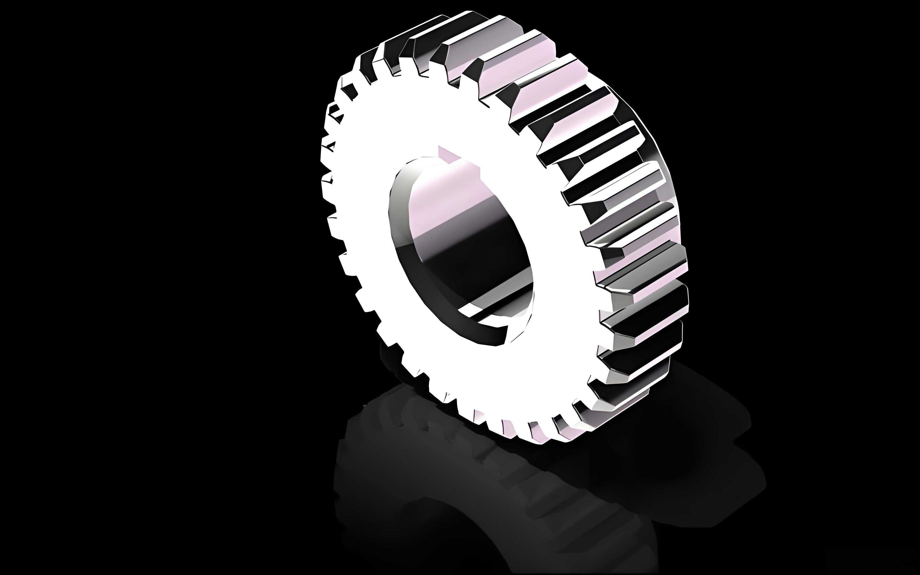
The design and modeling of spur gears constitute a fundamental task in mechanical engineering. The pursuit of automation in this process is driven by the need for accuracy, efficiency, and consistency, especially when generating families of parts with varying parameters. This article explores a robust methodology for the fully automated three-dimensional modeling of standard involute spur gears. The core of this approach lies in the precise mathematical definition of the involute curve, implemented within a modern parametric CAD environment using its built-in programming and relation tools. This method transcends common limitations, providing a single, universally applicable model capable of generating accurate spur gear geometry regardless of the number of teeth.
Fundamental Theory of the Involute Tooth Profile
The involute curve is the defining geometric feature of the modern spur gear tooth. Its unique property of ensuring constant angular velocity ratio during meshing makes it indispensable. Mathematically, an involute can be described as the path traced by a point on a taut string as it unwinds from a base circle. For a standard spur gear, the key parameters are the module (m), the number of teeth (z), and the pressure angle (α), typically 20°.
First, we define the critical diameters of the spur gear:
$$ d = m \cdot z \quad \text{(Pitch Diameter)} $$
$$ d_a = m \cdot (z + 2) \quad \text{(Addendum/Outside Diameter)} $$
$$ d_f = m \cdot (z – 2.5) \quad \text{(Dedendum/Root Diameter)} $$
$$ d_b = m \cdot z \cdot \cos(\alpha) = d \cdot \cos(\alpha) \quad \text{(Base Circle Diameter)} $$
The geometry of the involute for a spur gear is derived from the base circle. Let \( r_b = d_b / 2 \) be the base circle radius. Consider a point \( M \) on the involute curve at a radius \( r_y \) from the gear center \( O \). The pressure angle at point \( M \) is \( \alpha_y \). The fundamental relationship governing the involute spur gear profile is:
$$ \cos(\alpha_y) = \frac{r_b}{r_y} $$
The involute function, \( \text{inv}(\alpha) \), is central to the coordinate calculation:
$$ \text{inv}(\alpha) = \tan(\alpha) – \alpha \quad \text{(with α in radians)} $$
For a standard spur gear with zero profile shift (x=0) and no tooth thinning, the roll angle \( \eta_y \) for point M, measured from the line connecting the gear center to the starting point of the involute on the base circle, is given by:
$$ \eta_y = \frac{\pi}{2z} + \text{inv}(\alpha_y) – \text{inv}(\alpha) $$
Finally, placing the coordinate origin at the gear center and aligning the tooth space symmetry axis with the Y-axis, the Cartesian coordinates (x, y) of point M on the spur gear tooth flank are:
$$ x = r_y \cdot \sin(\eta_y) $$
$$ y = r_y \cdot \cos(\eta_y) $$
These equations form the precise mathematical model for generating the spur gear tooth profile. The variable \( r_y \) must range from the base circle radius \( r_b \) to the tip of the tooth. A critical insight for robust automation is that the generation must always start from the base circle \( r_b \), not the root circle \( r_f \). This is because for spur gears with a low number of teeth (typically z ≤ 41), the root circle is smaller than the base circle \( (d_f < d_b) \), making the equation \( \alpha_y = \arccos(r_b / r_y) \) invalid for \( r_y < r_b \). Starting from \( r_b \) guarantees a valid, continuous involute curve for any standard spur gear.
Implementation Strategy for Automated Spur Gear Modeling
The practical implementation leverages the parametric and programmable capabilities of advanced CAD software (exemplified here by Pro/ENGINEER or Creo Parametric). The goal is to create a single, intelligent model that rebuilds into any specified standard spur gear upon input of the core parameters.
1. Parameter Initialization and Relations
The first step is to declare the driving parameters and establish the mathematical relationships between them. This is done using the software’s Program and Relations tools.
Input Parameters: The model prompts the user for four fundamental values needed to define the spur gear.
| Parameter Symbol | Prompt Description | Variable Name Example |
|---|---|---|
| m | Module of the spur gear | MODULE |
| α | Pressure Angle (e.g., 20) | PRESSURE_ANGLE |
| z | Number of Teeth | NUM_TEETH |
| B | Face Width / Thickness | THICKNESS |
Defined Relations: Subsequently, the dependent geometric dimensions are automatically calculated via relations. These formulas are stored within the model and update dynamically.
| Calculated Dimension | Relation (Using Example Variables) | Mathematical Formula |
|---|---|---|
| Root Diameter | DEDENDUM_DIA = MODULE * (NUM_TEETH – 2.5) | $$ d_f = m(z – 2.5) $$ |
| Base Diameter | BASE_DIA = MODULE * NUM_TEETH * cos(PRESSURE_ANGLE) | $$ d_b = m z \cos(\alpha) $$ |
| Pitch Diameter | PITCH_DIA = MODULE * NUM_TEETH | $$ d = m z $$ |
| Addendum Diameter | ADDENDUM_DIA = MODULE * (NUM_TEETH + 2) | $$ d_a = m(z + 2) $$ |
2. Precise Involute Curve Creation via Datum Curve
The heart of the spur gear model is the exact involute profile. This is achieved by creating a datum curve defined by an equation. The equation editor uses a parameter ‘t’ which varies from 0 to 1. The radius \( r_y \) is defined to sweep from the base circle to a point slightly beyond the addendum circle (e.g., 1.2 times the addendum radius) to ensure the curve is long enough for subsequent trimming operations.
The equation written in the software’s syntax would be:
/* Define conversion constants */
torad = PI / 180
toang = 180 / PI
/* Get base radius from previously calculated diameter */
rb = BASE_DIA / 2
/* Define ry to vary from base radius to 1.2*addendum radius */
ry = ( (1.2 * ADDENDUM_DIA / 2) - rb ) * t + rb
/* Calculate the local pressure angle */
ay = acos( rb / ry )
/* Calculate the roll angle eta_y for a standard spur gear (x=0) */
/* Note: PI/(2*z) is the half-tooth-space angle on the base circle */
fy = ( PI / (2 * NUM_TEETH) ) + ( tan(ay) - ay ) - ( tan(20*torad) - 20*torad )
/* Cartesian coordinates of the involute point */
x = ry * sin( fy * toang )
y = ry * cos( fy * toang )
z = 0
This code block generates one flank of a single spur gear tooth. The mirroring of this curve about the tooth centerline creates the full, symmetric tooth space profile.
3. Solid Model Construction
The 3D spur gear solid is built in a sequential, feature-based manner:
Step 1 – Gear Blank: A cylindrical protrusion is created with a diameter equal to the root diameter \( d_f \) and a thickness equal to the input face width B. This forms the gear’s core.
Step 2 – Tooth Profile Sketch: In a new sketch for the tooth extrusion, reference circles are drawn for the root, base, pitch, and addendum circles. Their diameters are controlled by the previously defined relations (DEDENDUM_DIA, BASE_DIA, etc.). The generated involute curve and its mirror are used to define the tooth flanks.
Step 3 – Completing the Tooth Root: A crucial step for universal applicability. Since the involute for the spur gear starts at the base circle, the gap between the involute endpoint and the root circle must be filled with a fillet. For a standard spur gear, the root fillet radius is approximately \( 0.38m \). This fillet smoothly connects the active tooth profile to the root diameter, correctly handling both cases where \( d_f < d_b \) and \( d_f > d_b \). This fillet radius should also be defined as a relation (e.g., ROOT_FILLET = 0.38 * MODULE).
Step 4 – Pattern Generation: A single extruded tooth is created. This tooth is then patterned circularly around the gear axis. The number of instances in this pattern is driven by the parameter NUM_TEETH, and the angular increment is \( 360 / \text{NUM\_TEETH} \) degrees. This relation ensures the tooth count updates automatically when the spur gear is regenerated with new parameters.
Summary of the Automated Design Process
The entire workflow for creating an automated spur gear model can be summarized in the following table, which outlines the sequence, the tool used, and the critical logic or relation established at each stage.
| Stage | CAD Feature/Tool | Key Action & Logic | Driving Parameter/Relation |
|---|---|---|---|
| 1. Input | Program (Input Section) | Declare primary spur gear parameters. | MODULE, PRESSURE_ANGLE, NUM_TEETH, THICKNESS |
| 2. Calculation | Relations | Compute all dependent diameters. | DEDENDUM_DIA = m*(z-2.5), BASE_DIA = m*z*cos(α), etc. |
| 3. Curve Gen. | Datum Curve (From Equation) | Define the involute from \( r_b \) to ~1.2*\( r_a \). | $$ \begin{aligned} r_y(t) &= … \\ x &= r_y \sin(\eta_y) \\ y &= r_y \cos(\eta_y) \end{aligned} $$ |
| 4. Solid Base | Extrude | Create cylinder with root diameter. | Diameter = DEDENDUM_DIA, Depth = THICKNESS |
| 5. Tooth Sketch | Sketch (Use Edge, Fillet) | Project involutes, close with root fillet. | Fillet Radius = 0.38 * MODULE |
| 6. First Tooth | Extrude | Protrude the sketched tooth profile. | Depth = THICKNESS |
| 7. Full Gear | Pattern (Axis) | Circular pattern of the first tooth. | Instances = NUM_TEETH, Angle = 360 / NUM_TEETH |
Advantages and Applications of the Automated Spur Gear Model
The methodology described offers significant benefits over manual or template-based spur gear modeling:
1. Universal Applicability: This is the most salient advantage. By generating the involute curve starting strictly from the base circle, a single model file can accurately produce any standard involute spur gear, from a pinion with very few teeth to a large gear with many teeth, without requiring separate logic or model templates for different regimes.
2. Parametric Flexibility and Accuracy: The model is driven by the fundamental gear parameters (m, z, α). Changing any of these inputs triggers a full regeneration of an accurately calculated spur gear geometry. The use of the exact involute equation ensures mathematical precision, which is critical for analysis tasks like finite element analysis (FEA) or generating manufacturing data for gear hobbing.
3. Design Efficiency and Consistency: Automating the repetitive and complex task of tooth profile creation saves considerable time. It also eliminates human error in the geometric construction, ensuring that every generated spur gear in a product family is consistent and conforms to the standard.
4. Foundation for Advanced Development: This automated spur gear model serves as a perfect foundation for more complex tasks. It can be integrated into larger assembly automation routines, used for automated drawing generation with correct gear data tables, or extended to model modified spur gears (with profile shift), helical gears, bevel gears, or worm gears by building upon the core parametric and programmatic principles.
Conclusion
The automated design of standard involute spur gears is fully achievable by integrating precise mathematical formulations with the programmable features of modern CAD systems. The key to a robust implementation is the correct generation of the involute profile from the base circle radius upwards, coupled with a parameterized root fillet. This approach consolidates what might otherwise require multiple models into one intelligent, flexible, and universally applicable template. The resulting automated spur gear model enhances design accuracy, dramatically improves productivity, and ensures geometric consistency, forming a critical component in the digital toolkit for modern mechanical design and transmission system development. The principles outlined here for the spur gear provide a clear blueprint for automating the design of other standardized mechanical components governed by well-defined geometric rules.