
I focus on the tooth surface design of helical gears used in electric vehicle transmissions. Compared with conventional fuel vehicles, electric vehicles have the advantages of zero direct emissions, fast acceleration, and high driveline efficiency. However, the electric motor is often directly coupled with the reducer, and the peak input speed can reach 17900 r/min. This high speed, together with the requirement for low noise and long life, makes the geometric design and micro-modification of helical gears much more demanding. In my work, I study both the macro-geometric equal strength design and the micro tooth surface modification of helical gears. The main goal is to reduce the strength difference between the pinion and the gear, and to avoid edge contact caused by installation errors, so that the helical gear pair can operate smoothly and reliably.
In actual electric vehicle reducers, helical gears often adopt addendum modification, high-tooth profiles, and profile or lead modification. Traditional design methods usually only ensure that the gear pair meets the required working strength, but they often ignore the strength difference between the pinion and the gear. This can cause one member of the helical gear pair to fail earlier than the other, leading to premature failure of the whole reducer. In addition, installation errors, manufacturing errors, and elastic deformation can cause edge contact, stress concentration, and transmission error fluctuations. Therefore, I propose an integrated design method that combines equal strength optimization with tooth surface modification.
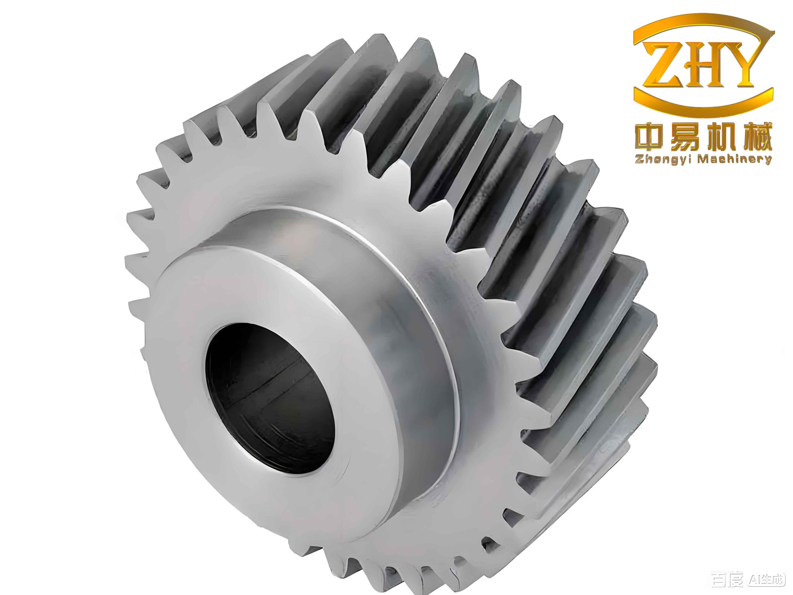
Tooth Surface Modeling of Helical Gears
I establish the tooth surface model of helical gears by using the rack cutter generation principle. The rack cutter is a basic tool for generating involute helical gears. By changing the addendum coefficient of the rack cutter and adjusting the relative position between the cutter and the gear blank, I can generate helical gears with modification and high teeth. For the pinion and the gear, I define moving coordinate systems \(S_{ci}\), \(S_{ni}\), and \(S_{ki}\), where \(i=1,2\) represents the pinion and the gear, respectively. The coordinate system \(S_i\) is fixed to the gear, and \(S_{di}\) and \(S_{fi}\) are auxiliary coordinate systems fixed to the frame. The rotation angle is \(\phi_i\), the pitch radius is \(r_i\), the rack cutter displacement is \(r_i \phi_i\), the modification coefficient is \(x_n\), the normal module is \(m_n\), and the helix angle is \(\beta\).
The normal end-face profile of the rack cutter used to generate the pinion and the gear is defined. The position vector of the rack cutter tooth surface in coordinate system \(S_{ki}\) can be written as
$$
\mathbf{R}_{ki}(u_i,l_i) = \begin{bmatrix} u_i \\ l_i \\ 0 \\ 1 \end{bmatrix}
$$
where \(u_i\) and \(l_i\) are two independent parameters of the rack cutter tooth surface. The position vector in \(S_{ni}\) is obtained by the coordinate transformation
$$
\mathbf{R}_{ni}(u_i,l_i) = \mathbf{M}_{n_i k_i} \mathbf{R}_{ki}(u_i,l_i)
$$
The transformation matrix \(\mathbf{M}_{n_i k_i}\) is expressed as
$$
\mathbf{M}_{n_i k_i} =
\begin{bmatrix}
\cos\alpha_n & \sin\alpha_n & 0 & 0.25s \\
-\sin\alpha_n & \cos\alpha_n & 0 & 0 \\
0 & 0 & 1 & 0 \\
0 & 0 & 0 & 1
\end{bmatrix}
$$
where \(\alpha_n\) is the normal pressure angle and \(s\) is the pitch of the rack cutter at the reference line. The unit normal vector of the rack cutter end-face profile in \(S_{ki}\) is
$$
\mathbf{N}_{ki} = \frac{\partial \mathbf{R}_{ki}}{\partial u_i} \times \frac{\partial \mathbf{R}_{ki}}{\partial l_i}
$$
The tooth surfaces of the pinion and the gear, denoted by \(\Sigma_1\) and \(\Sigma_2\), are generated by the rack cutter surfaces \(\Sigma_{k1}\) and \(\Sigma_{k2}\). The position vector and unit normal vector of the theoretical tooth surface in \(S_i\) are obtained by coordinate transformation and the meshing equation. The position vector is
$$
\mathbf{R}_i(u_i,l_i,\phi_i) = \mathbf{M}_{i k_i} \mathbf{R}_{ki}(u_i,l_i)
$$
where \(\mathbf{M}_{i k_i}\) is the \(4 \times 4\) coordinate transformation matrix from \(S_{ki}\) to \(S_i\), given by
$$
\mathbf{M}_{i k_i} = \mathbf{M}_{i f_i} \mathbf{M}_{f_i c_i} \mathbf{M}_{c_i n_i} \mathbf{M}_{n_i k_i}
$$
The individual transformation matrices are
$$
\mathbf{M}_{n_i k_i} =
\begin{bmatrix}
\cos\alpha_n & \sin\alpha_n & 0 & 0.25s \\
-\sin\alpha_n & \cos\alpha_n & 0 & 0 \\
0 & 0 & 1 & 0 \\
0 & 0 & 0 & 1
\end{bmatrix}
$$
$$
\mathbf{M}_{c_i n_i} =
\begin{bmatrix}
1 & 0 & 0 & 0 \\
0 & \cos\beta & \sin\beta & 0 \\
0 & -\sin\beta & \cos\beta & 0 \\
0 & 0 & 0 & 1
\end{bmatrix}
$$
$$
\mathbf{M}_{f_i c_i} =
\begin{bmatrix}
1 & 0 & 0 & r_i \phi_i \\
0 & 1 & 0 & r_i + x_n m_n \\
0 & 0 & 1 & 0 \\
0 & 0 & 0 & 1
\end{bmatrix}
$$
$$
\mathbf{M}_{i f_i} =
\begin{bmatrix}
\cos\phi_i & \sin\phi_i & 0 & 0 \\
-\sin\phi_i & \cos\phi_i & 0 & 0 \\
0 & 0 & 1 & 0 \\
0 & 0 & 0 & 1
\end{bmatrix}
$$
The rotation angle \(\phi_i\) is solved from the meshing equation
$$
\frac{X_i – x_i}{N_{xi}} = \frac{Y_i – y_i}{N_{yi}}
$$
which leads to
$$
\phi_i = \frac{R_{ciy} – x_n m_n – N_{cix} R_{cix}}{r_i N_{ciy}}
$$
where \(R_{cix}\) and \(R_{ciy}\) are the two coordinate components of the rack cutter position vector \(\mathbf{R}_{ci}\) in \(S_{ci}\), and \(N_{cix}\) and \(N_{ciy}\) are the two coordinate components of the unit normal vector \(\mathbf{N}_{ci}\) in \(S_{ci}\). The unit normal vector of the generated tooth surface is
$$
\mathbf{N}_i(u_i,l_i,\phi_i) = \mathbf{L}_{i k_i} \mathbf{N}_{ki}(u_i,l_i)
$$
where \(\mathbf{L}_{i k_i}\) is obtained by removing the fourth row and fourth column of \(\mathbf{M}_{i k_i}\).
To visualize the full tooth surface of helical gears, I discretize the tooth surface into a grid. The basic idea is to project points on the tooth surface onto a plane passing through the gear rotation axis, which is called the rotational projection plane or axial section. In this plane, I define a coordinate system where the \(X\)-axis coincides with the gear rotation axis. The projection plane grid is defined by \(m\) nodes along the tooth width direction and \(n\) nodes along the tooth height direction. The coordinates of the discrete points on the helical gear tooth surface in the rotational projection plane satisfy
$$
x_{i(kj)}^2 + y_{i(kj)}^2 = Y_{kj}, \quad z_{i(kj)} = X_{kj}
$$
where \([x_{i(kj)}, y_{i(kj)}, z_{i(kj)}]^T\) are the node coordinates in \(S_i\). Combining the tooth surface equation, the meshing equation, and the projection plane equation, I solve the nonlinear equations using a numerical solver to obtain the discrete point coordinates of the helical gear tooth surface.
Tooth Contact Analysis of Helical Gears
Tooth contact analysis (TCA) is a powerful tool for simulating the geometric contact of helical gears under unloaded or lightly loaded conditions. It can provide the contact position, contact pattern, and geometric transmission error, which are important indicators of meshing quality. I construct a TCA model for helical gears considering installation errors and edge contact. The coordinate system for the helical gear pair is defined as follows. The coordinate systems \(S_1\) and \(S_2\) are fixed to the pinion and the gear, respectively. The \(z_1\) and \(z_2\) axes are the rotation axes of the pinion and the gear without errors. The rotation angles are \(\phi_1\) and \(\phi_2\). The installation center distance is \(E\), the center distance error is \(\Delta E\), and the horizontal shaft angle error is \(\theta\). The two tooth surfaces are in contact in the frame coordinate system \(S_f\).
According to the continuous tangency condition, the two tooth surfaces must satisfy
$$
\mathbf{r}_f^{(1)} = \mathbf{r}_f^{(2)}, \quad \mathbf{n}_f^{(1)} = \mathbf{n}_f^{(2)}
$$
where \(\mathbf{r}_f^{(1)}\) and \(\mathbf{r}_f^{(2)}\) are the position vectors of the contact point on the two tooth surfaces in \(S_f\), and \(\mathbf{n}_f^{(1)}\) and \(\mathbf{n}_f^{(2)}\) are the corresponding unit normal vectors. In the presence of installation errors, the contact equations in \(S_f\) can be written as
$$
\mathbf{M}_{f1} \mathbf{R}_1(u_1,l_1,\phi_1) = \mathbf{M}_{f2} \mathbf{R}_2(u_2,l_2,\phi_2)
$$
$$
\mathbf{L}_{f1} \mathbf{n}_1(u_1,l_1,\phi_1) = \mathbf{L}_{f2} \mathbf{n}_2(u_2,l_2,\phi_2)
$$
where \(\mathbf{M}_{f1}\) and \(\mathbf{M}_{f2}\) are the coordinate transformation matrices from \(S_1\) to \(S_f\) and from \(S_2\) to \(S_f\), respectively, and \(\mathbf{L}_{f1}\) and \(\mathbf{L}_{f2}\) are the corresponding basis transformation matrices. The matrix \(\mathbf{M}_{f1}\) is
$$
\mathbf{M}_{f1} =
\begin{bmatrix}
\cos\phi_1 & \sin\phi_1 & 0 & 0 \\
-\sin\phi_1 & \cos\phi_1 & 0 & 0 \\
0 & 0 & 1 & 0 \\
0 & 0 & 0 & 1
\end{bmatrix}
$$
The matrix \(\mathbf{M}_{f2}\) is determined by
$$
\mathbf{M}_{f2} = \mathbf{M}_{fd} \mathbf{M}_{d2}
$$
where
$$
\mathbf{M}_{d2} =
\begin{bmatrix}
\cos\phi_2 \cos\theta & \sin\phi_2 \cos\theta & -\sin\theta & 0 \\
-\sin\phi_2 & \cos\phi_2 & 0 & 0 \\
\cos\phi_2 \sin\theta & \sin\phi_2 \sin\theta & \cos\theta & 0 \\
0 & 0 & 0 & 1
\end{bmatrix}
$$
$$
\mathbf{M}_{fd} =
\begin{bmatrix}
1 & 0 & 0 & 0 \\
0 & 1 & 0 & -E – \Delta E \\
0 & 0 & 1 & 0 \\
0 & 0 & 0 & 1
\end{bmatrix}
$$
Since the installation errors are known, the vector equation projects onto the \(x\), \(y\), and \(z\) axes. Because \(|\mathbf{n}_f^{(1)}| = |\mathbf{n}_f^{(2)}| = 1\), I obtain five independent algebraic equations with six unknowns \(u_1, l_1, u_2, l_2, \phi_1, \phi_2\). Taking the pinion rotation angle \(\phi_1\) as the input with a fixed step size, I can solve for the contact point parameters \((u_1,l_1)\), \((u_2,l_2)\), and \(\phi_2\) until the contact point exceeds the tooth surface boundary. All contact points form the contact path. The initial meshing point corresponds to the rotation angles \(\phi_{10}\) and \(\phi_{20}\). The relative rotation angles are
$$
\Delta\phi_1 = \phi_1 – \phi_{10}, \quad \Delta\phi_2 = \phi_2 – \phi_{20}
$$
For a gear pair with a constant transmission ratio, the transmission function is linear, and the gear rotation angle should be \(\Delta\phi_2 = (z_1/z_2)\Delta\phi_1\). However, in actual transmission, the angular velocity ratio is not constant due to errors. The geometric transmission error is defined as
$$
GT = \phi_2 – \phi_{20} – \frac{z_1}{z_2}(\phi_1 – \phi_{10})
$$
Edge contact occurs when the helical gear pair is subjected to installation errors or manufacturing errors. During meshing in and meshing out, edge contact can cause angular velocity jumps and large vibration and noise. Edge contact mainly includes tooth side contact and tooth tip contact, which belong to line-surface contact. In this case, the conventional TCA algorithm is no longer applicable. According to the condition that the tangent line on the edge is perpendicular to the normal vector of the contact surface, when the pinion tooth side contacts the gear tooth surface, the pinion tooth surface parameter \(l_1\) is constant. The contact equation in \(S_f\) is
$$
\mathbf{M}_{f1} \mathbf{R}_1(u_1,l_1^*(u_1)) = \mathbf{M}_{f2} \mathbf{R}_2(u_2,l_2)
$$
$$
\frac{\partial \mathbf{R}_1}{\partial u_1} \cdot \mathbf{M}_{f1}^T \mathbf{L}_{f2} \mathbf{n}_2 = 0
$$
where \(\mathbf{R}_1(u_1,l_1^*(u_1))\) represents the tooth side of the pinion, and \(\partial \mathbf{R}_1 / \partial u_1\) is the tangent of the tooth side. When the pinion tooth tip contacts the gear tooth surface, the pinion tooth surface parameter \(u_1\) is constant. The contact equation is
$$
\mathbf{M}_{f1} \mathbf{R}_1(u_1^*(l_1),l_1) = \mathbf{M}_{f2} \mathbf{R}_2(u_2,l_2)
$$
$$
\frac{\partial \mathbf{R}_1}{\partial l_1} \cdot \mathbf{M}_{f1}^T \mathbf{L}_{f2} \mathbf{n}_2 = 0
$$
where \(\mathbf{R}_1(u_1^*(l_1),l_1)\) represents the tooth tip of the pinion, and \(\partial \mathbf{R}_1 / \partial l_1\) is the tangent of the tooth tip. These equations form nonlinear systems with four unknowns and four equations, which can be solved for a given input angle \(\phi_1\).
Principal Curvature Relation and Contact Ellipse
Assume that two surfaces \(\Sigma_1\) and \(\Sigma_2\) are in continuous tangency, and point \(P\) is their common tangent point. According to differential geometry, the curvatures along different tangent directions are different. The extreme values are the principal curvatures, and the corresponding tangent directions are the principal directions. Let \(k_f\) and \(k_h\) be the two principal curvatures of surface \(\Sigma_1\) at point \(P\), and let \(\mathbf{e}_f\) and \(\mathbf{e}_h\) be the corresponding principal directions. Let \(k_s\) and \(k_q\) be the two principal curvatures of surface \(\Sigma_2\) at point \(P\), and let \(\mathbf{e}_s\) and \(\mathbf{e}_q\) be the corresponding principal directions. Let \(\sigma^{(12)}\) be the angle from \(\mathbf{e}_f\) to \(\mathbf{e}_s\) measured counterclockwise. The relative velocity of point \(P\) with respect to surface \(i\) is \(\mathbf{v}_r^{(i)}\), and the relative velocity of the unit normal vector end with respect to surface \(i\) is \(\dot{\mathbf{v}}_r^{(i)}\). The angular velocities of the two surfaces are \(\boldsymbol{\omega}^{(1)}\) and \(\boldsymbol{\omega}^{(2)}\), and the relative angular velocity is \(\boldsymbol{\omega}^{(12)}\).
Using the Rodrigues formula and the gear meshing equation, I derive the linear equations for \(v_f^{(2)}\) and \(v_h^{(2)}\):
$$
\begin{bmatrix}
b_{11} & b_{12} \\
b_{21} & b_{22}
\end{bmatrix}
\begin{bmatrix}
v_f^{(2)} \\
v_h^{(2)}
\end{bmatrix}
=
\begin{bmatrix}
-b_{13} \\
-b_{23}
\end{bmatrix}
$$
where
$$
b_{11} = 0.5(k_f – k_s + k_h – k_q) + 0.5(k_f + k_h – k_s – k_q)\cos 2\sigma^{(12)}
$$
$$
b_{12} = b_{21} = 0.5(k_s – k_q)\sin 2\sigma^{(12)}
$$
$$
b_{13} = b_{31} = (k_h – k_f)\mathbf{e}_h \cdot \mathbf{v}^{(12)} – \mathbf{e}_f \cdot \boldsymbol{\omega}^{(12)}
$$
$$
b_{22} = 0.5(k_h – k_s + k_f – k_q) + 0.5(k_f + k_h – k_s – k_q)\cos 2\sigma^{(12)}
$$
$$
b_{23} = b_{32} = (k_f – k_h)\mathbf{e}_f \cdot \mathbf{v}^{(12)} – \mathbf{e}_h \cdot \boldsymbol{\omega}^{(12)}
$$
For helical gears, the tooth surfaces are in line contact. The solution of the linear system is not unique. The rank of the coefficient matrix and the augmented matrix is one, so
$$
b_{33} = \frac{b_{13}^2 + b_{23}^2}{b_{11} + b_{22}}
$$
When the principal curvatures and principal directions of surface \(\Sigma_1\) at point \(P\) are known, the principal curvatures and principal directions of surface \(\Sigma_2\) at point \(P\) can be determined by
$$
k_q + k_s = k_f + k_h – \frac{b_{13}^2 + b_{23}^2}{b_{33}}
$$
$$
k_q – k_s = \frac{\sqrt{(b_{13}^2 + b_{23}^2 – b_{33}(k_f – k_h))^2 + 4b_{33}^2 b_{12}^2}}{b_{33}}
$$
$$
\mathbf{e}_q = \mathbf{e}_f \cos\sigma^{(12)} + \mathbf{e}_h \sin\sigma^{(12)}
$$
$$
\mathbf{e}_s = -\mathbf{e}_f \sin\sigma^{(12)} + \mathbf{e}_h \cos\sigma^{(12)}
$$
The contact ellipse is formed by the elastic deformation of the tooth surfaces under load. The elastic deformation \(\delta\) is treated as a fixed value of \(0.00635\) mm in my TCA analysis. The semi-major axis \(a\) and semi-minor axis \(b\) of the contact ellipse are
$$
a = \sqrt{\frac{\delta}{A}}, \quad b = \sqrt{\frac{\delta}{B}}
$$
where
$$
A = \frac{1}{2}(K_\Sigma^{(1)} – K_\Sigma^{(2)}) – \frac{1}{4}\sqrt{g_1^2 + g_2^2 – 2g_1 g_2 \cos 2\sigma}
$$
$$
B = \frac{1}{2}(K_\Sigma^{(1)} – K_\Sigma^{(2)}) + \frac{1}{4}\sqrt{g_1^2 + g_2^2 – 2g_1 g_2 \cos 2\sigma}
$$
Here, \(K_\Sigma^{(1)} = k_1 + k_2\), \(K_\Sigma^{(2)} = k_3 + k_4\), \(g_1 = k_1 – k_2\), and \(g_2 = k_3 – k_4\). The angle between the major axis direction \(\boldsymbol{\eta}\) and \(\mathbf{e}_1\) is
$$
\alpha^{(1)} = \frac{1}{2}\arctan\left(\frac{g_2 \sin 2\sigma}{g_1 – g_2 \cos 2\sigma}\right)
$$
The unit vectors of the major and minor axes are
$$
\boldsymbol{\eta} = \mathbf{e}_1 \sin\alpha^{(1)} + \mathbf{e}_2 \cos\alpha^{(1)}
$$
$$
\boldsymbol{\zeta} = \mathbf{e}_1 \cos\alpha^{(1)} – \mathbf{e}_2 \sin\alpha^{(1)}
$$
Geometric Contact Analysis under Installation Errors
I use a two-stage reducer of an electric vehicle as an example. The high-speed stage helical gear pair has the following parameters: pinion tooth number \(z_1=19\), gear tooth number \(z_2=59\), normal module \(m_n=2.5\) mm, pressure angle \(20^\circ\), helix angle \(\beta=15.3^\circ\), tooth width \(b=30\) mm, addendum coefficient \(h_{an}^*=1.25\), clearance coefficient \(c_n^*=0.25\), pinion modification coefficient \(x_{n1}=0.101\), gear modification coefficient \(x_{n2}=-0.134\). The pinion is left-handed, and the gear is right-handed.
I establish the full tooth surface models of the pinion and the gear. The black grid area is the actual working tooth surface, and the red grid area is the transition surface. Based on the TCA model, I study the influence of center distance error and horizontal shaft angle error on the geometric contact characteristics of helical gears. When the center distance error is \(\Delta E = 0.02\) mm and the horizontal shaft angle error is \(\theta=0\), edge contact occurs at both ends of the tooth width. Because the involute profile has the property of center distance separability, a small center distance error does not change the transmission ratio, so the geometric transmission error should be zero. The small fluctuation in the TCA result is caused by the micro-modification of the tooth surface used to avoid infinite solutions in line contact. When the center distance error is \(\Delta E=0\) and the horizontal shaft angle error is \(\theta=0.2’\), severe edge contact occurs at one end of the tooth width, and the amplitude of the geometric transmission error increases. Therefore, the contact path of helical gears is sensitive to installation errors, and edge contact should be avoided to ensure good meshing quality.
Equal Strength Design of Helical Gear Transmission
The concept of equal strength design is to make the strength and life of each component as consistent as possible. For helical gears in electric vehicles, the working conditions are complex and the environment is severe. The traditional design method only satisfies the working strength requirement but ignores the strength difference between the pinion and the gear. This can cause the weaker gear to fail earlier, and the performance of the helical gear pair cannot be fully utilized. The main failure modes of helical gears are tooth root breakage and tooth surface pitting and wear. Tooth root breakage often occurs without warning and can cause huge economic losses and personal injury. Therefore, equal strength design should ensure that the maximum tooth root bending stress and tooth surface contact stress of the pinion and the gear are as equal as possible.
I calculate the tooth surface contact stress based on Hertzian stress. According to the standard and gear handbook, the contact stresses of the pinion and the gear are
$$
\sigma_{H1} = Z_B \sigma_{H0} \sqrt{K_A K_V K_{H\beta} K_{H\alpha}}
$$
$$
\sigma_{H2} = Z_D \sigma_{H0} \sqrt{K_A K_V K_{H\beta} K_{H\alpha}}
$$
where \(\sigma_{H1}\) and \(\sigma_{H2}\) are the calculated contact stresses of the pinion and the gear, \(Z_B\) and \(Z_D\) are the single pair tooth meshing coefficients of the pinion and the gear, \(K_A\) is the application factor, \(K_V\) is the dynamic factor, \(K_{H\beta}\) is the face load distribution factor for contact stress, and \(K_{H\alpha}\) is the transverse load distribution factor for contact stress. The basic value of contact stress at the pitch point is
$$
\sigma_{H0} = Z_H Z_E Z_\epsilon Z_\beta \sqrt{\frac{F_t}{d_1 b} \frac{u+1}{u}}
$$
where \(Z_H\) is the zone factor at the pitch point, \(Z_E\) is the elasticity factor, \(Z_\epsilon\) is the contact ratio factor, \(Z_\beta\) is the helix angle factor, \(d_1\) is the pitch diameter of the pinion, \(b\) is the tooth width, and \(u\) is the transmission ratio.
The tooth root bending stress is calculated as
$$
\sigma_{F1} = \sigma_{F01} K_A K_V K_{F\beta} K_{F\alpha}
$$
$$
\sigma_{F2} = \sigma_{F02} K_A K_V K_{F\beta} K_{F\alpha}
$$
where \(\sigma_{F1}\) and \(\sigma_{F2}\) are the calculated bending stresses of the pinion and the gear, \(K_{F\beta}\) is the face load distribution factor for bending stress, and \(K_{F\alpha}\) is the transverse load distribution factor for bending stress. The basic value of tooth root stress is
$$
\sigma_{F0} = \frac{F_t}{b m_n} Y_F Y_S Y_\beta
$$
where \(m_n\) is the normal module, \(Y_F\) is the form factor, \(Y_S\) is the stress correction factor, and \(Y_\beta\) is the helix angle factor.
I analyze a two-stage reducer of an electric vehicle. The input power is \(P=30\) kW, the maximum input torque is \(T=140\) N·m, and the application factor is \(K_A=1.25\). The pinion material is 20CrMnTi, carburized and quenched, with a surface hardness of HRC57–63. The gear material is 20Cr, carburized and quenched, with a surface hardness of HRC56–62. The elasticity factor is \(Z_E=189.8 \sqrt{\text{MPa}}\). The allowable contact stress is 1500 MPa, and the allowable bending stress is 400 MPa. The geometric parameters of the two-stage reducer are listed in Table 1.
| Geometric parameter | First stage | Second stage |
|---|---|---|
| Pinion tooth number \(z_1\) | 19 | 27 |
| Gear tooth number \(z_2\) | 59 | 87 |
| Normal module \(m_n\) / mm | 2.5 | 2 |
| Pressure angle \(\alpha_n\) / ° | 20 | 20 |
| Helix angle \(\beta\) / ° | 15.3 | 18.1 |
| Pinion tooth width \(b_1\) / mm | 30 | 33 |
| Gear tooth width \(b_2\) / mm | 30 | 33 |
| Addendum coefficient \(h_{an}^*\) | 1.25 | 1.2 |
| Clearance coefficient \(c_n^*\) | 0.25 | 0.25 |
| Root fillet radius \(\rho_f\) / mm | 0.75 | 0.6 |
| Pinion modification coefficient \(x_{n1}\) | 0.101 | 0.153 |
| Gear modification coefficient \(x_{n2}\) | -0.134 | -0.12 |
The static strength results are shown in Table 2. It can be seen that both the first stage and the second stage have relatively high contact stress, and there is a certain bending stress difference between the pinion and the gear in each stage. Therefore, optimization design is needed to reduce the tooth surface contact stress and improve the tooth surface contact strength, while narrowing the tooth root bending stress difference, so that the bending strength of the helical gear pair is as equal as possible.
| Parameter | First stage | Second stage |
|---|---|---|
| Tooth surface contact stress \(\sigma_H\) / MPa | 1005.441 | 1098.85 |
| Pinion root bending stress \(\sigma_{F1}\) / MPa | 197.653 | 213.54 |
| Gear root bending stress \(\sigma_{F2}\) / MPa | 146.93 | 186.59 |
Multi-Objective Optimization of Macro-Geometric Parameters
I take the high-speed stage helical gear pair as the research object. The design variables are the pinion tooth number \(z_1\), normal module \(m_n\), helix angle \(\beta\), pinion modification coefficient \(x_{n1}\), and gear modification coefficient \(x_{n2}\). The design variable vector is
$$
\mathbf{X} = [x_1, x_2, x_3, x_4, x_5]^T = [z_1, m_n, \beta, x_{n1}, x_{n2}]^T
$$
The first optimization objective is to minimize the tooth surface contact stress \(f_1\):
$$
\min f_1 = \sigma_H = Z_H Z_E \sqrt{\frac{2000 T \cos\beta}{m_n^3 z_1^2 b} \frac{u+1}{u}} K_1
$$
where \(T\) is the torque, \(K_1 = K_A K_V K_{H\beta} K_{H\alpha}\) is the load factor of the pinion. The second optimization objective is to minimize the maximum bending stress difference \(f_2\):
$$
\min f_2 = |\sigma_{F1} – \sigma_{F2}|
$$
$$
= \left| \frac{T K_1 Y_{F1} Y_{S1} Y_\beta}{2000 \cos\beta m_n^2 z_1 b} – \frac{T K_2 Y_{F2} Y_{S2} Y_\beta}{2000 \cos\beta m_n^2 z_1 b} \right|
$$
The constraints include the tooth surface contact fatigue strength, tooth root bending fatigue strength, center distance error, contact ratio, addendum thickness, and prevention of undercut. The constraints are
$$
g_1 = \sigma_{H1} – [\sigma_{HP}]_1 \le 0
$$
$$
g_2 = \sigma_{H2} – [\sigma_{HP}]_2 \le 0
$$
$$
g_3 = \sigma_{F1} – [\sigma_{FP}]_1 \le 0
$$
$$
g_4 = \sigma_{F2} – [\sigma_{FP}]_2 \le 0
$$
$$
g_5 = |a’ – a| – 0.01 \le 0
$$
$$
g_6 = 2 – \varepsilon_\gamma \le 0
$$
$$
g_7 = 0.4 m_n – S_{a1} \le 0
$$
$$
g_8 = 0.4 m_n – S_{a2} \le 0
$$
$$
g_9 = \frac{2 h_a^*}{\sin^2 \alpha_t} – \frac{z_1}{\cos\beta} – x_{n1} \le 0
$$
$$
g_{10} = \frac{2 h_a^*}{\sin^2 \alpha_t} – \frac{z_2}{\cos\beta} – x_{n2} \le 0
$$
The bounds of the design variables are
$$
17 \le z_1 \le 30, \quad 1.5 \le m_n \le 4, \quad 8 \le \beta \le 20, \quad 0 \le x_{n1} \le 0.5, \quad -0.5 \le x_{n2} \le 0.5
$$
I use the multi-objective particle swarm optimization (MOPSO) algorithm with a mutation strategy to solve the optimization problem. The MOPSO algorithm is an extension of the standard particle swarm optimization algorithm for multi-objective problems. It has the advantages of simple structure, few adjustment parameters, fast convergence, and strong robustness. The velocity and position update equations are
$$
V_i^{t+1} = w V_i^t + c_1 r_1 (pbest_i – x_i^t) + c_2 r_2 (gbest – x_i^t)
$$
$$
x_i^{t+1} = x_i^t + V_i^{t+1}
$$
where \(w\) is the inertia factor, \(c_1\) and \(c_2\) are the individual and global learning factors, \(r_1\) and \(r_2\) are random numbers between 0 and 1, \(pbest_i\) is the personal best position, and \(gbest\) is the global best position. The external archive is maintained by the crowding distance method. The global best solution is selected by the adaptive hypergrid method. The mutation strategy divides the population into three parts. The first part remains unchanged, the second part mutates with a fixed mutation rate, and the third part mutates with a mutation rate that decays with the number of iterations. The MOPSO parameter settings are shown in Table 3.
| Parameter | Value |
|---|---|
| Population size | 200 |
| External archive size | 40 |
| Inertia factor \(w\) | 0.8 |
| Individual learning factor \(c_1\) | 2 |
| Global learning factor \(c_2\) | 2 |
| Mutation probability | 0.45 |
| Maximum iterations | 1000 |
After iterative optimization, I obtain the Pareto front satisfying the design requirements. Because the two objectives conflict with each other, there is no absolute optimal solution. I select three representative solutions from the Pareto front: solution A, solution B, and solution C. If the main goal is to reduce the maximum bending stress difference, solution A can be selected. If both objectives are considered simultaneously, solution B can be selected. If the main goal is to reduce the tooth surface contact stress and improve the contact strength, solution C can be selected. In my work, I take solution B as the final optimal solution because it improves the tooth surface contact strength and reduces the maximum bending stress difference. The optimization results are shown in Table 4.
| Variable | Before optimization | Solution A | Solution B | Solution C |
|---|---|---|---|---|
| Pinion tooth number \(z_1\) | 19 | 25 | 21 | 23 |
| Gear tooth number \(z_2\) | 59 | 73 | 57 | 54 |
| Normal module \(m_n\) / mm | 2.5 | 2 | 2.5 | 2.5 |
| Pressure angle \(\alpha_n\) / ° | 20 | 20 | 20 | 20 |
| Helix angle \(\beta\) / ° | 15.3 | 13.8 | 14.8 | 17.5 |
| Pinion modification coefficient \(x_{n1}\) | 0.101 | 0.154 | 0.213 | 0.157 |
| Gear modification coefficient \(x_{n2}\) | -0.134 | -0.11 | -0.151 | -0.125 |
| Tooth surface contact stress \(\sigma_H\) / MPa | 1005.441 | 989.96 | 951.85 | 917.54 |
| Pinion root bending stress \(\sigma_{F1}\) / MPa | 197.653 | 186.546 | 152.857 | 163.89 |
| Gear root bending stress \(\sigma_{F2}\) / MPa | 146.93 | 185.766 | 141.182 | 140.994 |
| Bending stress difference / MPa | 50.723 | 0.78 | 11.675 | 22.896 |
Compared with the original design, solution B reduces the maximum tooth surface contact stress by 53.591 MPa and reduces the maximum bending stress difference by 39.048 MPa. The equal strength design improves the contact strength and reduces the strength difference between the pinion and the gear, which helps prevent premature failure of a single gear and improves the overall service life of the helical gear pair.
Tooth Surface Modification Design and Optimization
Tooth surface modification is an effective method to improve the meshing performance of helical gears. It can compensate for the deviation between the actual meshing position and the theoretical meshing position caused by manufacturing errors, assembly errors, and elastic deformation. The main modification methods are profile modification, lead modification, and topological modification. In my work, I design a modification method that includes all three methods. The modification curves of the pinion in both the profile and lead directions are designed as a three-segment curve composed of one straight line and two parabolas. The modification surface is controlled by eight parameters. This design has the advantage that the modification amount and modification length can be directly and precisely controlled. By changing the values of the parameters, any of the three modification methods can be used. For example, lead crowning modification uses \(l_5, l_6, l_7, l_8 \neq 0\), and the others are zero. Tooth tip relief uses \(l_3, l_4 \neq 0\), and the others are zero. Topological modification uses all eight parameters.
The lead modification curve \(\delta_b(l)\) and the profile modification curve \(\delta_q(h)\) are expressed as
$$
\delta_b(l) =
\begin{cases}
l_5 \left( \frac{l_6 + l – b/2}{l_6} \right)^k, & -\frac{b}{2} \le l \le -\frac{b}{2} + l_6 \\
0, & -\frac{b}{2} + l_6 < l < \frac{b}{2} – l_8 \\
l_7 \left( \frac{l + l_8 – b/2}{l_8} \right)^k, & \frac{b}{2} – l_8 \le l \le \frac{b}{2}
\end{cases}
$$
$$
\delta_q(h) =
\begin{cases}
l_1 \left( \frac{h – r_h + l_2}{l_2} \right)^k, & r_h \le h \le r_h + l_2 \\
0, & r_h + l_2 < h < r_a – l_4 \\
l_3 \left( \frac{r_a – h}{l_4} \right)^k, & r_a – l_4 \le h \le r_a
\end{cases}
$$
where \(b\) is the pinion tooth width, \(r_a\) is the addendum radius, \(r_h\) is the dedendum radius, \(l_1, l_3\) are the maximum profile modification amounts, \(l_2, l_4\) are the profile modification lengths, \(l_5, l_7\) are the maximum lead modification amounts, \(l_6, l_8\) are the lead modification lengths, and \(k\) is the order of the parabola, which is taken as 2 in my study.
The modified tooth surface of the pinion is obtained by superimposing the modification surface onto the theoretical tooth surface. The position vector and normal vector of the modified pinion tooth surface are
$$
\mathbf{R}_1^*(u_1,l_1) = \mathbf{R}_1(u_1,l_1) + \delta_r(h,l) \mathbf{n}_1(u_1,l_1)
$$
$$
\mathbf{n}_1^*(u_1,l_1) = \frac{\partial \mathbf{R}_1^*}{\partial u_1} \times \frac{\partial \mathbf{R}_1^*}{\partial l_1}
$$
where \(\delta_r(h,l)\) is the total modification amount at the tooth surface point \((h,l)\), which is the sum of the profile modification amount \(\delta_q(h)\) and the lead modification amount \(\delta_b(l)\).
I analyze the influence of the three modification methods on the geometric contact characteristics of helical gears using the TCA algorithm with edge contact. For profile modification, I use three groups of parameters. The results show that profile modification easily causes edge contact at both ends of the tooth width during meshing. A larger root relief increases the edge contact at the meshing-in end, and a larger tip relief increases the edge contact at the meshing-out end. For lead modification, the results show that lead modification easily causes edge contact at the tooth tip and tooth root. The contact points are mainly concentrated in the transition zone between the unmodified and modified areas, and the contact path tends to be perpendicular to the lead direction. For topological modification, the results show that topological modification can reduce the edge contact phenomenon compared with single profile modification or lead modification. Therefore, I choose topological modification for the pinion tooth surface.
When the helical gear pair has installation errors \(\Delta E = 0.02\) mm and \(\theta = 0.2’\), I further optimize the topological modification parameters to avoid edge contact. The optimization variables are the eight modification parameters \(l_i\) (\(i=1,2,\dots,8\)). The bounds are
$$
1 \le l_1 \le 10 \ \mu\text{m}, \quad 1 \le l_2 \le 2.5 \ \text{mm}
$$
$$
1 \le l_3 \le 10 \ \mu\text{m}, \quad 1 \le l_4 \le 2.5 \ \text{mm}
$$
$$
1 \le l_5 \le 10 \ \mu\text{m}, \quad 1 \le l_6 \le 15 \ \text{mm}
$$
$$
1 \le l_7 \le 10 \ \mu\text{m}, \quad 1 \le l_8 \le 15 \ \text{mm}
$$
The first optimization objective is to make the middle contact point B as close as possible to the center A of the working tooth surface, while ensuring that the meshing-in point C and the meshing-out point D are not located on the edge:
$$
\min f_1 = \sqrt{(x_B – x_A)^2 + (y_B – y_A)^2}
$$
The second optimization objective is to make the geometric transmission error amplitudes at \(x_1\) and \(x_2\) equal, so that the transmission error curve is symmetric:
$$
\min f_2 = |\Delta\phi_1(x_1) – \Delta\phi_1(x_2)|
$$
The constraints ensure that the modification amounts and lengths are within their bounds and that the contact points are within the working tooth surface. I use the MOPSO algorithm again to solve this optimization problem. The population size is 50, the external archive size is 20, the inertia factor is 0.8, the individual learning factor is 1.8, the global learning factor is 1.7, the mutation probability is 0.5, and the maximum iterations is 100. After optimization, I obtain the Pareto front. I select the point G as the final optimization result, with objective values \(f_1 = 1.396\) mm and \(f_2 = 3.207”\). The corresponding modification parameters are \(l_1 = 5.3\) μm, \(l_2 = 2.15\) mm, \(l_3 = 7.195\) μm, \(l_4 = 2.15\) mm, \(l_5 = 3.98\) μm, \(l_6 = 13.56\) mm, \(l_7 = 4.31\) μm, and \(l_8 = 14.88\) mm. The modification amounts at the four corners of the modification surface are 9.28 μm, 11.175 μm, 11.505 μm, and 9.61 μm.
After optimization, the contact path of the helical gear pair is close to a straight line, the sensitivity of the contact path to installation errors is reduced, and no edge contact occurs. The geometric transmission error curve is almost symmetric at both ends, which avoids edge contact under light load and improves the meshing quality of the helical gear pair.
| Modification parameter | Value |
|---|---|
| Root modification amount \(l_1\) / μm | 5.3 |
| Root modification length \(l_2\) / mm | 2.15 |
| Tip modification amount \(l_3\) / μm | 7.195 |
| Tip modification length \(l_4\) / mm | 2.15 |
| Left lead modification amount \(l_5\) / μm | 3.98 |
| Left lead modification length \(l_6\) / mm | 13.56 |
| Right lead modification amount \(l_7\) / μm | 4.31 |
| Right lead modification length \(l_8\) / mm | 14.88 |
Validation of Contact Characteristics
To validate the equal strength design method and the influence of topological modification on the geometric contact characteristics of helical gears under installation errors, I use the professional gear transmission simulation software MASTA. MASTA is a widely used tool for the design and simulation of gear transmission systems. It can simulate the gear manufacturing process, analyze the loaded contact and deformation of gears, and evaluate the NVH performance of the system.
I establish three-dimensional models of the helical gear pair before and after equal strength optimization. The friction coefficient is taken as 0.1. The pinion and the gear are meshed with hexahedral elements, and the tooth surface and tooth root are locally refined to improve the accuracy of the simulation results. A torque of 140 N·m is applied to the pinion, and the radial and axial displacements of the pinion are constrained, while the rotational degree of freedom around the axial direction is released. The static contact simulation results are compared with the theoretical calculation results, as shown in Table 5.
| Parameter | Theoretical calculation | Simulation analysis |
|---|---|---|
| Contact stress before optimization / MPa | 1005.441 | 952.151 |
| Pinion root bending stress before optimization / MPa | 197.653 | 172.9418 |
| Gear root bending stress before optimization / MPa | 146.93 | 139.5349 |
| Contact stress after optimization / MPa | 951.85 | 892.57 |
| Pinion root bending stress after optimization / MPa | 152.857 | 139.9227 |
| Gear root bending stress after optimization / MPa | 141.182 | 122.5424 |
The errors between the theoretical calculation and the simulation analysis for the maximum contact stress before and after optimization are 5.3% and 6.23%, respectively. Before optimization, the simulated maximum root bending stresses of the pinion and the gear are 172.9418 MPa and 139.5349 MPa, and the bending stress difference is 33.4069 MPa, which is 17.3161 MPa less than the theoretical calculation. After optimization, the simulated maximum root bending stresses of the pinion and the gear are 139.9227 MPa and 122.5424 MPa, and the bending stress difference is 17.3803 MPa, which is 5.7053 MPa more than the theoretical calculation. The differences between the theoretical calculation and the simulation analysis are within the engineering accuracy requirement, which verifies the correctness of the theoretical calculation.
I also compare the contact patterns and transmission errors of the helical gear pair under installation errors with and without topological modification. When the center distance error is \(\Delta E = 0.02\) mm and the horizontal shaft angle error is \(\theta = 0\), edge contact occurs at both ends of the tooth width without modification. When the center distance error is \(\Delta E = 0\) and the horizontal shaft angle error is \(\theta = 0.2’\), the gear pair transmits motion along the right end of the tooth width, and extrusion occurs at the right end. When both the center distance error and the horizontal shaft angle error exist, topological modification makes the contact pattern as close as possible to the middle of the tooth. The MASTA simulation results are basically consistent with the TCA analysis results. The simulation transmission error under light load of 1 N·m is almost zero when only a small center distance error exists, which agrees with the theoretical analysis that a small center distance error does not change the transmission ratio. When the horizontal shaft angle error exists, the geometric transmission error from the simulation and the TCA analysis are in good agreement. Therefore, the topological modification can effectively avoid edge contact and improve the meshing performance of helical gears.
Conclusions
I have studied the tooth surface design of helical gears for electric vehicles based on equal strength and modification. The main conclusions are as follows.
First, I established the tooth surface model of helical gears with modification and high teeth based on the rack cutter generation principle and spatial gear meshing theory. I constructed a TCA model considering edge contact and installation errors. The analysis shows that the contact path of helical gears is sensitive to installation errors, and center distance error and horizontal shaft angle error can cause edge contact at the tooth ends and tooth tip, which is unfavorable to the smoothness of helical gear transmission.
Second, I proposed a multi-objective macro-geometric parameter optimization design method for equal strength of helical gear transmission. I analyzed the static strength of a two-stage reducer for an electric vehicle and found that there is a strength difference between the pinion and the gear. I took the high-speed stage helical gear pair as an example and established two optimization objectives: minimizing the maximum tooth surface contact stress and minimizing the maximum bending stress difference. The design variables are the tooth numbers, normal module, helix angle, and modification coefficients. The constraints include contact strength, bending strength, center distance, addendum thickness, contact ratio, and undercut prevention. The MOPSO algorithm with a mutation strategy is used to solve the problem. After optimization, the tooth surface load capacity and the bending strength difference of the helical gear pair are improved.
Third, considering the influence of installation errors on the geometric contact performance of helical gears, I proposed a tooth surface modification design method that includes profile modification, lead modification, and topological modification. The modification curves in both the profile and lead directions are designed as a three-segment curve composed of one straight line and two parabolas. The theoretical tooth surface and the modification surface are superimposed to obtain the modified pinion tooth surface. I analyzed the influence of the three modification methods on the geometric contact characteristics. Profile modification easily causes edge contact at both ends of the tooth width, and lead modification easily causes edge contact at the tooth tip and tooth root. Topological modification can reduce the edge contact phenomenon. For helical gears with installation errors, I further optimized the topological modification parameters from the perspective of avoiding edge contact. After optimization, the contact path is close to a straight line, the sensitivity of the contact path to installation errors is reduced, and no edge contact occurs.
Fourth, I used the professional gear transmission simulation software MASTA to perform three-dimensional modeling and static simulation of the helical gear pair before and after optimization. The simulation results meet the engineering design error requirements, which verifies the feasibility of the equal strength design method. I also compared the TCA analysis with the MASTA simulation for the helical gear pair with installation errors, both without modification and with topological modification. The results are basically consistent, which preliminarily verifies the correctness of the proposed method.
In future work, I will consider higher-order modification curves and study the loaded contact characteristics of helical gears under actual electric vehicle working conditions. I will also improve the experimental conditions and carry out bench tests to further verify the theoretical analysis results.