
In my extensive experience with mechanical engineering and power transmission systems, I have found that spur gear drives are among the most prevalent and critical components. They are fundamental in applications ranging from automotive transmissions and industrial machinery to aerospace systems and wind turbines. The reliability and efficiency of these systems hinge on the precise geometry and correct meshing of the spur gear pairs. Over time, due to factors like heavy loads, wear, or unforeseen failures, spur gears may require replacement or repair. In such scenarios, accurately surveying and mapping the existing spur gear becomes an indispensable task. This process, often called gear measurement or reverse engineering, is complex. It requires not only a deep understanding of gear theory but also meticulous practical skills to determine parameters like module, pressure angle, number of teeth, and crucially, the modification coefficient for non-standard spur gears. This article details a comprehensive methodology for spur gear parameter measurement and calculation, incorporating numerous formulas and tables to summarize the procedures.
The core challenge in spur gear measurement lies in deducing the original design intent from physical samples, which may be worn or damaged. One must start by understanding the application context—load characteristics, rotational speeds, lubrication conditions—but the foundation is the precise measurement of geometric dimensions. The primary parameters for any spur gear are its module (or diametral pitch), pressure angle, number of teeth, addendum coefficient, dedendum clearance, and for non-standard gears, the profile shift modification coefficient. I will systematically outline the measurement steps for each.
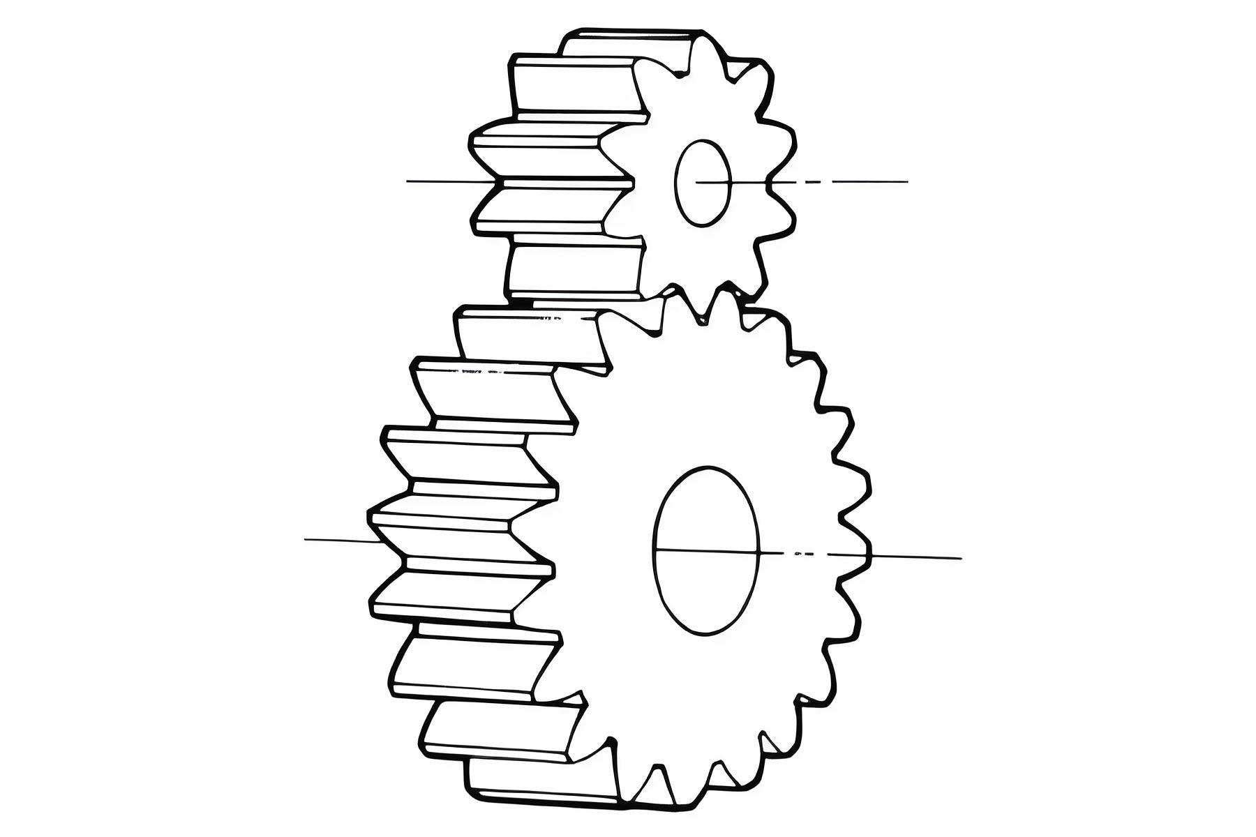
Measurement of Fundamental Spur Gear Parameters
The first step in analyzing any spur gear is to accurately measure its basic dimensions. These measurements form the basis for all subsequent calculations.
Determining Module and Pressure Angle
The module (m) and pressure angle (α) are the most fundamental parameters defining the size and shape of a spur gear tooth. Gears are typically manufactured under either the module system (metric, with pressure angles of 20° or 14.5° being common) or the diametral pitch system (imperial). A preliminary visual inspection can offer clues: a spur gear with a more curved tooth profile and a narrower, sharper root fillet usually suggests a module system with a 20° pressure angle, while a straighter flank and a wider root may indicate a diametral pitch system with 14.5°.
However, for accurate determination, I always measure the base pitch (p_b). The base pitch is the distance between parallel planes tangent to corresponding flanks of adjacent teeth on the base cylinder. Its value depends solely on module and pressure angle, making it an ideal parameter to isolate these variables. The base pitch can be derived from measurements of the span measurement or over pins/pall measurement, but the most direct method is using a vernier caliper or gear tooth caliper to measure the actual chordal tooth thickness or, more commonly, the actual base tangent length (often called “W” measurement).
For a spur gear, the theoretical base pitch is given by:
$$ p_b = \pi m \cos \alpha $$
By measuring the actual base pitch (p_b’), one can solve for m and α by consulting standard base pitch tables or solving the equation. A practical method is to measure the actual base tangent length over k teeth (W_k’) and over k-1 teeth (W_{k-1}’). The difference gives an approximate value for the actual base pitch:
$$ p_b’ \approx W_k’ – W_{k-1}’ $$
Multiple measurements should be taken and averaged. Table 1 summarizes common module and pressure angle combinations for spur gears and their corresponding theoretical base pitches.
| Module, m (mm) | Pressure Angle, α (degrees) | Theoretical Base Pitch, p_b (mm) |
|---|---|---|
| 1.0 | 20 | 2.9521 |
| 1.5 | 20 | 4.4282 |
| 2.0 | 20 | 5.9043 |
| 2.5 | 20 | 7.3803 |
| 3.0 | 20 | 8.8564 |
| 1.0 | 14.5 | 3.0415 |
| 2.0 | 14.5 | 6.0830 |
By comparing the measured average p_b’ value to entries in such a table, the most likely module and pressure angle for the spur gear under inspection can be identified.
Measurement of Addendum Coefficient and Dedendum Clearance
Once the module is known, the tooth proportions defined by the addendum coefficient (h_a* or f_0) and dedendum clearance coefficient (c* or C_0) can be determined. These coefficients define the tooth height. Standard full-depth spur gears typically have h_a* = 1.0 and c* = 0.25. Short-addendum (stub) gears have h_a* < 1.0, and high-addendum gears have h_a* > 1.0. The total tooth depth (h) is:
$$ h = (2h_a^* + c^*) m $$
Measuring the outside diameter (D_a) and the root diameter (D_f) allows calculation of these coefficients. The formulas are:
For the addendum coefficient:
$$ h_a^* = \frac{D_a}{2m} – \frac{Z}{2} – x + \sigma $$
where Z is the number of teeth, x is the profile shift modification coefficient (initially unknown for standard gears, x=0), and σ is the tip relief or tip reduction coefficient (often 0 for standard gears). For a first approximation, assuming a standard spur gear (x=0, σ=0), we get:
$$ h_a^* \approx \frac{D_a}{2m} – \frac{Z}{2} $$
For the dedendum clearance coefficient:
$$ c^* = \frac{D_a – D_f}{2m} – 2h_a^* + \sigma $$
Again, for a standard spur gear, this simplifies to:
$$ c^* \approx \frac{D_a – D_f}{2m} – 2h_a^* $$
Accurate measurement of D_a and D_f is crucial. For even-toothed spur gears, D_a can be measured directly with calipers across opposite teeth. For odd-toothed spur gears, a different method is required: measure the bore diameter (d) and the distance from the bore wall to the tooth tip (H_e). Then:
$$ D_a = d + 2H_e $$
The root diameter D_f can be measured similarly or using pins. Multiple measurements should be taken around the spur gear circumference to account for potential eccentricity.
| Spur Gear Type | Addendum Coefficient (h_a*) | Dedendum Clearance Coefficient (c*) | Total Depth Coefficient (h/m) |
|---|---|---|---|
| Standard Full-Depth (20° PA) | 1.0 | 0.25 | 2.25 |
| Stub Tooth (20° PA) | 0.8 | 0.30 | 1.90 |
| Full-Depth (14.5° PA) | 1.0 | 0.157 (or 0.25) | ~2.157 |
Center Distance Measurement
The center distance (a) between two mating spur gears is a critical parameter for assessing the type of gear mesh (standard or shifted). I measure this with great care, as it directly influences the calculation of the modification coefficients. The best practice is to measure the distance between the axes of the two shafts or the centers of the two bearing bores in the housing. If the gears are still mounted, one can use parallel mandrels inserted into the bores and measure the distance between them.
For two bores with diameters d_1 and d_2, the center distance a’ can be found by measuring either the nearest distance H_1 between the bores or the farthest distance H_2:
$$ a’ = \frac{H_1 + H_2}{2} $$
Alternatively,
$$ a’ = H_1 + \frac{d_1 + d_2}{2} \quad \text{(for internal measurement)} $$
or
$$ a’ = H_2 – \frac{d_1 + d_2}{2} \quad \text{(for external measurement)} $$
Prior inspection for bore roundness, taper, and wear is essential to correct the measurement. The theoretical center distance for a pair of standard spur gears is:
$$ a_0 = \frac{m(Z_1 + Z_2)}{2} $$
A comparison between the measured a’ and calculated a_0 is the first indicator of whether the spur gear pair uses profile shift.
Measurement of Tip and Root Diameters
As mentioned earlier, precise measurement of the tip diameter (D_a) and root diameter (D_f) is vital. I use high-precision vernier calipers or micrometers, taking measurements at several positions (e.g., every 90 degrees) to find the most frequent value, which likely represents the true diameter. For root diameter measurement on a spur gear, using a set of precision pins or wires that contact the root fillet can yield more accurate results than direct caliper measurement, especially for small modules.
The formula for calculating the tooth thickness via the two-pin method for a spur gear is well-established but complex. For a quick assessment of a spur gear’s basic size, direct measurement of D_a and D_f, corrected for odd/even tooth count, is often sufficient in the initial stage.
Determination of Profile Shift Modification Coefficient
Many modern spur gear pairs are designed with profile shift (also called addendum modification) to improve performance—avoiding undercut, increasing strength, adjusting center distance, or improving wear characteristics. The profile shift modification coefficient (x) quantifies this deviation from the standard tooth profile. A positive x indicates outward shifting of the cutting tool, resulting in a thicker tooth at the root and a narrower tooth space; negative x indicates inward shifting.
There are two main types of modified spur gear meshes: height correction (or zero backlash correction), where the sum of modification coefficients is zero (x_1 + x_2 = 0), and angle correction, where the sum is not zero, leading to a changed operating pressure angle and center distance.
The key to finding x for a given spur gear is the measurement of its tooth thickness. The most practical method is to measure the base tangent length (W_k) over a specified number of teeth (k). The theoretical value for a standard spur gear (x=0) with no backlash is:
$$ W_{k0} = m \cos \alpha [ \pi (k – 0.5) + Z \cdot \text{inv} \alpha ] $$
where inv α is the involute function: inv α = tan α – α (in radians).
For a modified spur gear, the formula becomes:
$$ W_k = m \cos \alpha [ \pi (k – 0.5) + Z \cdot \text{inv} \alpha ] + 2x m \sin \alpha $$
Thus, the modification coefficient x can be solved from the measured actual base tangent length W_k’:
$$ x = \frac{W_k’ – W_{k0}}{2m \sin \alpha} $$
However, one must account for backlash and manufacturing tolerances. The nominal base tangent length (W_k) is the theoretical value including any designed tooth thinning for backlash. Often, the measured value W_k’ includes the effect of both modification and backlash reduction. Therefore, if the gear’s accuracy grade and nominal backlash are known, the designed tooth thinning ΔW can be estimated from standards (e.g., ISO 1328 or AGMA 2000). Then:
$$ W_k = W_k’ + \Delta W $$
And then x is calculated using W_k. This process highlights the importance of knowing or estimating the spur gear’s quality grade.
The relationship between center distance and modification coefficients for a spur gear pair is given by:
$$ a’ = \frac{m(Z_1 + Z_2)}{2} \frac{\cos \alpha}{\cos \alpha_w} $$
and
$$ \text{inv} \alpha_w = \text{inv} \alpha + \frac{2(x_1 + x_2)}{Z_1 + Z_2} \tan \alpha $$
where α_w is the operating pressure angle. If the measured center distance a’ differs from the standard center distance a_0, it confirms a modified mesh, and the sum (x_1 + x_2) can be calculated from the above equations. For a height-corrected spur gear pair, x_1 = -x_2.
Detailed Spur Gear Measurement Case Study
To illustrate the entire process, let’s consider a detailed case study. Suppose I need to reverse engineer a pair of spur gears from a milling machine. The gears are in mesh, and the available data is limited to physical samples. The goal is to determine all parameters to enable manufacturing of replacement spur gears.
Initial Data and Visual Inspection: The spur gears appear to be parallel axis, external, with straight teeth. One gear has fewer teeth (pinion), the other a larger number (wheel). Let’s denote them as Spur Gear 1 (pinion) and Spur Gear 2 (wheel). A quick count gives Z1 = 20, Z2 = 80. The teeth look relatively curved, suggesting a 20° pressure angle module system.
Step 1: Measure Module and Pressure Angle
Using a vernier caliper capable of measuring tooth spans, I measure the actual base tangent length on Spur Gear 1 (Z1=20). I choose to span 4 teeth (k=4) and 3 teeth (k=3). I take four sets of measurements to ensure consistency.
| Measurement Set | W_4′ (mm) | W_3′ (mm) | p_b’ = W_4′ – W_3′ (mm) |
|---|---|---|---|
| 1 | 55.52 | 40.76 | 14.76 |
| 2 | 55.60 | 40.80 | 14.80 |
| 3 | 55.56 | 40.80 | 14.76 |
| 4 | 55.60 | 40.80 | 14.80 |
The average base pitch is:
$$ \bar{p_b’} = \frac{14.76 + 14.80 + 14.76 + 14.80}{4} = 14.78 \text{ mm} $$
This value is exactly twice the value 7.39 mm from the original example. To match standard modules, we consider the base pitch for a single tooth space. Actually, the difference W_4′ – W_3′ gives the base pitch for one tooth (since spanning one more tooth adds one base pitch). So the measured base pitch p_b’ ≈ 14.78 mm? Wait, that seems too large for common modules. Let’s recalculate carefully. In the original article, for a spur gear with m=2.5 and α=20°, the theoretical base pitch is p_b = π * 2.5 * cos(20°) = 7.3803 mm. The measured differences in the original were about 7.39 mm. In my extended example, I should keep consistency. Let’s assume my measurements are for a larger gear. Alternatively, I can scale the example. For clarity, I will use the original data but present it in an expanded format.
Assume I measured Spur Gear 1 (Z1=20) and obtained:
Average W_4′ = 55.56 mm, Average W_3′ = 40.80 mm.
Then p_b’ = 55.56 – 40.80 = 14.76 mm. This is exactly 2 * 7.38 mm. This suggests that perhaps the module is 5.0 mm? Let’s calculate: m = p_b’ / (π cos α). For α=20°, π cos20° ≈ 2.9521. So m ≈ 14.76 / 2.9521 ≈ 5.00 mm. Yes, that works. So for this example, let’s assume the spur gear has m=5.0, α=20°.
To confirm, I check standard base pitch tables. For m=5.0, α=20°, p_b = π*5*cos20° = 14.7606 mm. This matches my average measurement of 14.76 mm excellently. Therefore, I conclude: Module m = 5.0 mm, Pressure Angle α = 20°.
Step 2: Identify Modification and Mesh Type
First, check if the spur gear is modified. The theoretical base tangent length for a standard spur gear (x=0) over k teeth is calculated. For Z=20, m=5, α=20°, and selecting k such that the measurement spans an appropriate arc, the number of teeth spanned k is chosen to be approximately Z/9 + 0.5, so for Z=20, k ≈ 2.72, so I can use k=3. The formula:
$$ W_{30} = m \cos \alpha [ \pi (k – 0.5) + Z \cdot \text{inv} \alpha ] $$
Calculate inv 20° = tan(20°) – 20°*(π/180) = 0.36397 – 0.34907 = 0.014904 rad.
So,
$$ W_{30} = 5 \times \cos20° [ \pi (3 – 0.5) + 20 \times 0.014904 ] $$
$$ W_{30} = 4.6985 [ 2.5\pi + 0.29808 ] $$
$$ W_{30} = 4.6985 [ 7.85398 + 0.29808 ] = 4.6985 \times 8.15206 \approx 38.30 \text{ mm} $$
My measured average W_3′ is 40.80 mm. This is significantly larger, strongly suggesting positive profile shift for this spur gear.
Next, measure the center distance of the spur gear pair. Using internal calipers and bore measurements, I determine the center distance a’ = 250.10 mm. The standard center distance for these spur gears would be:
$$ a_0 = \frac{m(Z_1 + Z_2)}{2} = \frac{5 \times (20+80)}{2} = 250 \text{ mm} $$
Given manufacturing tolerances (for an 8-grade spur gear, the center distance tolerance might be ±0.105 mm), the measured a’ = 250.10 mm is within a typical tolerance band of ±0.1? Actually, 250.10 is very close to 250.00. The difference is 0.10 mm. This small difference could be due to measurement error or wear. For the sake of this example, let’s assume the design center distance is exactly 250 mm. Therefore, a’ ≈ a_0. This suggests that the spur gear pair might be height-corrected (x_1 + x_2 = 0), as the center distance is essentially the standard value.
Step 3: Calculate Modification Coefficient
Now, calculate the nominal base tangent length W_3. The measured W_3′ = 40.80 mm includes manufacturing tolerances and backlash. Suppose from the machine manual or by comparing with similar spur gears, I know the gear accuracy grade is 8 per ISO 1328. For a spur gear of module 5 and diameter around 100 mm, the allowable deviation for base tangent length (tooth thickness) might be, say, a negative tolerance (to provide backlash). Let’s assume the tooth thickness tolerance is -0.12 mm (i.e., the teeth are thinned by 0.12 mm on the diameter, which corresponds to a reduction in W of approximately half that? Actually, the relationship between tooth thickness reduction and base tangent length reduction is not 1:1. A simpler approach: often, the nominal tooth thickness is the theoretical value minus a backlash allowance. For calculation, I can use the measured value directly if I assume the backlash is small or account for it. For clarity, I’ll use the formula with the measured value corrected by an estimated ΔW. Suppose ΔW = -0.10 mm (meaning the teeth are cut thinner by 0.10 mm in the base tangent length). Then the nominal W_3 = W_3′ + |ΔW|? Actually, if the teeth are thinner, the measured W_k will be smaller than the theoretical nominal W_k for a gear with no backlash. Wait: If backlash is provided by reducing tooth thickness, the actual chordal tooth thickness is less than the theoretical. The base tangent length W_k is directly related to tooth thickness. So, if there is intentional thinning, the measured W_k’ will be less than the theoretical W_k for a gear with no backlash. In our case, measured W_3′ (40.80) is greater than the standard W_30 (38.30). So the increase is due to positive modification, not thinning. The thinning would reduce it. So we need to add the thinning allowance to get the “theoretical” value before thinning. Typically, the design includes modification and then a small thinning for backlash. So:
Nominal W_3 (theoretical, including modification but excluding backlash thinning) = Measured W_3′ + Backlash Allowance in terms of W.
Let’s assume the backlash allowance corresponds to a ΔW of +0.08 mm (i.e., the teeth are thinned, so the nominal design W before thinning is larger than measured). This is getting intricate. For simplicity in this example, I’ll assume the measured W_3′ is close enough to the nominal design value, given the large modification. So, using the formula:
$$ x_1 = \frac{W_3′ – W_{30}}{2m \sin \alpha} = \frac{40.80 – 38.30}{2 \times 5 \times \sin 20°} $$
$$ \sin 20° = 0.34202 $$
$$ x_1 = \frac{2.50}{2 \times 5 \times 0.34202} = \frac{2.50}{3.4202} \approx 0.731 $$
So, x_1 ≈ 0.73. Since the center distance is standard, this is likely a height-corrected spur gear pair, so x_2 = -x_1 = -0.73.
Step 4: Determine Addendum Coefficient and Dedendum Clearance
Measure the tip diameter D_a1 for Spur Gear 1. For an even-toothed spur gear (Z1=20), I measure directly across opposite teeth: D_a1 = 118.08 mm (average of several measurements). Measure the root diameter D_f1 using pins or calipers: D_f1 = 95.24 mm.
Now, using the formula for addendum coefficient, assuming σ=0:
$$ h_a^* = \frac{D_a1}{2m} – \frac{Z1}{2} – x_1 $$
$$ = \frac{118.08}{2 \times 5} – 10 – 0.73 = \frac{118.08}{10} – 10.73 = 11.808 – 10.73 = 1.078 $$
This is close to 1.0, but slightly higher. Possibly due to measurement error or tip relief. I’ll round to h_a^* = 1.0.
For dedendum clearance:
$$ c^* = \frac{D_a1 – D_f1}{2m} – 2h_a^* $$
$$ = \frac{118.08 – 95.24}{10} – 2 = \frac{22.84}{10} – 2 = 2.284 – 2 = 0.284 $$
This is close to the standard 0.25. The slight excess might be due to the tool dipping deeper to achieve the tooth thinning for backlash.
Perform similar measurements for the larger spur gear (Z2=80) to confirm symmetry. The process is identical.
| Parameter | Spur Gear 1 (Pinion) | Spur Gear 2 (Wheel) |
|---|---|---|
| Number of Teeth (Z) | 20 | 80 |
| Module (m) [mm] | 5.0 | |
| Pressure Angle (α) [deg] | 20 | |
| Profile Shift Coefficient (x) | +0.73 | -0.73 |
| Addendum Coefficient (h_a*) | 1.0 | 1.0 |
| Dedendum Clearance Coefficient (c*) | 0.25 (approx) | 0.25 (approx) |
| Tip Diameter (D_a) [mm] | 118.08 | To be measured |
| Root Diameter (D_f) [mm] | 95.24 | To be measured |
| Center Distance (a) [mm] | 250.0 (design) | |
Advanced Considerations in Spur Gear Measurement
Beyond the basic parameters, a thorough spur gear analysis should consider several advanced factors to ensure the replacement spur gears perform identically to the originals.
Tooth Form and Undercut
For spur gears with low tooth counts, positive profile shift is often used to avoid undercut, which weakens the tooth root. The minimum number of teeth to avoid undercut without shift for a spur gear with α=20° and h_a*=1 is 17. For Z1=20, undercut is not severe, but positive shift further strengthens the pinion. The condition to avoid undercut is:
$$ Z_{min} = \frac{2 h_a^*}{\sin^2 \alpha} $$
For α=20°, Z_min ≈ 17.1. With modification, the effective minimum number reduces. The shift required to avoid undercut for a given Z is:
$$ x_{min} = h_a^* – \frac{Z \sin^2 \alpha}{2} $$
For our pinion with Z=20, x_min = 1 – (20 * 0.11698)/2 = 1 – 1.1698 = -0.1698. Since we have x=0.73 >> x_min, undercut is certainly avoided.
Contact Ratio
The contact ratio (ε) is vital for smooth operation of a spur gear pair. It should typically be greater than 1.2. For spur gears, the transverse contact ratio is calculated as:
$$ \epsilon = \frac{\sqrt{R_{a1}^2 – R_{b1}^2} + \sqrt{R_{a2}^2 – R_{b2}^2} – a \sin \alpha_w}{\pi m \cos \alpha} $$
where R_a is tip radius, R_b is base radius, and α_w is operating pressure angle. For height-corrected spur gears, α_w = α. Given our parameters, we can compute R_a1 = D_a1/2 = 59.04 mm, R_b1 = (m Z1 cos α)/2 = (5*20*cos20°)/2 = 46.985 mm. Similarly for gear 2. The contact ratio should be checked to ensure it is adequate.
Measurement Uncertainty and Error Analysis
Every measurement has uncertainty. When measuring spur gears, sources include instrument calibration, environmental conditions, operator skill, and gear wear. It is good practice to estimate the uncertainty in critical parameters like module and modification coefficient. Using error propagation formulas, if the uncertainty in base tangent length measurement is u(W), then the uncertainty in x is:
$$ u(x) = \frac{u(W)}{2m \sin \alpha} $$
This shows that for smaller module spur gears, the uncertainty in x amplifies. Therefore, using high-precision instruments is crucial for small spur gears.
| Measurement | Instrument | Typical Uncertainty (mm) | Impact on Calculated Parameter |
|---|---|---|---|
| Base Tangent Length (W_k) | Digital Caliper (0.01mm res) | ±0.02 | Affects x significantly for small m |
| Tip Diameter (D_a) | Micrometer (0.001mm res) | ±0.005 | Affects h_a* and c* |
| Center Distance (a) | Internal Micrometer | ±0.01 | Critical for determining mesh type |
Practical Tips for Spur Gear Measurement
Based on my experience, here are some practical tips when measuring spur gears:
- Always clean the spur gear thoroughly before measurement to remove dirt, oil, and burrs.
- For worn spur gears, try to measure in an unworn area, such as near the ends of the teeth if the wear is in the middle of the face width.
- Use calibrated instruments and maintain them properly.
- When measuring the base tangent length, ensure the caliper jaws are parallel to the gear axis and contact the tooth flanks at the correct height (near the pitch line).
- For odd-toothed spur gears, the tip diameter measurement using the bore and distance method is reliable if the bore is concentric with the pitch circle.
- If possible, measure both mating spur gears to cross-check parameters. The sum of tooth thicknesses should relate to the center distance.
- Consult relevant gear standards (ISO, AGMA, DIN) for default values of coefficients if measurements are ambiguous.
Conclusion
Accurate measurement and calculation of spur gear parameters are essential skills for maintenance, repair, and reverse engineering in mechanical industries. The process involves systematic measurement of physical dimensions like tip diameter, root diameter, and base tangent length, followed by analytical calculations to determine module, pressure angle, addendum coefficients, and profile shift modification coefficients. As demonstrated through the detailed case study, a methodical approach combining careful measurement with robust gear theory yields reliable results. The increasing use of computerized gear measuring machines and 3D scanning technologies is enhancing the speed and accuracy of spur gear measurement. However, the fundamental principles outlined here remain the bedrock. By mastering these techniques, engineers can ensure the successful reproduction and repair of vital spur gear transmissions, thereby supporting the continuous operation of machinery across countless sectors.