
In the realm of heavy-duty power transmission, particularly for low-speed and high-torque applications, the herringbone gear stands out due to its exceptional performance characteristics. Unlike traditional spur or helical gears, the herringbone gear features a unique double-helical design that cancels out axial thrust forces, leading to smoother operation, reduced vibration, and lower noise levels. This makes herringbone gears indispensable in industries such as marine propulsion, industrial machinery, and wind turbines. However, the manufacturing of herringbone gears, especially through hobbing processes, presents significant challenges, primarily centered around the alignment error of the spiral lines. This error, if not properly controlled, can severely impact gear meshing quality, load capacity, and overall assembly feasibility. In this comprehensive analysis, I will delve into the intricacies of spiral line alignment error in herringbone gear hobbing, exploring its relationship with backlash and helix angle, proposing measurement techniques, and discussing practical installation methods to mitigate its effects.
The core issue in herringbone gear manufacturing lies in ensuring that the left-hand and right-hand helical tooth traces intersect precisely at the midpoint of the groove. Any deviation from this ideal intersection point constitutes the alignment error. For herringbone gears, this error is critical because it directly affects the simultaneous engagement of both helical halves. If the alignment is off, only one side of the herringbone gear may carry the load initially, leading to uneven stress distribution, increased wear, and potential failure. Moreover, excessive alignment error can cause assembly difficulties, as the gears may not mesh properly or at all. While standards exist for alignment tolerances in involute herringbone gears, such as allowing up to 0.5 mm for Grade 8 gears and 0.2 mm for Grade 7 and above, these tolerances are often insufficient for double-circular-arc herringbone gears, especially those with small to medium modules. The unique tooth profile of double-circular-arc herringbone gears demands stricter control over alignment errors to maintain their superior load-carrying capacity and meshing performance.
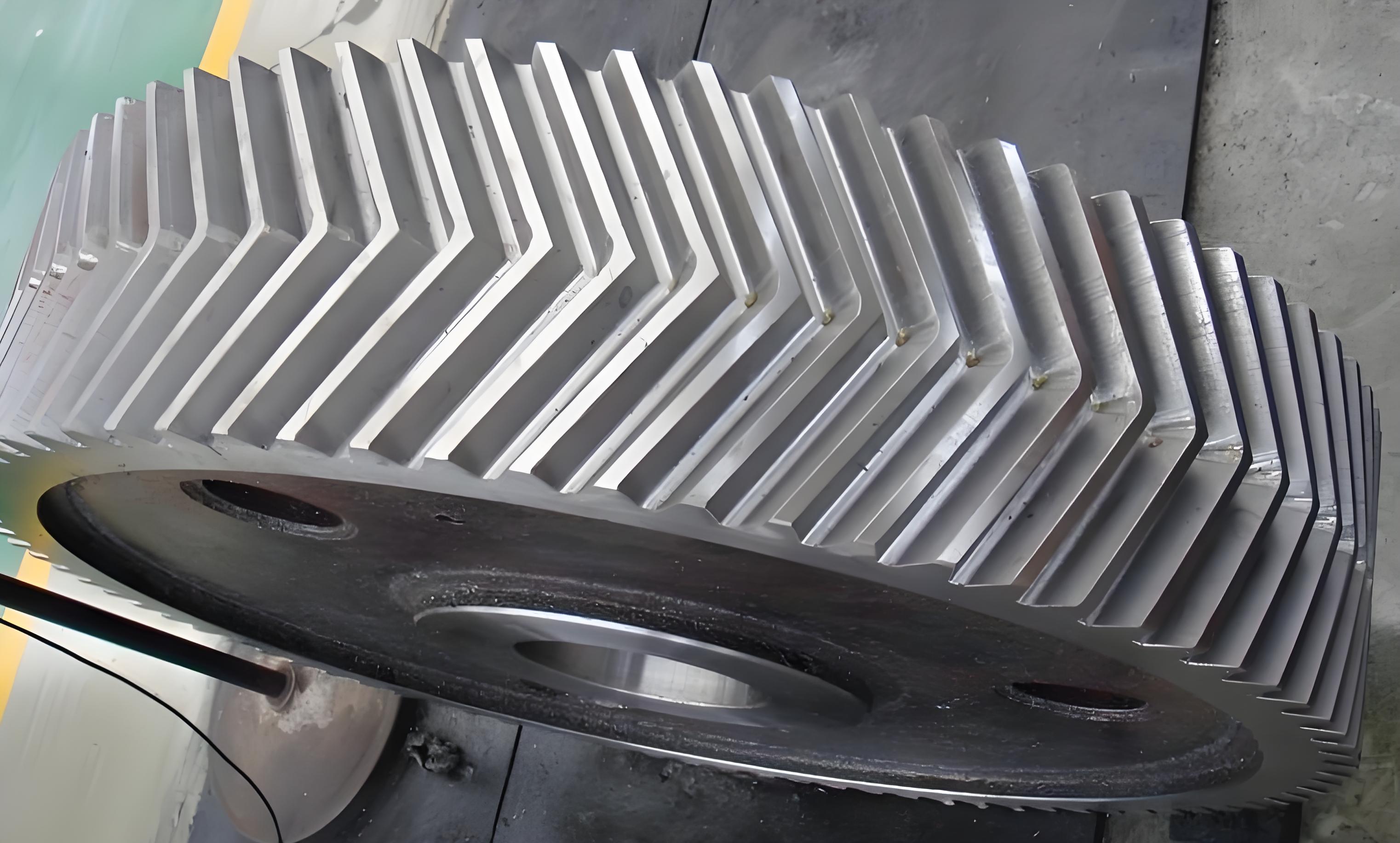
To understand the alignment error, we must first define its components. In the context of herringbone gear hobbing, the alignment error can be measured in two directions: vertical (along the axis of the gear) and horizontal (perpendicular to the axis). Let’s denote the vertical alignment error as δH, which represents the difference in height between the left-hand and right-hand tooth trace extensions at the groove centerline. The maximum allowable vertical error is denoted as TH. Similarly, the horizontal alignment error, denoted as TV, represents the displacement of the intersection point of the two tooth traces from the groove centerline. These parameters are intrinsically linked to the gear’s design parameters, specifically the normal backlash jn and the helix angle β. Through geometric analysis of the herringbone gear meshing, we can derive the following fundamental relationships:
$$ T_H = \frac{j_n}{\cos \beta} $$
$$ T_V = \frac{j_n}{2 \sin \beta} $$
These equations reveal that the maximum allowable alignment error is not a fixed value but varies with both backlash and helix angle. For a given herringbone gear, the normal backlash jn is typically determined by the module mn according to industry standards. For instance, based on the JB2940-81 standard, the normal backlash for double-circular-arc gears can be calculated as follows: when mn ≤ 6 mm, jn = 0.06 mn; when mn > 6 mm, jn = 0.04 mn. This relationship underscores the importance of module selection in herringbone gear design and its impact on alignment tolerances. To illustrate, let’s consider a range of modules and compute the corresponding normal backlash values:
| Module mn (mm) | 4 | 4.5 | 5 | 5.5 | 6 | 7 | 8 | 9 | 10 |
|---|---|---|---|---|---|---|---|---|---|
| Normal Backlash jn (mm) for mn ≤ 6 | 0.24 | 0.27 | 0.30 | 0.33 | 0.36 | – | – | – | – |
| Normal Backlash jn (mm) for mn > 6 | – | – | – | – | – | 0.28 | 0.32 | 0.36 | 0.40 |
With these backlash values, we can now examine how the helix angle β influences the maximum allowable alignment errors TH and TV. The helix angle is a critical design parameter for herringbone gears, typically ranging from 15° to 45°, depending on the application requirements. A larger helix angle increases the contact ratio and smoothness of operation but also amplifies the alignment sensitivity. Using the formulas above, we can generate a comprehensive table showing TH and TV for various combinations of jn and β:
| Helix Angle β (°) | Normal Backlash jn (mm) | Vertical Allowable Error TH (mm) | Horizontal Allowable Error TV (mm) |
|---|---|---|---|
| 15 | 0.24 | 0.248 | 0.464 |
| 0.27 | 0.279 | 0.522 | |
| 0.30 | 0.310 | 0.580 | |
| 0.33 | 0.341 | 0.638 | |
| 0.36 | 0.372 | 0.696 | |
| 0.40 | 0.413 | 0.773 | |
| 25 | 0.24 | 0.265 | 0.284 |
| 0.27 | 0.298 | 0.319 | |
| 0.30 | 0.331 | 0.355 | |
| 0.33 | 0.364 | 0.390 | |
| 0.36 | 0.397 | 0.426 | |
| 0.40 | 0.441 | 0.473 | |
| 30 | 0.24 | 0.277 | 0.240 |
| 0.27 | 0.312 | 0.270 | |
| 0.30 | 0.346 | 0.300 | |
| 0.33 | 0.381 | 0.330 | |
| 0.36 | 0.416 | 0.360 | |
| 0.40 | 0.462 | 0.400 |
This table clearly demonstrates that as the helix angle increases, TH generally increases while TV decreases. For instance, at jn = 0.30 mm, TH rises from 0.310 mm at β=15° to 0.346 mm at β=30°, whereas TV drops from 0.580 mm to 0.300 mm. This inverse relationship highlights the need for careful consideration of both error directions during herringbone gear manufacturing. In practice, the vertical alignment error δH is often easier to measure and control, making TH the primary criterion for alignment tolerance. However, it is crucial to note that the above values represent the maximum allowable errors assuming one gear in the pair is perfectly manufactured. In reality, both herringbone gears in a mating pair will have their own alignment errors. Therefore, to ensure interchangeable assembly and proper meshing, the actual machining error for a single herringbone gear should be controlled within half of these maximum values:
$$ \delta_H \leq \frac{T_H}{2} $$
$$ \delta_V \leq \frac{T_V}{2} $$
This halving of tolerances underscores the precision required in herringbone gear hobbing. For example, if a herringbone gear has a helix angle of 25° and a normal backlash of 0.30 mm, then TH ≈ 0.331 mm, so the vertical alignment error during machining should be kept below 0.1655 mm. Achieving such tight tolerances demands advanced manufacturing techniques and rigorous process control.
The measurement of alignment error in herringbone gears is a critical step in quality assurance. Typically, the vertical alignment error δH is measured by positioning the herringbone gear on a precision mandrel and using a height gauge or coordinate measuring machine (CMM) to determine the height difference between the left-hand and right-hand tooth traces at the groove center. The gear is referenced from its outer diameter for stability. The process involves selecting a reference tooth and measuring the heights hleft and hright of the corresponding tooth tips on either side of the groove. The alignment error is then calculated as δH = hright – hleft. For enhanced accuracy, multiple teeth around the circumference should be measured to account for any indexing errors. Alternatively, optical projection or laser scanning methods can be employed for non-contact measurement, providing high-resolution data on tooth trace geometry. It is essential to perform these measurements in a controlled environment to minimize thermal and vibrational influences. The horizontal alignment error δV is more challenging to measure directly but can be inferred from the vertical measurements using the geometric relationships or through specialized fixtures that simulate meshing conditions.
Beyond measurement, the control of backlash in herringbone gears differs significantly from that in involute gears. For involute herringbone gears, backlash is typically managed by adjusting tooth thickness or controlling chordal dimensions during hobbing. This adjustment does not inherently affect tooth profile accuracy. In contrast, for double-circular-arc herringbone gears, the backlash is inherently determined by the hob tooth profile. Since double-circular-arc gears have a non-separable center distance, the depth of cut during hobbing must be precisely controlled. Cutting too shallow or too deep will alter the tooth profile, shifting the contact pattern and degrading meshing performance. Therefore, maintaining consistent cutting depth is paramount for achieving the designated backlash and ensuring optimal contact conditions. This adds another layer of complexity to herringbone gear manufacturing, as any variation in hob wear or machine setup can lead to deviations in both backlash and alignment.
Given the challenges in achieving perfect alignment during machining, a practical approach to mitigating alignment errors in herringbone gear pairs is through selective assembly or matching. This method involves measuring the alignment errors of individual herringbone gears and then pairing them in such a way that the errors compensate for each other. The fundamental principle for selective assembly can be expressed as:
$$ |\delta_{H1} – \delta_{H2}| \leq T_H $$
where δH1 is the vertical alignment error of the first herringbone gear (e.g., the large gear) and δH2 is that of the second herringbone gear (e.g., the pinion or gear shaft). If the alignment error of one herringbone gear is such that the right-hand teeth are higher than the left-hand teeth, then it should be paired with another herringbone gear where the left-hand teeth are higher than the right-hand teeth. This counterbalancing effect can effectively cancel out the net alignment error in the meshing pair, allowing for proper engagement and load sharing. Selective assembly is particularly valuable in small-batch production or repair scenarios where machining precision may be limited. For instance, if herringbone gears are manufactured using traditional methods like marking and manual alignment on the hobbing machine, alignment errors can be variable and unpredictable. By categorizing gears based on their measured alignment errors and pairing them strategically, manufacturers can achieve functional herringbone gear assemblies even when individual components exceed half-tolerance limits. This approach not only facilitates assembly but also enhances the operational smoothness and longevity of the herringbone gear transmission.
To delve deeper into the theoretical aspects, let’s consider the impact of alignment error on the load distribution and stress concentration in herringbone gears. When alignment error is present, the initial contact occurs on only one helical flank, leading to a skewed load distribution across the tooth width. This can be modeled using load-sharing factors and finite element analysis. The effective contact ratio, which is crucial for smooth power transmission, may be reduced, resulting in increased transmission error and noise. Moreover, the misalignment induces bending moments on the teeth, potentially leading to premature fatigue failure. The relationship between alignment error and dynamic performance can be expressed through modifications to the gear mesh stiffness function. For a herringbone gear with alignment error, the time-varying mesh stiffness K(t) can be approximated as:
$$ K(t) = K_0 \left[1 – \epsilon \cdot \sin(\omega t + \phi)\right] $$
where K0 is the nominal mesh stiffness, ε is an error coefficient proportional to δH, ω is the mesh frequency, and φ is a phase angle. This modulation in stiffness can excite resonant frequencies, leading to vibration amplification. Therefore, minimizing alignment error is not just about assembly fit but also about ensuring the dynamic integrity of the herringbone gear system.
In addition to hobbing, other manufacturing processes for herringbone gears, such as shaping, grinding, or additive manufacturing, also face alignment challenges. Each process has its own error sources. For example, in grinding, wheel wear and dressing errors can introduce spiral line deviations. Advanced CNC machines with real-time compensation algorithms can help mitigate these errors by adjusting tool paths based on in-process measurements. Furthermore, the design of the herringbone gear itself can be optimized to be more tolerant to alignment errors. For instance, increasing the groove width or using modified tooth profiles with tip relief can accommodate slight misalignments without compromising performance. However, these modifications must be balanced against other design constraints like strength and efficiency.
The role of lubrication in herringbone gears with alignment errors cannot be overlooked. Misalignment can alter the elastohydrodynamic lubrication (EHL) film thickness between meshing teeth, potentially leading to boundary lubrication conditions and increased wear. Proper lubricant selection and supply are essential to maintain a protective film, especially in high-load applications. The alignment error may also affect the distribution of lubricant across the tooth faces, necessitating tailored oil jet placements or splash patterns.
From a quality control perspective, statistical process control (SPC) can be applied to monitor alignment errors in herringbone gear production. By collecting data on δH and δV from a sample of gears, manufacturers can establish control charts to detect trends or shifts in the manufacturing process. Capability indices like Cpk can be calculated to assess whether the process can consistently meet the tolerance requirements. This data-driven approach enables proactive adjustments, reducing scrap and rework.
In summary, the spiral line alignment error in herringbone gear hobbing is a multifaceted issue that intertwines design, manufacturing, and assembly. The maximum allowable alignment error is governed by the relationships TH = jn / cos β and TV = jn / (2 sin β), where jn is the normal backlash and β is the helix angle. For practical manufacturing, the actual error per herringbone gear should be kept within half of these values to ensure pair-wise compatibility. Vertical alignment error is typically the preferred measurement due to its simplicity. However, the unique nature of double-circular-arc herringbone gears requires stringent control over cutting depth to maintain both backlash and tooth profile accuracy. When machining precision is challenging, selective assembly offers an effective remedy by pairing herringbone gears with compensating errors. This strategy not only solves assembly issues but also enhances the meshing quality and durability of the herringbone gear transmission. As technology advances, integrating real-time monitoring and adaptive control in hobbing machines will further reduce alignment errors, pushing the performance boundaries of herringbone gears in demanding applications. The continuous pursuit of precision in herringbone gear manufacturing is essential for harnessing their full potential in power transmission systems.