
In modern mechanical transmission systems, especially in aerospace applications, herringbone gears are widely used due to their high load-carrying capacity, smooth operation, and compact design. However, vibration and noise generated during meshing can significantly impact performance and reliability. Understanding the dynamic behavior of herringbone gear systems is crucial for optimizing design and reducing unwanted oscillations. This article explores the influence of meshing stiffness and damping on the vibration characteristics of herringbone gears through a comprehensive dynamic model and numerical analysis. I will present a detailed study based on a bending-torsional-axial coupling model, emphasizing the role of stiffness fluctuations and damping in mitigating vibrations.
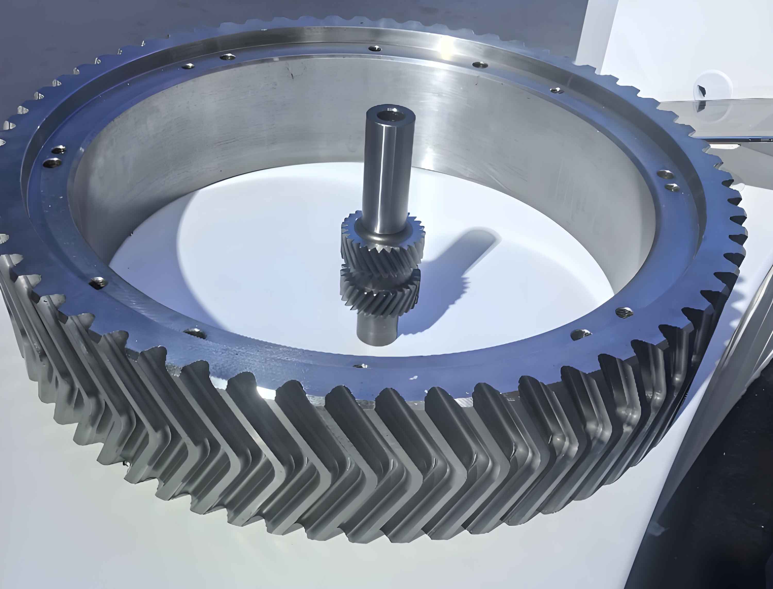
Herringbone gears consist of two helical gears with opposite hand orientations, effectively canceling axial thrust forces. Despite their advantages, the complex interaction between left and right helical segments introduces unique dynamic challenges. Vibration in herringbone gears primarily stems from internal excitations such as time-varying meshing stiffness, manufacturing errors, and impact forces. These excitations can lead to increased dynamic loads, noise, and even fatigue failure. Therefore, analyzing the dynamic response under varying parameters like stiffness and damping is essential for improving gear system design. In this context, I develop a coupled dynamic model to simulate the system behavior and assess how changes in meshing stiffness and damping affect vibration amplitudes.
The dynamic model for herringbone gears considers multiple degrees of freedom, including transverse, axial, and torsional vibrations. I assume the herringbone gear pair as two symmetric helical gear pairs with identical parameters but opposite helix directions. The system includes masses, moments of inertia, stiffness, and damping elements for both the pinion and gear on left and right sides. Coupling between the sides arises from axial and bending interactions. The governing equations of motion are derived using Newton’s second law, incorporating excitations from meshing stiffness variations, errors, and impact forces. Below, I outline the key equations and assumptions.
The kinetic diagram of the herringbone gear transmission system is represented, where each gear segment has displacements in transverse (y-direction), axial (z-direction), and rotational (θ) coordinates. Let subscripts 1 and 2 denote the left and right gear pairs, respectively. The equations for the pinion (p) and gear (g) are as follows:
For the left pinion segment:
$$m_p \ddot{y}_{p1} + c_{p1y} \dot{y}_{p1} + k_{p1y} y_{p1} + c_{py} (\dot{y}_{p1} – \dot{y}_{p2}) + k_{py} (y_{p1} – y_{p2}) = -F_{yp1}$$
$$m_p \ddot{z}_{p1} + c_{pz} (\dot{z}_{p1} + \dot{z}_{p2}) + k_{pz} (z_{p1} + z_{p2}) = -F_{z1}$$
$$I_{p1} \ddot{\theta}_{p1} = T_{p1} – F_{yp1} R_{p1}$$
For the left gear segment:
$$m_g \ddot{y}_{g1} + c_{g1y} \dot{y}_{g1} + k_{g1y} y_{g1} + c_{gy} (\dot{y}_{g1} – \dot{y}_{g2}) + k_{gy} (y_{g1} – y_{g2}) = F_{yg1}$$
$$m_g \ddot{z}_{g1} + c_{g1z} \dot{z}_{g1} + k_{g1z} z_{g1} + c_{gz} (\dot{z}_{g1} – \dot{z}_{g2}) = F_{z1}$$
$$I_{g1} \ddot{\theta}_{g1} = -T_{g1} + F_{yg1} R_{g1}$$
For the right pinion segment:
$$m_p \ddot{y}_{p2} + c_{p2y} \dot{y}_{p2} + k_{p2y} y_{p2} + c_{py} (\dot{y}_{p2} – \dot{y}_{p1}) + k_{py} (y_{p2} – y_{p1}) = -F_{yp2}$$
$$m_p \ddot{z}_{p2} + c_{pz} (\dot{z}_{p2} + \dot{z}_{p1}) + k_{pz} (z_{p2} + z_{p1}) = -F_{z2}$$
$$I_{p2} \ddot{\theta}_{p2} = T_{p2} – F_{yp2} R_{p2}$$
For the right gear segment:
$$m_g \ddot{y}_{g2} + c_{g2y} \dot{y}_{g2} + k_{g2y} y_{g2} + c_{gy} (\dot{y}_{g2} – \dot{y}_{g1}) + k_{gy} (y_{g2} – y_{g1}) = F_{yg2}$$
$$m_g \ddot{z}_{g2} + c_{g2z} \dot{z}_{g2} + k_{g2z} z_{g2} + c_{gz} (\dot{z}_{g2} + \dot{z}_{g1}) + k_{gz} (z_{g2} + z_{g1}) = F_{z2}$$
$$I_{g2} \ddot{\theta}_{g2} = -T_{g2} + F_{yg2} R_{g2}$$
In these equations, \(m\) denotes mass, \(c\) damping, \(k\) stiffness, \(I\) moment of inertia, \(R\) base circle radius, \(F\) force components, and \(T\) torque excitations. The forces \(F_{ypi}\), \(F_{ygi}\), and \(F_{zi}\) represent dynamic meshing forces and axial displacements, which depend on the relative displacements and stiffness. The meshing stiffness \(k_i(t)\) for each gear pair varies with time due to changing contact conditions, modeled as a periodic function. Error excitations \(e_i(t)\) are included as semi-sinusoidal functions to simulate manufacturing imperfections.
To simplify analysis, I non-dimensionalize the equations by introducing dimensionless time \(\tau = t \omega_n\), where \(\omega_n = \sqrt{k_m / m}\) is the natural frequency, and \(k_m\) is the average meshing stiffness. A characteristic length \(b_c\) is used to scale displacements. Define dimensionless variables: \(Y = y/b_c\), \(Z = z/b_c\), \(\Psi = \lambda/b_c\) (relative displacement along meshing line), and \(\Chi = \gamma/b_c\) (torsional difference). The dimensionless equations become:
For transverse vibrations:
$$\ddot{Y}_{p1} + 2\zeta_{p1y} \dot{Y}_{p1} + \phi_{p1y} Y_{p1} + 2\zeta_{py} (\dot{Y}_{p1} – \dot{Y}_{p2}) + \phi_{py} (Y_{p1} – Y_{p2}) + f_{yp1} = 0$$
$$\ddot{Y}_{g1} + 2\zeta_{g1y} \dot{Y}_{g1} + \phi_{g1y} Y_{g1} + 2\zeta_{gy} (\dot{Y}_{g1} – \dot{Y}_{g2}) + \phi_{gy} (Y_{g1} – Y_{g2}) – f_{yg1} = 0$$
For axial vibrations:
$$\ddot{Z}_{p1} + 2\zeta_{pz} (\dot{Z}_{p1} + \dot{Z}_{p2}) + \phi_{pz} (Z_{p1} + Z_{p2}) + f_{zp1} = 0$$
$$\ddot{Z}_{g1} + 2\zeta_{g1z} \dot{Z}_{g1} + \phi_{g1z} Z_{g1} + 2\zeta_{gz} (\dot{Z}_{g1} + \dot{Z}_{g2}) + \phi_{gz} (Z_{g1} + Z_{g2}) – f_{zg1} = 0$$
For torsional dynamics:
$$\ddot{\Chi}_p = (P_{p1} – f_{yp1})/R_{p1} – (P_{p2} – f_{yp2})/R_{p2}$$
$$\ddot{\Chi}_g = (f_{yg1} – P_{g1})/R_{g1} – (f_{yg2} – P_{g2})/R_{g2}$$
For meshing line relative motion:
$$(\ddot{\Psi}_1 – \ddot{Y}_{p1} + \ddot{Y}_{g1} + \ddot{E}_{y1}) + \frac{m_p}{m_{p1}} f_{yp1} + \frac{m_g}{m_{g1}} f_{yg1} – P_{p1} – P_{g1} = 0$$
$$(\ddot{\Psi}_2 – \ddot{Y}_{p2} + \ddot{Y}_{g2} + \ddot{E}_{y2}) + \frac{m_p}{m_{p2}} f_{yp2} + \frac{m_g}{m_{g2}} f_{yg2} – P_{p2} – P_{g2} = 0$$
Here, \(\phi\) and \(\zeta\) represent dimensionless stiffness and damping ratios, respectively. The terms \(f\) and \(P\) correspond to dimensionless forces and torques. This non-dimensional formulation facilitates numerical solution and parametric studies.
To solve these equations, I employ the Runge-Kutta method (specifically ODE45 in MATLAB) for numerical integration. The system is converted to first-order state-space form, and initial conditions are set based on static equilibrium. For illustration, consider a herringbone gear pair from an aerospace reducer with parameters summarized in Table 1.
| Parameter | Symbol | Value | Unit |
|---|---|---|---|
| Number of pinion teeth | \(z_p\) | 15 | – |
| Number of gear teeth | \(z_g\) | 127 | – |
| Pinion mass | \(m_p\) | 3.0014 | kg |
| Gear mass | \(m_g\) | 71.5649 | kg |
| Normal module | \(m_n\) | 8 | mm |
| Face width | \(B\) | 50 | mm |
| Helix angle | \(\beta\) | 31° | degree |
| Pressure angle | \(\alpha\) | 20° | degree |
| Input power | \(P_{in}\) | 1000 | kW |
| Input speed | \(n_{in}\) | 1300 | r/min |
| Error amplitude | \(e_0\) | 3 | μm |
The time-varying meshing stiffness for a herringbone gear pair is approximated as a periodic function with average value \(k_m\) and fluctuation amplitude \(\Delta k\). For a single tooth pair contact, stiffness varies with rotation; I model it as:
$$k(t) = k_m + \Delta k \cdot \sin(2\pi f_m t + \phi_0)$$
where \(f_m\) is the meshing frequency. For herringbone gears, the left and right stiffness profiles are phase-shifted due to helix orientation. Damping is modeled as viscous damping with ratio \(\zeta\) relative to critical damping.
Dynamic responses are computed for the dimensionless accelerations in transverse, axial, and meshing line directions. Results show that vibration accelerations in the meshing line and axial directions are significantly larger than in the transverse direction. This indicates that axial and meshing line vibrations are primary contributors to noise and dynamic loads in herringbone gear systems. For instance, at operational speeds, the root-mean-square (RMS) acceleration in the meshing line direction can be up to 3 times higher than transverse accelerations. This highlights the importance of controlling these vibration components through parameter optimization.
Next, I analyze the effects of meshing stiffness and damping on vibration characteristics. Meshing stiffness is varied in terms of its average value and fluctuation amplitude, while damping is adjusted via damping ratio. The dynamic load factor (DLF), defined as the ratio of dynamic to static load, and vibration accelerations are used as performance metrics.
First, consider the effect of average meshing stiffness. Let \(\lambda = k_c / k_m\), where \(k_c\) is the modified stiffness and \(k_m\) is the baseline average. I compute responses for \(\lambda = 0.25, 0.50, 1.00, 1.50\). Results are summarized in Table 2 and Figure 1 (described in text).
| Stiffness Ratio \(\lambda\) | Max DLF | Critical Speed (rpm) | RMS Transverse Acceleration (m/s²) | RMS Axial Acceleration (m/s²) | RMS Meshing Line Acceleration (m/s²) |
|---|---|---|---|---|---|
| 0.25 | 1.8 | 950 | 12.5 | 35.2 | 40.1 |
| 0.50 | 2.1 | 1100 | 10.3 | 30.8 | 35.7 |
| 1.00 | 2.5 | 1300 | 8.7 | 25.4 | 29.9 |
| 1.50 | 2.9 | 1450 | 7.2 | 20.1 | 24.5 |
As stiffness increases, the maximum DLF rises, and the critical speed shifts to higher values. This is because higher stiffness amplifies internal excitations but also increases system natural frequency. However, vibration accelerations decrease with stiffness, as seen in the RMS values. For example, at \(\lambda = 1.50\), meshing line acceleration drops by about 39% compared to \(\lambda = 0.25\). This suggests that increasing meshing stiffness can reduce vibrations, albeit at the cost of higher dynamic loads near resonance. The relationship can be expressed as:
$$a_{rms} \propto \frac{1}{\sqrt{k}}$$
for a simplified linear system, explaining the reduction.
Second, the effect of stiffness fluctuation amplitude \(\epsilon = \Delta k / k_m\) is examined. Values of \(\epsilon = 0.04, 0.08, 0.15, 0.20\) are tested. Results in Table 3 show that larger fluctuations increase DLF and vibration accelerations, especially in transverse and meshing line directions.
| Fluctuation \(\epsilon\) | Max DLF | RMS Transverse Acceleration (m/s²) | RMS Axial Acceleration (m/s²) | RMS Meshing Line Acceleration (m/s²) |
|---|---|---|---|---|
| 0.04 | 2.2 | 8.1 | 25.0 | 28.5 |
| 0.08 | 2.6 | 9.5 | 25.3 | 31.2 |
| 0.15 | 3.3 | 11.8 | 25.8 | 36.7 |
| 0.20 | 4.0 | 14.2 | 26.1 | 42.5 |
The axial acceleration is less sensitive to stiffness fluctuations, as axial vibrations are more influenced by coupling stiffness. The meshing line acceleration increases significantly with \(\epsilon\), indicating that reducing stiffness variations—for example, through profile modifications or precision manufacturing—can effectively lower vibrations in herringbone gear systems.
Third, damping effects are analyzed by varying the dimensionless damping ratio \(\zeta\) from 0.02 to 0.14. Damping primarily affects resonance regions. Table 4 presents the results.
| Damping Ratio \(\zeta\) | Max DLF at Resonance | RMS Transverse Acceleration (m/s²) | RMS Axial Acceleration (m/s²) | RMS Meshing Line Acceleration (m/s²) |
|---|---|---|---|---|
| 0.02 | 4.5 | 8.8 | 25.5 | 30.2 |
| 0.06 | 3.2 | 8.7 | 25.4 | 28.1 |
| 0.10 | 2.5 | 8.6 | 25.3 | 26.3 |
| 0.14 | 2.0 | 8.5 | 25.2 | 24.8 |
Damping has a negligible impact on transverse and axial vibrations away from resonance, but it significantly reduces meshing line accelerations and DLF at critical speeds. This is because damping dissipates energy in the direct meshing interface. The effect can be modeled by a decay term in the equation:
$$\ddot{\Psi} + 2\zeta \omega_n \dot{\Psi} + \omega_n^2 \Psi = F_{ex}$$
Thus, increasing damping is an effective way to suppress resonance peaks and improve herringbone gear stability.
To further elucidate these relationships, I derive analytical expressions for vibration response. For a single-degree-of-freedom approximation of the meshing line dynamics, the amplitude response to harmonic excitation is:
$$A = \frac{F_0 / k}{\sqrt{(1 – r^2)^2 + (2\zeta r)^2}}$$
where \(r = \omega / \omega_n\) is frequency ratio, and \(F_0\) is excitation amplitude. This shows how stiffness and damping influence amplitude. For herringbone gears, the coupling between left and right sides complicates this, but the trend holds.
In practical herringbone gear design, these findings suggest several strategies: increasing meshing stiffness through material selection or gear geometry, minimizing stiffness fluctuations via tooth profile optimization, and incorporating damping elements such as viscoelastic layers or tuned dampers. For aerospace applications, where weight is critical, composite materials with high stiffness-to-weight ratios can be beneficial. Additionally, active control systems could adjust damping in real-time based on operational conditions.
In conclusion, this study demonstrates that meshing stiffness and damping play vital roles in the vibration behavior of herringbone gears. Through a coupled dynamic model and numerical simulations, I show that higher average stiffness reduces vibration accelerations but increases dynamic loads at resonance. Stiffness fluctuations exacerbate vibrations in transverse and meshing line directions, while damping effectively mitigates resonance peaks, especially in the meshing line. Therefore, optimizing these parameters can lead to quieter and more reliable herringbone gear transmissions. Future work could explore nonlinear effects, thermal influences, and experimental validation to enhance the model’s accuracy. Overall, understanding these dynamics is key to advancing herringbone gear technology in high-performance applications.