
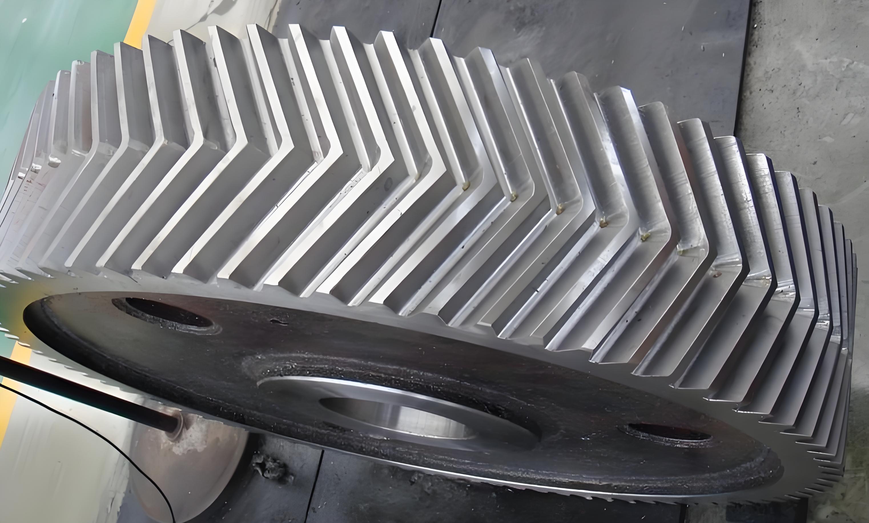
In the heart of a hot strip mill, the roughing stand’s drive train is a critical component, and at its core often lies a herringbone gear block. This sophisticated assembly is tasked with reliably transmitting immense torque from a single motor to the top and bottom work rolls. My extensive experience in maintaining such drives has revealed a persistent and costly challenge: the performance and longevity of the plain bearings, or bearing bushes, that support the herringbone gear shafts. Traditional maintenance approaches, while functional, led to excessive downtime, short bearing life, and abnormal wear patterns on the gears themselves. This article details my first-person analytical journey to understand the root causes of these failures and to develop a refined grinding and control methodology that significantly enhanced the operational stability of the herringbone gear unit.
The fundamental role of the herringbone gear block cannot be overstated. It must split power with perfect symmetry while accommodating the dynamic loads and occasional shocks inherent to the roughing process. The specific design in question utilizes a three-piece bearing housing arrangement for each shaft side, comprising an upper, middle (H), and lower seat. These housings contain cast Babbitt metal bearing bushes. A critical feature of this herringbone gear assembly is its immensely rigid, housing structure, which resembles a mill housing. This inherent stiffness, often overlooked in maintenance routines, later proved to be the foundation for our improved control strategy.
The persistent issues observed over many maintenance cycles were systematic:
- Excessive Maintenance Workload: Each overhaul required complete bearing replacement and hand-scraping. The required scraping allowance was excessively large, often over 1.5mm per side for the lower bearings and over 2.5mm for the upper ones, consuming more than 100 hours of skilled labor for a set of four bearings.
- Short and Unpredictable Bearing Life: The typical service interval was a mere 6 to 10 months. Failures consistently presented as cracking, spalling, and even detachment of the Babbitt lining, particularly in specific quadrants of the bearings.
- Gear Shaft Vibration (“Beating”): The upper gear shaft exhibited noticeable跳动, which translated into abnormal dynamic loading.
- Axial Damage to Bearing Edges: The lower shaft’s bearing bush often showed chipping and spalling at the inner edge of the lower bearing cap.
- Abnormal Gear Tooth Wear: Regular inspections revealed systematic scoring, galling, and the formation of ridges on the flanks of both herringbone gear pinions.
A detailed analysis of maintenance records and the drive’s kinematics was crucial. The problems were interlinked, stemming from an imprecise initial bearing geometry and inappropriate operational clearances.
1. Root Cause Analysis: Beyond Conventional Scraping
The traditional scraping process focused solely on achieving a good contact pattern (≥75% over 120°) and the correct contact points between the bearing and the journal. However, this process could not correct for higher-order misalignments inherited from the initial machining of the bearing housings. The key parameters identified were:
- Bearing Centerline Parallelism & Gear Center Distance: The upper and lower gear shafts must be perfectly parallel, and their center distance must be held to a tight tolerance to ensure proper herringbone gear meshing. Initial boring of the bearing housings was done independently, with no guarantee of coaxiality between the drive (D) and work (W) sides, or of correct vertical alignment between the upper and lower bearings. This misalignment is quantified as an error in parallelism and center distance.
Let the nominal center distance be \( A_0 \). The actual center distance at the drive side (D) and work side (W) can be \( A_D \) and \( A_W \). The parallelism error \( \Delta \theta \) can be derived from the difference in vertical alignment (\( \Delta h \)) over the bearing span (\( L \)):
$$\Delta \theta \approx \arctan\left(\frac{\Delta h}{L}\right)$$
Scraping cannot fix these global errors; the gears are forced to “run in” under misaligned conditions, causing the observed scoring and ridging. A correlation was evident from historical data:
| Inspection Cycle | Center Distance A_D (mm) | Center Distance A_W (mm) | Axial Scoring Length on Teeth (mm) |
|---|---|---|---|
| 1 | 1172.0 | 1170.0 | 30 / 22 |
| 2 | 1169.0 | 1171.0 | 25 / 28 |
| 3 | 1168.0 | 1170.0 | 20 / 30 |
| 4 | 1169.0 | 1170.0 | 28 / 31 |
| 5 | 1168.0 | 1169.0 | 22 / 25 |
Clearly, deviations from the nominal \( A_0 = 1168.4 \) mm correlated with increased wear.
- Radial Clearance (Top Cap): The standard rule-of-thumb for bearing clearance (\( c \)) is \( (1.0/1000 \text{ to } 1.2/1000) \times d \), where \( d \) is the journal diameter (710 mm). This gives \( c_{std} = 0.71 \text{ to } 0.85 \) mm. Analysis of records showed that when the upper bearing clearance exceeded this range, vibration and bearing damage increased. The upper herringbone gear shaft, being connected to the oscillating rolls via spindles, is more susceptible to dynamic instabilities. Excessive clearance exacerbates this, acting as a primary cause for the “beating” phenomenon and reduced bearing life.
- Axial End Clearance (Side Play): The lower herringbone gear shaft is typically the axial locating shaft. Its small axial clearance (originally 0.4mm) was insufficient to absorb the axial components of force from the oscillating roll spindles and the self-aligning nature of the herringbone gear. This resulted in repeated axial impacts of the shaft against the bearing edge, causing the characteristic chipping and spalling.
- Excessive Scraping Allowance: The large mandatory scraping amount was a symptom, not a cause. It was necessitated by the need to manually create both the correct bearing geometry and the required clearance, as the three-piece housing design precluded the use of adjustable shims under the bearing caps.
2. The Optimized Grinding and Control Methodology
The solution was built upon a paradigm shift: Precision must be built into the bearing housing during initial machining, and scraping should only be a final fine-tuning process for perfect journal contact. The rigid housing structure makes this possible, as it does not deflect significantly under load.
2.1 Establishing Precision Machining Specifications
The initial boring of all bearing housings must be done with strict positional tolerances to guarantee shaft alignment before the Babbitt is poured and scraped. The following protocol was implemented:
- Lower Shaft Bearing Bores (Both Sides): Machine the D-side and W-side lower bearing seats in a single setup. The coaxiality tolerance between these two bores must be within 0.04 mm. The machined centerline is defined as the primary datum.
- Upper Shaft Bearing Bores (Both Sides): Using the established lower shaft centerline as the datum, machine the upper bearing bores in a single setup. The vertical center distance \( A \) must be held to \( A_0 \pm 0.04 \) mm, and the coaxiality between D and W sides must also be within 0.04 mm.
This ensures that the initial condition of the bearing system provides near-perfect parallelism and correct center distance for the herringbone gear mesh.
2.2 Optimized Radial Clearance Specifications
Based on operational data, the standard clearance rule was refined differentially for the upper and lower shafts:
- Lower Gear Shaft Bearings: Maintain the traditional standard to ensure good hydrodynamic lubrication formation: \( c_{lower} = (1.0/1000)d \text{ to } (1.2/1000)d \).
- Upper Gear Shaft Bearings: Use a tighter range to control dynamic instability: \( c_{upper} = (0.8/1000)d \text{ to } (1.0/1000)d \), effectively setting \( c_{upper} \approx 0.55 \text{ to } 0.71 \) mm. This reduced clearance dampens the vibration of the more susceptible upper herringbone gear shaft.
| Parameter | Symbol | Traditional Standard | Optimized Standard | Rationale |
|---|---|---|---|---|
| Upper Shaft Radial Clearance | \(c_{upper}\) | 0.71 – 0.85 mm | 0.55 – 0.71 mm | Suppress shaft vibration/跳动 |
| Lower Shaft Radial Clearance | \(c_{lower}\) | 0.71 – 0.85 mm | 0.71 – 0.85 mm | Maintain optimal oil film |
| Lower Shaft Axial End Clearance | \(a\) | 0.4 mm | 1.0 mm | Absorb axial forces from rolls & gear meshing |
2.3 Calculating the Optimal Scraping Allowance
With the housing bores machined to precise location and size, the required scraping allowance is minimized. It is calculated geometrically to achieve the 120° contact angle and the specified top clearance \(c\). The goal is for the pre-scraped bore circle to be tangent to the final scraped profile, minimizing waste.
Let:
\(d\) = Final finished journal diameter (712 mm, after final fit).
\(c\) = Specified radial clearance (e.g., 0.71 mm for lower bearing).
\(R_1 = d/2\) = Final bearing bore radius.
\(h = c/2\) = Vertical offset of the final bore center from the split line.
The final bore circle equation relative to the split line is:
$$ x^2 + (y – h)^2 = R_1^2 $$
The chord representing the 120° contact arc has end points at \(y=0\). The contact half-angle from the vertical is 60°. The radius \(R_0\) of the initial machined bore (before scraping) should be such that its circle passes through these endpoints. The y-coordinate of these endpoints on the final circle is 0, the x-coordinate is:
$$ x_{end} = \sqrt{R_1^2 – h^2} $$
This \(x_{end}\) is the same for the initial circle centered at (0,0). Therefore, the initial radius \(R_0\) equals \(x_{end}\):
$$ R_0 = \sqrt{R_1^2 – h^2} $$
The optimal radial scraping allowance \(\delta_r\) is then:
$$ \delta_r = R_1 – R_0 = R_1 – \sqrt{R_1^2 – h^2} $$
Substituting \(h = c/2\):
$$ \delta_r = \frac{d}{2} – \sqrt{\left(\frac{d}{2}\right)^2 – \left(\frac{c}{2}\right)^2} $$
For \(d = 712\) mm and \(c = 0.71\) mm (lower bearing):
$$ \delta_r \approx 356 – \sqrt{356^2 – 0.355^2} \approx 356 – \sqrt{126736 – 0.126} \approx 356 – 355.9998 \approx 0.0002 \text{ m} = 0.2 \text{ mm} $$
This is the theoretical minimum. In practice, a slightly larger allowance of 0.3 mm is specified for the initial bore diameter to account for imperfections and to allow for the formation of oil pockets at the edges. This is a drastic reduction from the previous 1.5-2.5 mm, cutting scraping time by over 60%.
| Bearing | Journal Dia. \(d\) (mm) | Clearance \(c\) (mm) | Theoretical Allowance \( \delta_r \) (mm) | Practical Initial Bore Dia. (mm) | Practical Allowance (mm) |
|---|---|---|---|---|---|
| Upper | 712 | 0.63 (avg) | ~0.14 | 711.4 ±0.4 | 0.3 |
| Lower | 712 | 0.71 | ~0.20 | 711.4 ±0.4 | 0.3 |
2.4 Determining the Axial End Clearance
Empirical testing with different axial clearances (\(a\)) for the locating lower shaft showed that a clearance of 1.0 mm provided the best compromise. It was sufficient to prevent damaging impacts against the bearing edge while minimizing excessive axial float that could affect the herringbone gear meshing stability.
3. Results and Broader Implications
Implementing this controlled methodology—precision machining, optimized clearances, and minimal scraping—yielded transformative results for the herringbone gear drive:
- Bearing Life: Increased from 6-10 months to over 24 months.
- Maintenance Workload: Scraping time reduced from >100 hours to approximately 40 hours per set.
- Gear Meshing: Abnormal wear patterns (scoring, ridging) were virtually eliminated due to the correct, preset gear center distance and parallelism.
- Operational Stability: Shaft vibration was significantly dampened, leading to smoother operation and reduced noise.
- Bearing Failure Mode: The chronic failure modes (cracking, spalling at specific locations) were no longer observed.
| Performance Metric | Traditional Method | Optimized Control Method | Improvement |
|---|---|---|---|
| Mean Time Between Overhauls (MTBO) | 8 months | >24 months | >300% |
| Bearing Scraping Labor Hours | >100 hours | ~40 hours | ~60% reduction |
| Incidence of Gear Tooth Scoring | High / Regular | Very Low / None | Eliminated |
| Upper Shaft Vibration Level | High | Low / Normal | Significantly Reduced |
4. Theoretical Extension and General Principles
The success of this approach hinges on recognizing the herringbone gear block as a system where bearing alignment is paramount. The general principles derived can be expressed for similar applications:
- System Stiffness is a Prerequisite: The method assumes a rigid housing. The bearing alignment achieved during machining must be preserved under operational loads. The formula for relative displacement \( \Delta \) under load \( F \) is \( \Delta = F/K \), where \( K \) is the system stiffness. For this to be negligible, \( K \) must be very high.
- Clearance as a Dynamic Parameter: Radial clearance \(c\) is not just a lubrication parameter but a key dynamic stabilizer. For shafts susceptible to external excitation (like the upper herringbone gear shaft), a reduced clearance \(c_{opt}\) can be modeled as a function of the expected excitation frequency \( \omega_{ex} \) and the shaft’s natural frequency \( \omega_n \):
$$ c_{opt} \propto \frac{1}{\sqrt{|\omega_{ex}^2 – \omega_n^2|}} $$
A tighter clearance increases the effective damping ratio. - Alignment Error and Gear Mesh: Any parallelism error \( \Delta \theta \) or center distance error \( \Delta A \) induces a cyclical transmission error \( \Delta TE \) in the herringbone gear mesh, a primary source of vibration and wear:
$$ \Delta TE \approx \Delta A \cdot \sin(\beta) + \Delta \theta \cdot L_{eff} \cdot \cos(\beta) $$
where \( \beta \) is the helix angle and \( L_{eff} \) is an effective length. Controlling \( \Delta A \) and \( \Delta \theta \) at the bearing level directly minimizes \( \Delta TE \).
In conclusion, the chronic problems associated with the bearing bushes in a double-reduction herringbone gear block were not merely issues of scraping skill or material quality. They were systemic issues stemming from imprecise initial geometry and suboptimal operational parameters. By shifting the focus to precision machining of the bearing housings to guarantee shaft alignment, scientifically defining clearances based on shaft dynamics, and minimizing the scraping process to its essential role of final fitting, the reliability and performance of the entire herringbone gear drive were dramatically improved. This methodology, leveraging the inherent stiffness of the gear housing, provides a robust framework for the maintenance and control of similar high-power, critical herringbone gear drives in rolling mills and other heavy industries.