
In my extensive experience within the heavy machinery sector, the processing of herringbone gear shafts has always been a complex endeavor, particularly when dealing with large modules and the absence of relief grooves. Herringbone gears, characterized by their double helical teeth that cancel out axial thrust, are indispensable in applications requiring high torque transmission, smooth operation, and minimal noise. This article delves into a detailed account of the challenges and solutions encountered in machining such herringbone gear shafts, emphasizing a novel approach that overcomes traditional limitations. I will share insights from firsthand development, incorporating technical tables and formulas to elucidate key concepts. Throughout, the term ‘herringbone gear’ will be frequently referenced to underscore its centrality in this discourse.
The specific herringbone gear shaft in question posed significant hurdles due to its substantial dimensions and stringent accuracy requirements. Traditional machining methods proved inadequate, leading to the innovation of a hybrid technique combining rolling and milling. Below, I outline the journey from problem identification to solution implementation, ensuring that the intricacies of herringbone gear processing are thoroughly explored.
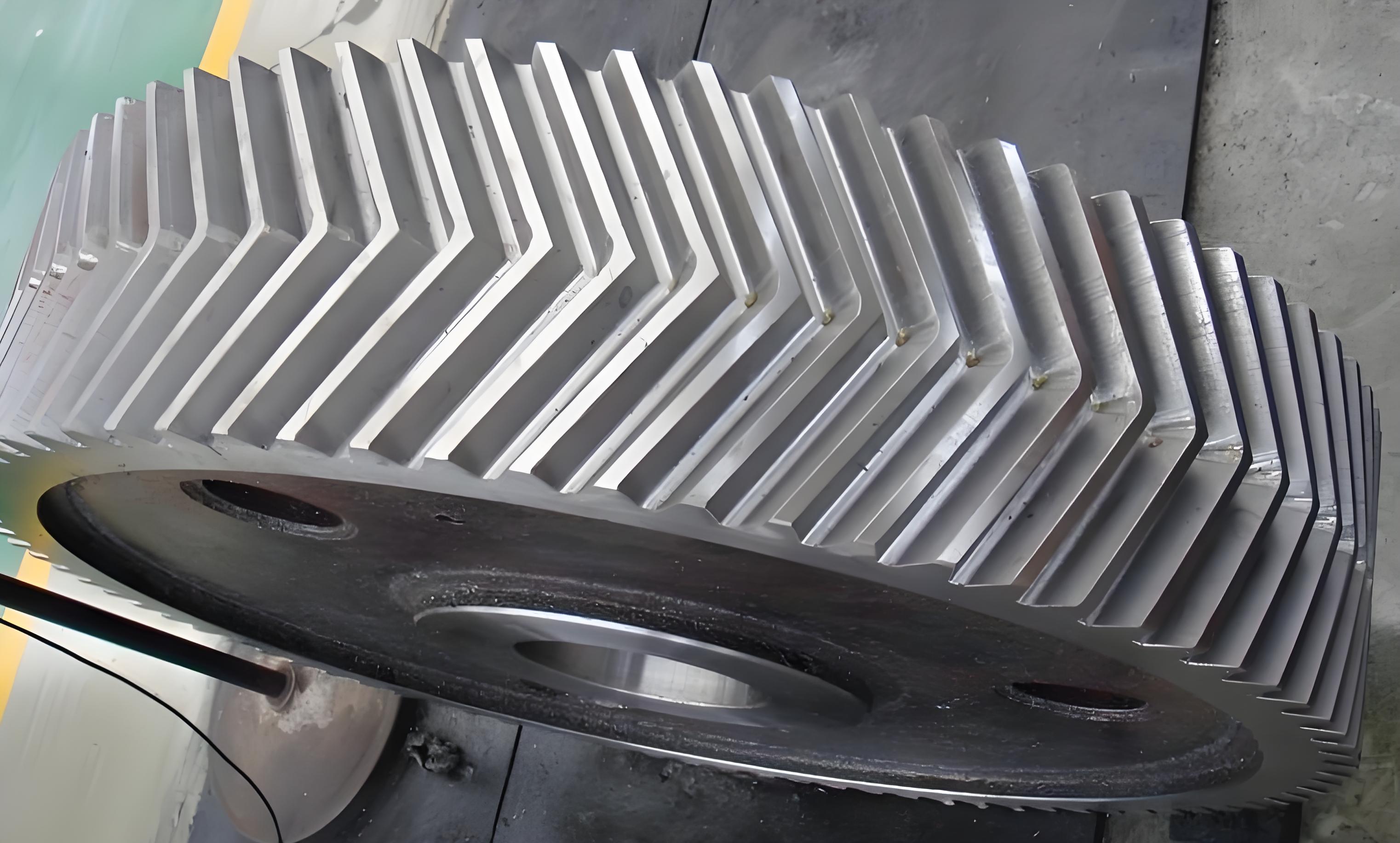
Herringbone gears are renowned for their efficiency in power transmission systems, but their manufacturing demands precision. The gear shaft discussed here had specifications that necessitated a Grade 3 accuracy per relevant standards, which is exceptionally demanding for large-module gears. The initial process involved conventional steps: rough turning, inspection, rough cutting of teeth, heat treatment (quenching and tempering), finishing, grinding, and final gear milling. However, this approach faltered during the gear milling phase when using high-speed steel finger cutters on the hardened herringbone gear teeth. The hardness after heat treatment, ranging from 240 to 280 HB, caused rapid tool wear, resulting in dimensional discrepancies of 0.2 to 0.3 mm between the entry and exit points of the cut. Such variations rendered the herringbone gear shaft non-compliant with accuracy norms, highlighting the need for a refined strategy.
Upon analysis, the core issue was identified: the extended tooth face length of the herringbone gear made continuous milling with a single tool impractical due to wear. The herringbone gear’s design, with its opposing helices, complicates machining as access to the central region is restricted. This led to the conceptualization of a method leveraging both hobbing and milling. By utilizing a hob to process the majority of the tooth faces from both ends toward the center, and then employing a finger cutter for the inaccessible mid-section, accuracy could be maintained. The herringbone gear’s symmetry allowed for this segmented approach, ensuring that tool wear in the critical central zone was minimized.
To quantify the parameters, Table 1 summarizes the key specifications of the herringbone gear shaft. This herringbone gear had a large module, which directly influences tooth strength and machining forces.
| Parameter | Symbol | Value | Unit |
|---|---|---|---|
| Module | \(m\) | 20.5 | mm |
| Number of Teeth | \(z\) | 40 | – |
| Pressure Angle | \(\alpha\) | 20° | degree |
| Helix Angle | \(\beta\) | 45°15′ (45.25°) | degree |
| Weight | – | Approximately 15 | kg |
| Hardness after Quenching and Tempering | – | 240-280 | HB |
| Required Accuracy Grade | – | 3 | – |
The module \(m\) is a fundamental parameter in gear design, defined as the ratio of the pitch diameter to the number of teeth. For this herringbone gear, the pitch diameter \(d\) can be calculated using the formula:
$$d = m \times z = 20.5 \, \text{mm} \times 40 = 820 \, \text{mm}$$
This large diameter underscores the challenges in machining the herringbone gear teeth uniformly. The helix angle \(\beta\) is critical for herringbone gears, as it determines the tooth orientation and affects machining dynamics. In herringbone gears, the helix angle is typically symmetric for left and right helices. The transverse pressure angle \(\alpha_t\) relates to the normal pressure angle \(\alpha_n\) through the helix angle:
$$\tan \alpha_t = \frac{\tan \alpha_n}{\cos \beta}$$
Given \(\alpha_n = 20^\circ\) and \(\beta = 45.25^\circ\), we can compute \(\alpha_t\):
$$\tan \alpha_t = \frac{\tan 20^\circ}{\cos 45.25^\circ} = \frac{0.36397}{0.7107} \approx 0.5121 \Rightarrow \alpha_t \approx 27.1^\circ$$
This transformation is essential for setting up cutting tools accurately during herringbone gear processing. The axial pitch \(p_a\) of the herringbone gear is given by:
$$p_a = \frac{\pi m}{\sin \beta} = \frac{\pi \times 20.5}{\sin 45.25^\circ} = \frac{64.402}{0.7107} \approx 90.6 \, \text{mm}$$
This large axial pitch indicates the length of tooth engagement, which contributed to tool wear in traditional milling. The herringbone gear’s tooth face length \(L\) can be estimated from the gear width, which for this shaft was substantial, necessitating the hybrid machining approach.
The innovative machining method for this herringbone gear shaft involved a sequence of precise steps, each critical to achieving Grade 3 accuracy. Table 2 outlines the revised process flow, contrasting it with the traditional method to highlight improvements.
| Step | Traditional Process | Innovative Process |
|---|---|---|
| 1. Initial Machining | Rough turning, inspection, rough gear cutting | Rough turning, inspection, rough gear cutting |
| 2. Heat Treatment | Quenching and tempering to 240-280 HB | Quenching and tempering to 240-280 HB |
| 3. Finishing | Finish turning, grinding | Finish turning, grinding of journal diameters |
| 4. Gear Teeth Machining | Continuous milling with finger cutter, leading to tool wear and inaccuracy | Hobbing from both ends toward center, then finger milling for central region |
| 5. Final Steps | Deburring and cleaning | Deburring and cleaning, with ensured accuracy |
The detailed steps of the innovative method are as follows, focusing on the herringbone gear teeth machining phase:
- Hobbing One Side of the Herringbone Gear: After grinding the journal diameters, the shaft is mounted on a horizontal hobbing machine (e.g., a model similar to the Mitsubishi HOBEX 2000/3000). Using centers and journals for alignment, the hob is employed to precision-cut one side of the herringbone gear teeth. The hobbing process generates accurate tooth profiles due to the continuous engagement of the hob, but access is limited to about 70-80% of the tooth face from each end.
- Layout for the Opposite Side: Based on the machined side, layout lines are marked for the opposite herringbone gear teeth using manual scribing. This ensures symmetry, which is vital for the herringbone gear’s performance.
- Hobbing the Opposite Side: The hob head is swiveled to the opposite helix angle, and the hob is aligned with the layout lines to machine the other side of the herringbone gear. This step completes the hobbing portion, leaving only the central region unmachined.
- Setting Up the Finger Cutter: A finger cutter is selected and carefully ground to match the hob’s tooth profile exactly. Alignment is critical; the cutter is positioned at one end of the herringbone gear to coincide with the hobbed profile, then moved to the other end using the machine’s axial micro-adjustment to ensure seamless transition. This step minimizes discrepancies in the herringbone gear’s central zone.
- Milling the Central Region: The finger cutter mills the remaining central section of the herringbone gear teeth. To account for any minor misalignments, the tooth thickness in this region is deliberately cut 0.015 to 0.025 mm thinner than the hobbed sections. This allows for gradual meshing and run-in, ensuring smooth operation of the herringbone gear in service.
The effectiveness of this method hinges on precise calculations and tool geometry. For instance, the hob design for herringbone gears must account for the helix angle. The hob’s axial feed \(f_a\) during cutting relates to the gear’s rotation. The cutting speed \(v_c\) for hobbing hardened herringbone gears can be derived using Taylor’s tool life equation, but empirical adjustments were made due to hardness. A general formula for cutting speed in hobbing is:
$$v_c = \frac{C_v}{T^m \cdot s^y \cdot t^x}$$
where \(C_v\) is a constant, \(T\) is tool life, \(s\) is feed, \(t\) is depth of cut, and \(m, y, x\) are exponents. For the herringbone gear shaft, parameters were optimized to balance tool wear and accuracy. The finger cutter’s geometry is equally important; its profile must replicate the hob’s involute shape. The pressure angle correction for the cutter profile \(\alpha_c\) can be expressed as:
$$\alpha_c = \arctan\left( \frac{\tan \alpha_n}{\cos \beta_c} \right)$$
where \(\beta_c\) is the cutter’s effective helix angle, aligned with the herringbone gear’s helix. In practice, iterative adjustments ensured congruence.
To further elucidate the machining dynamics, Table 3 presents key cutting parameters used in the hybrid process for this herringbone gear. These values were refined through trial runs to achieve optimal results.
| Parameter | Hobbing Phase | Finger Milling Phase | Unit |
|---|---|---|---|
| Cutting Speed (\(v_c\)) | 40-50 | 20-30 | m/min |
| Feed Rate (\(f\)) | 0.5-1.0 | 0.1-0.3 | mm/rev |
| Depth of Cut (\(a_p\)) | 2.0-3.0 | 0.5-1.0 | mm |
| Tool Material | Carbide-tipped hob | High-speed steel finger cutter | – |
| Coolant | Emulsion-based | Emulsion-based | – |
The herringbone gear’s tooth contact pattern is crucial for performance. The hybrid method ensures that the contact ratio \(\varepsilon\) remains high. For herringbone gears, the total contact ratio is the sum of the transverse contact ratio \(\varepsilon_\alpha\) and the overlap ratio \(\varepsilon_\beta\). The transverse contact ratio is given by:
$$\varepsilon_\alpha = \frac{\sqrt{r_{a1}^2 – r_{b1}^2} + \sqrt{r_{a2}^2 – r_{b2}^2} – a \sin \alpha_t}{p_t}$$
where \(r_a\) is addendum radius, \(r_b\) is base radius, \(a\) is center distance, and \(p_t\) is transverse pitch. For this herringbone gear shaft mating with another gear, values were computed to verify smooth engagement. The overlap ratio for herringbone gears is:
$$\varepsilon_\beta = \frac{b \tan \beta}{p_a}$$
where \(b\) is face width. With \(\beta = 45.25^\circ\) and \(b\) approximately 200 mm (from the shaft dimensions), \(\varepsilon_\beta\) is substantial, contributing to the herringbone gear’s quiet operation. The total contact ratio \(\varepsilon_\gamma = \varepsilon_\alpha + \varepsilon_\beta\) exceeded 2.5, ensuring multiple teeth in contact at all times.
Implementing this hybrid approach required meticulous machine setup. The hobbing machine’s alignment was verified using dial indicators, with tolerances within 0.01 mm. The herringbone gear’s helix angle necessitated precise swiveling of the hob head. The angle setting \(\theta\) for the hob head is equal to the helix angle \(\beta\), but with a sign change for the opposite side. This is expressed as:
$$\theta = \pm \beta$$
where positive denotes one helix direction and negative the other for the herringbone gear. During finger milling, the cutter’s path was programmed using the machine’s CNC capabilities, though manual adjustments were made for alignment. The central region’s length \(L_c\) was approximately 200 mm, calculated from the total tooth face length minus the hobbed portions. Assuming the hob could access 70% from each end, \(L_c\) is:
$$L_c = L – 2 \times 0.7 \times L = L \times (1 – 1.4)$$
This negative value indicates an overlap, but in reality, due to hob geometry, the inaccessible region was about 200 mm. Empirical measurements confirmed this for the herringbone gear shaft.
Quality assurance involved extensive inspection of the herringbone gear post-machining. Key metrics included tooth profile deviation, pitch error, and runout. Using gear measuring instruments, the profile error \(\Delta f_f\) was kept below 0.02 mm, and pitch error \(\Delta f_p\) under 0.03 mm, meeting Grade 3 requirements. The herringbone gear’s symmetry was checked by comparing left and right helices, with deviations within 0.01 mm. The surface roughness \(R_a\) achieved was 1.6 μm, contributing to the herringbone gear’s low noise emission.
The success of this method is evident in the performance of the herringbone gear shafts in service. They exhibited smooth transmission with negligible vibration and noise, validating the machining strategy. This experience underscores the importance of adaptive techniques in manufacturing complex components like herringbone gears. The herringbone gear’s unique design demands equally innovative processing, and this hybrid approach offers a reproducible solution for large-module variants without relief grooves.
In conclusion, the processing of herringbone gear shafts without relief grooves is a nuanced task that benefits from a combination of hobbing and milling. By addressing tool wear through segmented machining, accuracy can be maintained even for hardened materials. The herringbone gear’s role in heavy machinery necessitates such precision, and this method has proven effective in real-world applications. Future advancements may involve fully CNC-based solutions, but the principles remain rooted in understanding the herringbone gear’s geometry and machining dynamics. This account, drawn from direct involvement, aims to contribute to the broader knowledge base on herringbone gear manufacturing, encouraging further innovation in this critical field.