
The evolution of mechanical design has been profoundly accelerated by the integration of Computer-Aided Design (CAD) technologies. Among various mechanical components, gear transmissions hold a paramount position due to their efficiency, reliability, and capacity for precise power transmission. The herringbone gear, a specialized double-helical gear with left-hand and right-hand helices meeting at a central point, offers distinct advantages over its single-helical counterpart. Primarily, it inherently cancels out axial thrust forces, eliminating the need for complex thrust bearings and allowing for simpler, more robust shaft and bearing arrangements. This makes the herringbone gear exceptionally suitable for high-power, high-torque applications such as ship propulsion systems, heavy-duty industrial gearboxes, and turbine drives. However, the complex three-dimensional geometry of a herringbone gear presents significant challenges in manual design and drafting, making it an ideal candidate for sophisticated CAD and parametric modeling techniques.
The core of modern mechanical CAD transcends simple electronic drafting. It involves the creation of intelligent, rule-driven models where geometry is controlled by parameters and constraints. This paradigm, known as parametric design, is revolutionary. For a component like a herringbone gear, it means that fundamental design variables—module, number of teeth, helix angle, face width—become the primary inputs. Altering any of these parameters automatically triggers a cascade of recalculations (for strength, geometry, etc.) and regenerates the associated 2D drawing and 3D model. This approach not only drastically reduces design time and minimizes human error but also facilitates design optimization, variant creation, and provides a seamless link to Computer-Aided Manufacturing (CAM) and Finite Element Analysis (FEA) software. The development of a dedicated CAD system for herringbone gear design, therefore, involves intertwining mechanical design theory, software engineering, and interactive user interface design.
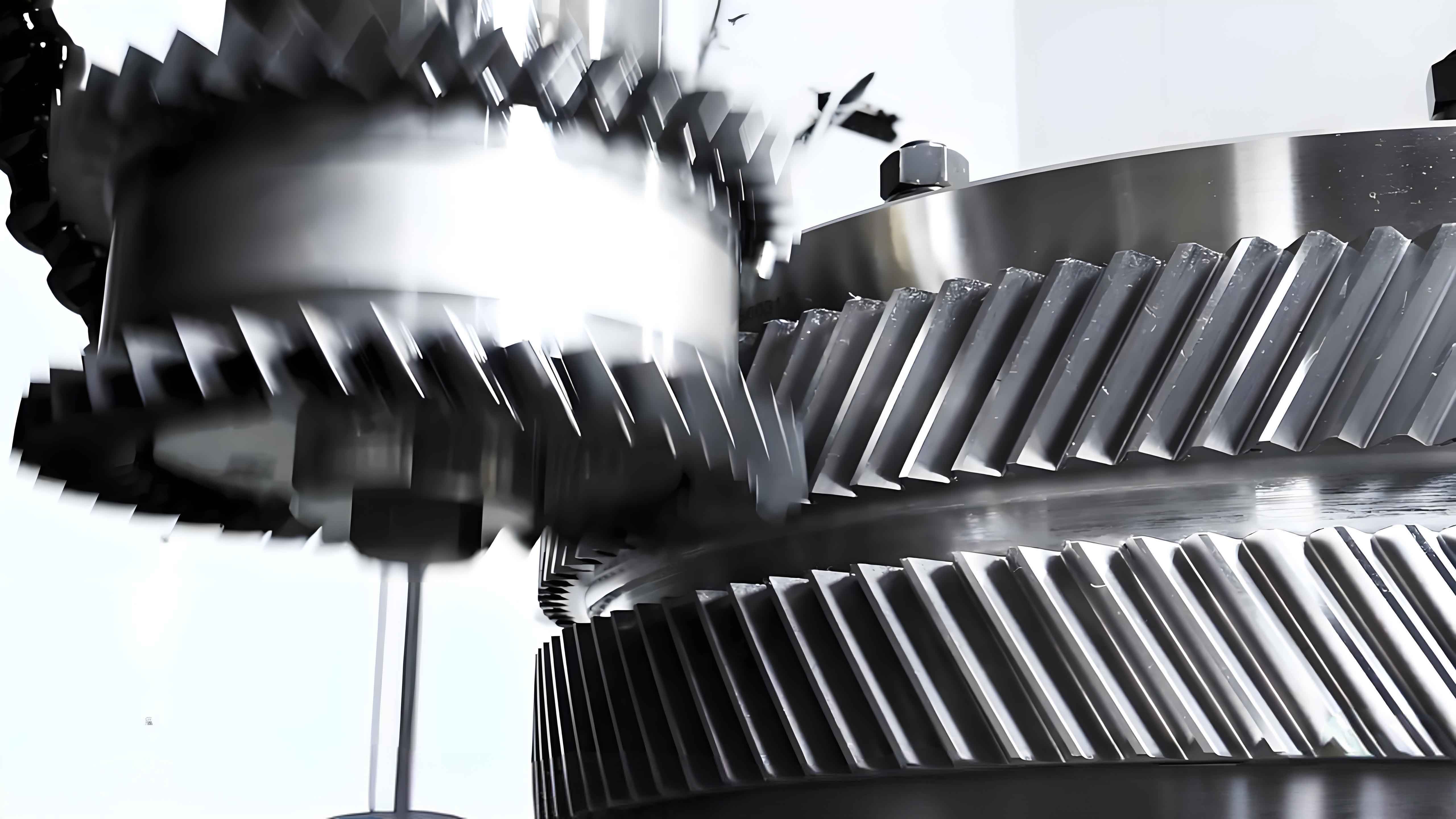
The visual representation above clearly illustrates the unique double-helical structure of the herringbone gear, highlighting the V-shaped groove at the center where the two helices meet. This geometry is central to its function and a key focus of parametric modeling.
Fundamental Design Theory and Calculations for Herringbone Gears
The design process for a herringbone gear pair is governed by standardized mechanical engineering principles, primarily derived from standards like AGMA (American Gear Manufacturers Association) or ISO (International Organization for Standardization). The initial phase involves selecting primary design parameters based on functional requirements: transmitted power (P), input speed (n1), desired gear ratio (i), and application-specific factors (shock load, desired life).
The core geometric parameters defining a herringbone gear are interrelated through a set of fundamental equations. The normal module (m_n) is often the starting point for sizing. The transverse module (m_t), which governs the geometry in the plane of rotation, is related to the normal module and the helix angle (β) by:
$$m_t = \frac{m_n}{\cos\beta}$$
The pitch diameters (d) for the pinion (1) and gear (2) are calculated using the number of teeth (Z) and the transverse module:
$$d_1 = Z_1 \cdot m_t, \quad d_2 = Z_2 \cdot m_t = Z_1 \cdot i \cdot m_t$$
The center distance (a), a critical housing dimension, is:
$$a = \frac{d_1 + d_2}{2} = \frac{m_t (Z_1 + Z_2)}{2} = \frac{m_n (Z_1 + Z_2)}{2\cos\beta}$$
The total face width (b) is the sum of the widths of the two helical halves. For a symmetric herringbone gear, each half has a width of approximately b/2.
Beyond geometry, strength calculation is paramount. The design must ensure that the gears can withstand the applied loads without failure from bending at the tooth root or pitting on the tooth flank. The bending stress (σ_F) and contact stress (σ_H) are calculated using standardized load capacity equations. For a herringbone gear, these calculations typically consider the load on a single helical plane, though standards provide methods to account for the double-helical configuration. The basic bending stress equation for a spur gear is adapted with factors for helix angle, face width, and load sharing between the two helices:
$$\sigma_F = \frac{F_t}{b \cdot m_n} \cdot Y_F \cdot Y_S \cdot Y_\beta \cdot K_A \cdot K_V \cdot K_{F\beta} \cdot K_{F\alpha}$$
Where:
– $F_t$ is the tangential load.
– $Y_F$ is the tooth form factor.
– $Y_S$ is the stress correction factor.
– $Y_\beta$ is the helix angle factor.
– $K_A$, $K_V$, $K_{F\beta}$, $K_{F\alpha}$ are application, dynamic, face load, and transverse load factors, respectively.
The contact stress (pitting resistance) is given by:
$$\sigma_H = Z_H \cdot Z_E \cdot Z_\epsilon \cdot Z_\beta \cdot \sqrt{\frac{F_t}{d_1 \cdot b} \cdot \frac{u+1}{u} \cdot K_A \cdot K_V \cdot K_{H\beta} \cdot K_{H\alpha}}$$
Where:
– $Z_H$ is the zone factor.
– $Z_E$ is the elasticity factor.
– $Z_\epsilon$ is the contact ratio factor.
– $Z_\beta$ is the helix angle factor for contact stress.
– $u$ is the gear ratio ($Z_2/Z_1$).
These calculated stresses are then compared to the allowable bending fatigue strength ($\sigma_{FP}$) and allowable contact fatigue strength ($\sigma_{HP}$) of the gear material, incorporating safety factors ($S_F$, $S_H$):
$$\sigma_F \leq \frac{\sigma_{FP}}{S_F}, \quad \sigma_H \leq \frac{\sigma_{HP}}{S_H}$$
This iterative process of selecting parameters, calculating geometry, checking stresses, and adjusting parameters forms the algorithmic core of any herringbone gear CAD system. The table below summarizes the key input parameters and typical output checks in the design process.
| Category | Primary Input Parameters | Calculated Geometric Outputs | Critical Design Checks |
|---|---|---|---|
| Power & Kinematics | Power (P), Input Speed (n1), Gear Ratio (i) | Output Speed (n2), Torques (T1, T2) | Service Factor (K_A) |
| Material & Life | Material Grade, Heat Treatment, Design Life | Allowable Stresses (σ_FP, σ_HP) | Safety Factors (S_F, S_H) |
| Geometry Definition | Normal Module (m_n), Teeth (Z1, Z2), Helix Angle (β), Face Width (b) | Pitch Diameters (d1, d2), Center Distance (a), Tip/Root Diameters | Undercut Avoidance, Contact Ratio |
| Load & Strength | Application Factors (Shock, Reliability) | Tangential Load (F_t), Bending Stress (σ_F), Contact Stress (σ_H) | σ_F ≤ σ_FP/S_F , σ_H ≤ σ_HP/S_H |
Architecture of a Herringbone Gear CAD System
Building a functional CAD system for herringbone gear design requires a structured software architecture that seamlessly integrates calculation engines, user interaction, and graphical output. A robust architecture typically follows a modular approach, separating concerns for maintainability and scalability. The system’s workflow can be conceptualized in a logical progression from user input to final technical documentation.
The process begins with the User Interface (UI) Module, which is responsible for all human-computer interaction. For a system built on a platform like AutoCAD, this often involves creating custom dialog boxes using a language like DCL (Dialog Control Language) or newer .NET frameworks. These dialog boxes guide the user through a structured input sequence: first setting the design environment (units, standards), then entering the fundamental power, speed, ratio, and material data, and finally defining the initial geometric guesses for the herringbone gear. A well-designed UI prevents invalid inputs, provides tooltips, and makes the design process intuitive.
Once inputs are validated, control passes to the Core Calculation Engine. This is the heart of the system, implemented in a programming language like AutoLISP, Visual Basic for Applications (VBA), or ObjectARX/.NET for AutoCAD. This module contains all the algorithms for:
1. Preliminary geometry calculation (diameters, center distance).
2. Load and force analysis.
3. Detailed strength calculation based on selected standards (AGMA, ISO), iterating through bending and pitting formulas.
4. Checking safety factors and design constraints (e.g., minimum contact ratio).
If a check fails, the engine must have logic to suggest parameter adjustments (e.g., increase module, increase face width, select stronger material) and re-calculate. This may involve several automated iteration loops before converging on a valid design for the herringbone gear.
Following successful calculations, the Data Management Module organizes the results. It stores all input parameters, calculated values, iteration histories, and final valid data set in a structured format, often within the CAD drawing’s extended data or in an external file. This data set is then ready for the downstream modules.
The Drawing Generation Module automates the creation of 2D production drawings. Using the finalized parameters from the data module, it executes a series of parametric drawing commands. It sets up layers, draws the front, side, and section views of the herringbone gear, details the tooth profile in a magnified view, and creates the central “V” groove section. It automatically places all necessary dimensions, geometric tolerances, and surface finish symbols. Finally, it populates the title block and a comprehensive parameters table on the drawing sheet.
Optionally, an advanced system includes a 3D Model Generation Module. Using the same parameter set, this module constructs a precise 3D solid model of the herringbone gear using Boolean operations, helical sweep, or lofting features. This model is invaluable for assembly interference checks, rendering, and as a direct input for CAM or FEA software. The entire system flow ensures that any change to a core parameter automatically updates calculations, drawings, and 3D models, embodying the true principle of associative parametric design for the herringbone gear.
| System Module | Primary Function | Key Technologies/Formats |
|---|---|---|
| User Interface (UI) | Acquire and validate design inputs via dialog boxes. | DCL, .NET Windows Forms, WPF |
| Core Calculation Engine | Perform iterative geometry and strength calculations. | AutoLISP, VBA, .NET (C#/VB.NET) |
| Data Management | Store and manage all input/output parameters. | XDATA, External XML/JSON files, Databases |
| 2D Drawing Generation | Parametrically create dimensioned orthographic views. | AutoCAD ActiveX API, .NET API |
| 3D Model Generation | Create associative 3D solid models. | AutoCAD 3D Solids API, Inventor API |
Implementation: Parametric Design with AutoLISP and DCL
The implementation of a herringbone gear CAD system within the AutoCAD environment can be effectively demonstrated using AutoLISP and DCL. AutoLISP, a dialect of the LISP programming language, is deeply integrated into AutoCAD, allowing direct access to and manipulation of drawing entities and the command line. DCL is used to define the dialog box interfaces. The development follows a sequence: designing the dialog, writing the LISP logic for calculations and drawing, and finally integrating them.
The first step is designing the user interaction flow with DCL. A typical main dialog for a herringbone gear designer would contain multiple clustered sections: a “Power & Kinematics” section with edit boxes for power, speed, and ratio; a “Material Data” section with pop-up lists for material grade and treatment; a “Gear Geometry” section for module, teeth, helix angle, and face width; and a cluster of action buttons (“Calculate”, “Draw”, “Exit”). The DCL code defines these tiles, their labels, their initial values, and their alignment. For example, a snippet for a gear ratio input might look like:
// DCL Snippet for Gear Ratio Input
: edit_box {
    key = "input_ratio";
    label = "Gear Ratio (i):";
    edit_width = 10;
    value = "4.0";
}
Separate DCL files can be created for auxiliary dialogs, such as a results display dialog that shows calculated stresses and safety factors, or a drawing setup dialog for selecting a standard title block and scale.
The core logic resides in the AutoLISP program. The main function, often named something like C:HERGEAR to make it a callable command, loads the DCL file and displays the dialog. It uses callback functions (action expressions) associated with each button. When the user clicks “Calculate”, the corresponding action function is triggered. This function performs the following steps:
- Retrieves all values from the dialog’s input tiles using
(get_tile). - Converts these text strings to numbers and validates them (e.g., positive numbers, reasonable helix angle between 15° and 35° for a herringbone gear).
- Executes the sequence of design calculations using the formulas described earlier. This involves loops for iterative refinement. The code might look like this in part:
;; AutoLISP Snippet for Preliminary Calculation
(setq m_t (/ m_n (cos (beta_rad)))) ; Transverse module
(setq d_p (* Z_p m_t))              ; Pinion pitch diameter
(setq d_g (* Z_g m_t))              ; Gear pitch diameter
(setq a (/ (+ d_p d_g) 2.0))        ; Center distance
(setq F_t (/ (* 2000 T_p) d_p))     ; Tangential force (N), T_p in Nm
;; ... Proceed to stress calculations ...
- Checks the calculated stresses against allowable limits. If the check fails, it updates dialog tiles with suggested new values (e.g., a larger module) and may even automatically re-run the calculation in a loop until a feasible design for the herringbone gear is found.
- Populates the results dialog or output tiles with the final successful design parameters, stresses, and safety factors.
Upon a successful calculation, the “Draw” button’s action function is enabled. This function uses the now-validated and calculated parameters stored in global or local variables to generate the drawing. It employs standard AutoCAD commands via the (command) function, but parametrically. For instance, the center points, radii, and angles for the gear blank are all computed from the parameters, not hard-coded. The program draws circles for the root, pitch, and tip diameters, constructs the helical tooth profiles using calculated points or splines, mirrors them to create the opposite helix, and details the central groove. It then switches to a layout, inserts a title block, creates viewports, and places all dimensions. The entire drawing is generated automatically, ensuring perfect consistency with the calculation data for that specific herringbone gear design.
Advantages, Applications, and Future Directions
The implementation of a parametric CAD system for herringbone gear design yields transformative advantages. Firstly, it dramatically enhances design efficiency. Tasks that might take hours or days for a skilled drafter—performing iterative calculations, consulting tables, and manually drawing complex tooth forms—are reduced to minutes. The designer inputs functional requirements, and the system handles the tedious computations and drafting. Secondly, it significantly improves design accuracy and consistency. Human errors in calculation, transcription, or drawing are minimized as the entire process is automated from a single source of parameters. This leads to more reliable and safer gear designs. Thirdly, it enables rapid design exploration and optimization. Engineers can effortlessly create multiple variants of a herringbone gear by changing a few key inputs (e.g., comparing 25° vs. 30° helix angles for efficiency and noise) and instantly evaluate their impact on size, weight, and strength. Finally, it establishes a direct digital thread. The parameter set can be exported to generate CNC machining G-codes, used to drive additive manufacturing processes, or serve as the basis for simulation models (FEA for stress analysis, CFD for lubrication studies), thereby integrating design, analysis, and manufacturing.
The applications of such a dedicated system are primarily in industries that utilize heavy-duty power transmission. The marine industry uses large herringbone gear sets in the reduction gearboxes between turbines or diesel engines and propeller shafts. In power generation, they are found in gearboxes connecting steam or gas turbines to generators. Heavy rolling mills in the metal industry and large extruders in plastics processing also rely on the high torque capacity and stability of herringbone gear trains. A specialized CAD system standardizes and accelerates the design process across these sectors.
Looking forward, the development of herringbone gear CAD systems is poised to evolve in several key directions. Integration with Advanced Platforms: Moving beyond basic AutoLISP to fully leverage modern .NET APIs or developing plug-ins for more advanced 3D CAD platforms like Autodesk Inventor, SolidWorks, or Siemens NX will provide more powerful 3D modeling and assembly capabilities. Cloud-Based and AI-Enhanced Design: Systems could leverage cloud computing for intensive optimization algorithms (e.g., genetic algorithms to find the lightest-weight gear meeting all constraints). Machine learning models could be trained on historical design data to suggest optimal starting parameters or predict potential failure modes. Enhanced Simulation Integration: Tight, bidirectional coupling with FEA and multi-body dynamics software would allow for real-time design validation. Changing a parameter in the CAD system could automatically update and re-run a simulation, providing immediate feedback on performance metrics like transmission error, root stress concentration, or gear mesh efficiency. Standardization and Knowledge Capture: These systems become vessels for corporate and industry knowledge, encoding best practices, material databases, and manufacturing constraints directly into the design logic, ensuring that every herringbone gear designed conforms to the highest applicable standards.
In conclusion, the parametric computer-aided design of herringbone gear systems represents a mature and highly effective application of digital engineering principles. By combining rigorous mechanical theory with robust software development practices, it transforms a complex design challenge into a streamlined, reliable, and optimized process. The continuous advancement of these systems, integrating cutting-edge computing technologies, promises to further unlock performance, reliability, and innovation in the critical field of high-power gear transmission, solidifying the role of the herringbone gear in demanding mechanical applications for the foreseeable future.