
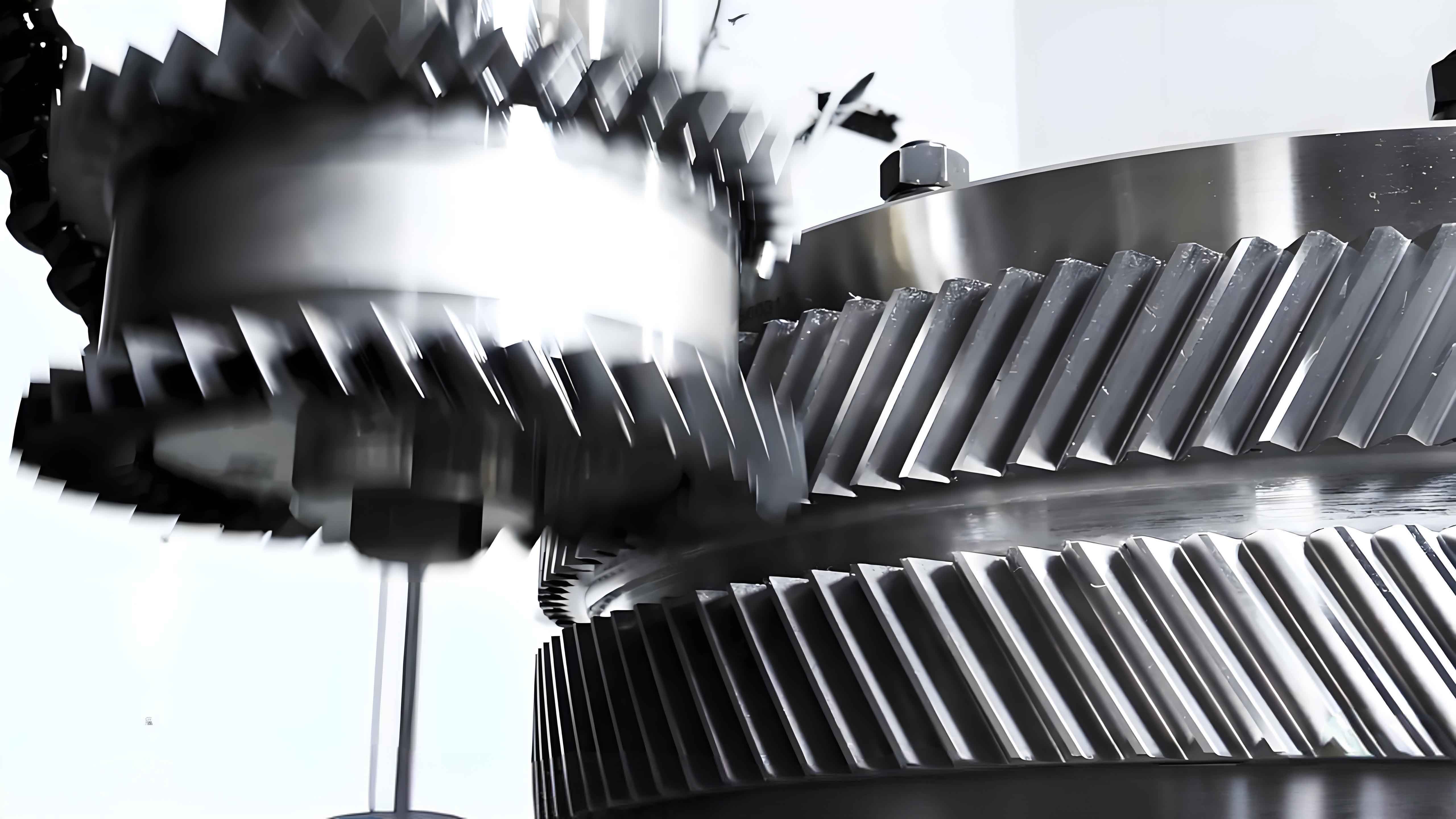
In the field of power transmission, the quest for components that offer high torque capacity, compactness, and smooth operation is perpetual. Among the various gear types, the herringbone gear stands out due to its unique double-helical design. This configuration essentially consists of two mirror-image helical gears placed side-by-side. The primary advantage of this arrangement is the inherent cancellation of axial thrust forces generated by each helix. This eliminates the need for complex and bulky thrust bearings, leading to a more compact and efficient design. Furthermore, the simultaneous engagement of multiple teeth results in smoother power transfer, higher load capacity, and reduced noise compared to single helical or spur gears. Consequently, herringbone gears are the preferred choice in demanding applications such as marine propulsion systems, heavy-duty industrial machinery, and aerospace gearboxes where reliability, power density, and quiet operation are paramount.
However, the very characteristics that make herringbone gears advantageous also introduce challenges. Under significant operational loads, elastic deformations of the gear teeth, shafts, and housing are inevitable. These deformations, coupled with inevitable manufacturing and alignment errors, can disrupt the ideal theoretical contact pattern on the gear teeth. Instead of a uniform load distribution across the entire face width and profile, the contact pressure tends to concentrate at the edges of the tooth, particularly near the tip and the ends of the face width. This phenomenon, known as edge loading, leads to several critical issues:
- Elevated Contact Stresses: Concentrated pressure significantly increases the maximum contact (Hertzian) stress on the tooth surface, dramatically raising the risk of surface fatigue failures such as pitting and spalling.
- Increased Transmission Error (TE): Transmission error is defined as the deviation of the actual angular position of the output gear from its theoretical position based on a perfect conjugate action. Deformations and misalignments cause fluctuations in TE, which is a primary source of vibration and noise excitation within the gear mesh frequency and its harmonics.
- Reduced System Stability and Life: The combination of high stress concentrations and vibratory loads accelerates wear, reduces efficiency, and can lead to premature catastrophic failure of the gear set or the entire transmission system.
To mitigate these problems and unlock the full potential of herringbone gear transmissions, intentional modification of the ideal tooth surface geometry—a process known as gear micro-geometry or gear “relief”—is essential. The goal of topology modification is to pre-shape the tooth surfaces so that under loaded operating conditions, they deform into an optimal contact pattern. A well-designed modification ensures that the load is spread more evenly across the middle of the tooth flank, minimizes the peak-to-peak transmission error, and consequently reduces dynamic loads, vibration, and noise.
This study focuses on the application and comparative analysis of two distinct optimization algorithms for determining the optimal topology modification of a standard tooth flanks on a herringbone gear pinion. The performance of modifications derived from a Monte Carlo method and a Genetic Algorithm is evaluated under multiple loading conditions through detailed loaded tooth contact analysis (LTCA). The key performance indicators are the peak-to-peak transmission error and the distribution and magnitude of contact stress.
System Modeling and Load Case Definition
To conduct a meaningful analysis, a precise digital model of the herringbone gear pair must be established. The geometric model is based on fundamental gear design parameters. For the purpose of this static-loaded analysis, symmetry is leveraged. Since a herringbone gear is symmetric about its center plane and the load is assumed to be equally shared between the two helices, the system can be accurately modeled using a single helical gear pair representing one half of the assembly. The pinion and gear in this equivalent model have opposite hand of helix. The applied torque is correspondingly set to half of the total torque carried by the full herringbone gear. The modeling and subsequent loaded analysis were performed using a dedicated commercial gear analysis software, ROMAX.
The basic parameters for the standard (unmodified) gear pair used in this investigation are summarized in the table below.
| Parameter | Pinion | Gear | Unit |
|---|---|---|---|
| Number of Teeth (Z) | 17 | 44 | – |
| Normal Module (mn) | 6 | mm | |
| Normal Pressure Angle (αn) | 20 | ° | |
| Helix Angle (β) | +24.43 | -24.43 | ° |
| Single Helix Face Width | 55 | mm | |
To evaluate the performance of the modifications across a realistic operating range, five distinct load cases were defined. These cases represent a spectrum of input torques, allowing us to assess how the modification performs from partial to full load. The input rotational speed was held constant for all cases.
| Load Case | Input Torque (Tin) | Condition |
|---|---|---|
| Case 1 | 70 N·m | Light Load |
| Case 2 | 110 N·m | Medium-Light Load |
| Case 3 | 150 N·m | Medium Load |
| Case 4 | 190 N·m | Medium-High Load |
| Case 5 | 230 N·m | High Load |
Methodology for Topology Modification and Loaded Contact Analysis
The core objective is to apply a controlled modification solely to the pinion tooth flanks. This is a common practice to simplify manufacturing, as modifying only one member of the pair is often sufficient to achieve the desired meshing improvement. The chosen form for the modification is a bi-directional parabolic relief. A parabolic function is widely favored in gear modification due to its excellent “ease-off” or tolerance characteristics, meaning it provides a gradual transition into and out of full contact, which is beneficial for smooth meshing and reduced impact.
The modification is applied across the tooth surface, defined along two axes: the profile direction (from root to tip) and the lead direction (along the face width). The amount of material removed (or added in rare cases of negative relief) at any point on the pinion flank is defined by a quadratic function. The general form of the topological modification surface, \( M(x, y) \), applied to the pinion can be expressed as:
$$ M(x, y) = C_{p} \cdot x^2 + C_{l} \cdot y^2 + C_{c} \cdot x \cdot y + \text{… (higher-order or boundary terms)} $$
Where \( x \) represents the profile roll angle or distance, \( y \) represents the face width coordinate, and \( C_{p}, C_{l}, C_{c} \) are coefficients defining the magnitude of profile crowning, lead crowning (barreling), and twist, respectively. The optimal values of these coefficients (and potentially others defining the modification boundaries) are not known a priori and must be determined through optimization.
Two fundamentally different optimization algorithms were employed to find the best set of modification parameters within predefined boundaries:
- Monte Carlo Method: This is a stochastic (random sampling) algorithm. It generates a large number of random modification parameter sets within the specified search space. Each set is applied to the digital gear model, and a loaded tooth contact analysis is performed for one or more load cases. The performance (e.g., peak contact stress, transmission error) of each random design is evaluated. The best-performing set from all the random trials is selected as the solution. While simple and able to explore the design space broadly, it is not guaranteed to find the global optimum and can be computationally expensive.
- Genetic Algorithm (GA): This is an evolutionary optimization technique inspired by natural selection. An initial “population” of modification parameter sets (chromosomes) is created. Each set is evaluated for fitness (e.g., minimizing a weighted sum of peak stress and transmission error). The fittest individuals are selected to “reproduce,” creating a new generation through operations like crossover (mixing parameters) and mutation (introducing random changes). This process iterates over many generations, progressively evolving towards better solutions. GAs are powerful for navigating complex, multi-modal design spaces and are more likely to converge near a global optimum compared to pure random search.
For both algorithms, the optimization goal was to minimize a composite objective function that likely included terms for peak contact stress and peak-to-peak transmission error across the defined load cases. The output of each optimization run is a complete map of the prescribed modification amounts across the entire active pinion flank surface.
Analysis of Results: Transmission Error and Contact Stress
The effectiveness of the topology modifications generated by the Monte Carlo and Genetic Algorithm is quantitatively assessed by comparing three models: the original Standard (unmodified) gear pair, the Monte Carlo Modified pair, and the GA Modified pair. The comparison focuses on two critical metrics obtained from the loaded tooth contact analysis for all five load cases.
1. Transmission Error (TE) Analysis
Transmission error is a direct measure of kinematic precision and a primary excitation source for noise and vibration. It is typically plotted as a function of the pinion’s angular rotation over one mesh cycle. The peak-to-peak value of this curve (\(TE_{pp}\)) is a key indicator; a lower \(TE_{pp}\) signifies smoother transmission and lower dynamic excitation.
The loaded tooth contact analysis produced TE curves for all configurations. A clear visual and numerical trend was observed. The standard herringbone gear model exhibited the largest amplitude TE curves for every load case. Both modifications successfully reduced the amplitude of the TE fluctuation. The quantitative results for the peak-to-peak transmission error are summarized below.
| Load Case | Standard \(TE_{pp}\) (μm) | Monte Carlo \(TE_{pp}\) (μm) | Reduction | GA Modified \(TE_{pp}\) (μm) | Reduction |
|---|---|---|---|---|---|
| Case 1 (70 N·m) | 0.255 | 0.094 | 63.1% | 0.078 | 69.4% |
| Case 2 (110 N·m) | 0.400 | 0.141 | 64.8% | 0.112 | 72.0% |
| Case 3 (150 N·m) | 0.545 | 0.290 | 46.8% | 0.239 | 56.2% |
| Case 4 (190 N·m) | 0.689 | 0.402 | 41.7% | 0.345 | 49.9% |
| Case 5 (230 N·m) | 0.832 | 0.445 | 46.5% | 0.421 | 49.4% |
The results are striking. Both modification strategies provided substantial reductions in \(TE_{pp}\), with improvements ranging from approximately 42% to 65% for the Monte Carlo method and from 49% to 72% for the Genetic Algorithm. In every single load case, the modification derived from the Genetic Algorithm yielded a lower \(TE_{pp}\) than the one from the Monte Carlo method, demonstrating the superior search capability of the evolutionary algorithm for this specific problem. The maximum reduction was achieved at Load Case 2 (110 N·m) for both methods, with the GA delivering a remarkable 72% improvement.
2. Contact Stress Analysis
The contact stress distribution on the tooth flank is perhaps the most critical factor for gear surface durability. The classic Hertzian contact stress formula for two cylinders gives insight into the parameters involved:
$$ \sigma_{H} = \sqrt{ \frac{F}{\pi L} \cdot \frac{\frac{1}{R_1} + \frac{1}{R_2}}{\frac{1-\nu_1^2}{E_1} + \frac{1-\nu_2^2}{E_2}} } $$
Where \( \sigma_{H} \) is the maximum contact pressure, \( F \) is the normal load, \( L \) is the contact length, \( R \) is the equivalent radius of curvature, \( E \) is Young’s modulus, and \( \nu \) is Poisson’s ratio. For gears, the radii of curvature and load per unit length change continuously through the mesh. The analysis software calculates this complex pressure distribution numerically.
For the standard herringbone gear model under load, the contact pattern showed a characteristic deficiency: the high-pressure region was concentrated towards the ends of the tooth face width (edge-loading) and often at the tip or root of the profile. This concentration leads to a high maximum von Mises or contact pressure value, which is a primary driver for pitting fatigue.
After applying the topology modifications, the contact pattern improved dramatically for both optimized pinions. The high-pressure area shifted from the edges towards the center of the tooth flank, forming a more compact, centrally located ellipse. This indicates that the modification successfully compensated for the systemic deflections, allowing the teeth to make contact in the intended area under load. The reduction in the maximum observed contact stress is tabulated below.
| Load Case | Standard \( \sigma_{Hmax} \) (MPa) | Monte Carlo \( \sigma_{Hmax} \) (MPa) | Reduction | GA Modified \( \sigma_{Hmax} \) (MPa) | Reduction |
|---|---|---|---|---|---|
| Case 1 (70 N·m) | 339 | 345 | -1.8%* | 320 | 5.6% |
| Case 2 (110 N·m) | 428 | 410 | 4.4% | 382 | 10.7% |
| Case 3 (150 N·m) | 502 | 459 | 8.6% | 434 | 13.5% |
| Case 4 (190 N·m) | 567 | 500 | 11.8% | 479 | 15.5% |
| Case 5 (230 N·m) | 626 | 537 | 14.2% | 520 | 16.9% |
* A slight increase in max stress for the lightest load case with Monte Carlo modification is likely due to the modification being optimized for a weighted set of loads, potentially sacrificing light-load perfection for better overall performance. The distribution, however, was still improved.
The contact stress results further validate the benefit of topology modification for herringbone gears. While the Monte Carlo method showed a minor stress increase at the lightest load, it provided consistent reductions from 4% to 14% for the higher loads. The Genetic Algorithm, however, outperformed it consistently, delivering stress reductions between 5.6% and 16.9% across the entire load spectrum. The superior stress reduction at the highest load (Case 5) is particularly important for durability. This again underscores that the GA-found modification parameters were more effective at redistributing the load away from the critical edges and lowering the peak pressure.
Conclusion
This detailed investigation into the topology modification of a herringbone gear pinion leads to several definitive conclusions regarding the improvement of meshing performance and the effectiveness of different optimization approaches:
- Necessity and Efficacy of Topology Modification: The analysis conclusively demonstrates that applying a deliberate parabolic topology modification to the standard tooth flanks of a herringbone gear is highly beneficial. It directly addresses the core problems caused by system deflections under load. The modification successfully redistributes the contact pressure from the vulnerable tooth edges towards the robust center of the flank, thereby mitigating stress concentration. Simultaneously, it smoothens the mesh engagement, resulting in a significant reduction of the peak-to-peak transmission error, which is the root cause of gear-related vibration and noise.
- Algorithm Performance Comparison: Both the stochastic Monte Carlo method and the evolutionary Genetic Algorithm were capable of finding modification parameters that yielded substantial improvements over the unmodified standard gear. This confirms that systematic optimization is a viable path for herringbone gear micro-geometry design.
- Superiority of the Genetic Algorithm: For this specific application and within the defined parameter boundaries, the Genetic Algorithm proved to be a more effective optimization tool. The modification profile it generated consistently outperformed the one found by the Monte Carlo method across all five operational load cases. It achieved greater reductions in both key performance indicators: a larger decrease in transmission error amplitude (up to 72% vs. 65%) and a more significant reduction in maximum contact stress (up to 16.9% vs. 14.2%). The GA’s ability to evolve solutions over generations allowed it to find a modification that provided a better compromise across the entire load range.
In summary, the implementation of optimized topology modification, particularly using advanced algorithms like the Genetic Algorithm, presents a powerful and essential design strategy for enhancing the performance, reliability, and operational life of herringbone gear transmissions. By proactively correcting for load-induced deflections, engineers can ensure these gears operate with lower stress, less vibration, and reduced noise, fully leveraging their inherent advantages in the most demanding mechanical power transmission applications.