
In my extensive experience with gear manufacturing for machine tools, I have dedicated significant effort to addressing the persistent issue of gear noise, which is a primary source of acoustic emission in lathes. Over several years of experimentation and practical application, I have found that modifying the gear shaving tool—specifically through profile correction—can dramatically reduce noise levels. This article details the methodology, design principles, and process controls that enable the production of high-precision gears with a convex tooth profile, achieving a notable reduction in noise by approximately 3–5 decibels in lathe applications. The focus is on the roll-shave-hone process, where gear shaving plays a pivotal role in shaping the final gear geometry and noise performance.
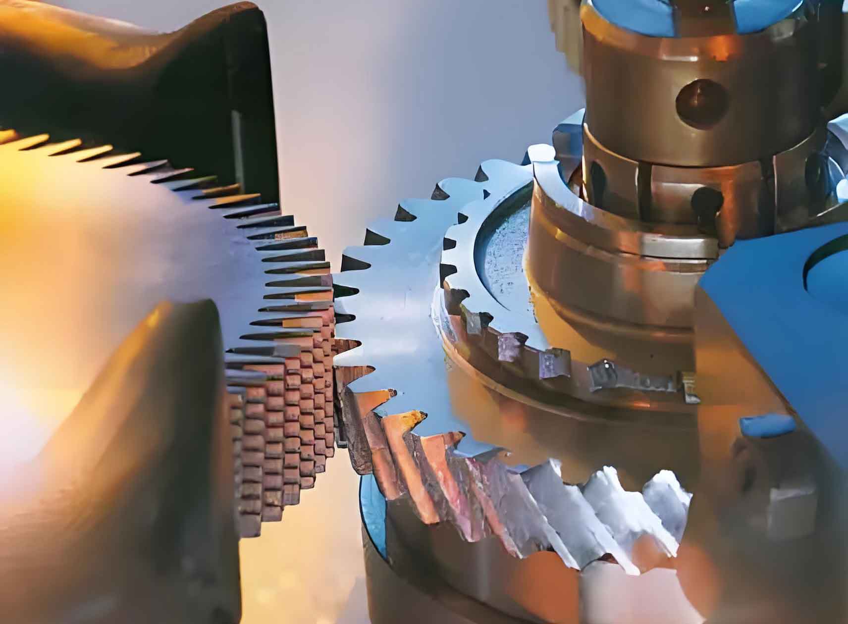
Gear transmission systems are a major contributor to noise in machine tools, particularly in lathes where high-speed operations are common. Through rigorous testing spanning over three years, I have demonstrated that within the roll-shave-hone process, strategic modification of the gear shaving tool can transform the gear tooth profile from a concave to a convex shape. This alteration, coupled with tighter tolerance controls across manufacturing stages, results in gears that meet ISO level 6 accuracy standards with a convex profile. The outcome is a stable noise reduction, bringing lathe operation below 83 dB(A), which represents a significant improvement in acoustic comfort and machine performance. This success underscores the importance of gear shaving in precision gear fabrication and noise mitigation.
The mechanism behind noise reduction via gear shaving tool modification hinges on the interaction between tooth profile geometry and meshing dynamics. In conventional roll-shave-hone processes, gears often exhibit a concave tooth profile due to the inherent kinematics of the gear shaving operation. During gear shaving, the tool and workpiece engage in a meshing action without backlash, leading to variable sliding velocities across the tooth flank. Near the pitch circle, where single-tooth contact occurs, the cutting pressure is higher, causing excessive material removal and resulting in a concave profile. This concave shape, while minimizing base pitch errors and avoiding tip-edge contact, introduces significant periodic errors during meshing. At high circumferential speeds exceeding 10 m/s, the rapid alternation of contact lines at the root and tip regions generates two impacts per cycle, leading to velocity fluctuations and a sharp increase in noise levels.
In contrast, a convex tooth profile, achieved through careful gear shaving tool correction, offers superior noise characteristics. Although minor base pitch errors may persist, the periodic error is reduced due to the more uniform meshing behavior. Contact occurs primarily in the central region of the tooth flank, where velocity changes are minimal, and the meshing alternation pattern eliminates tip-edge contact. This results in a slower rise in noise under acceleration and loading conditions. To validate this, I conducted comparative noise tests on lathes equipped with gears produced via two different processes: roll-shave-hone with convex profiles and grinding. Both sets of gears met ISO level 6 accuracy, with ground gears slightly higher in precision, but the noise measurements revealed that the convex-profile gears from the gear shaving process performed comparably, if not better, in terms of acoustic output. The table below summarizes the impact of concave versus convex tooth profiles on key noise-related parameters, highlighting the advantages of convex profiles achieved through optimized gear shaving.
| Tooth Profile | Meshing Alternation Type | Contact Region | Periodic Error | Noise Level | Manufacturing Process |
|---|---|---|---|---|---|
| Concave | Root-tip impact | Root and tip | High | High | Roll-shave |
| Convex | Central flank contact | Central flank | Low | Low | Roll-shave-hone with modified gear shaving |
The design of a concave-profile gear shaving tool to produce convex gears requires precise calculation of parameters based on the gear module and desired convexity. The goal is to reduce the cutting amount near the pitch circle by grinding a concave form into the tool’s tooth flank. This involves defining several geometric variables, as illustrated in the design schematic. Key parameters include the tool’s concave depth $$C_t$$, the concave arc width $$W_t$$, the height from the tooth tip to the concave center $$H_t$$, and the corresponding values for the guide plate used in tool grinding, such as guide plate concave depth $$C_g$$ and width $$W_g$$. These are derived from the workpiece’s convexity requirements and the kinematics of the gear shaving process.
Through experimental iterations, I have established optimal convexity values for gears operating at circumferential speeds below 10 m/s and meeting ISO level 6 accuracy. The table below lists the recommended convexity amounts for different gear modules, which guide the gear shaving tool design. These values ensure that the final gear profile is sufficiently convex to mitigate noise while maintaining precision.
| Gear Module (mm) | Recommended Convexity (μm) |
|---|---|
| 2 | 5–8 |
| 2.5 | 6–10 |
| 3 | 8–12 |
| 4 | 10–15 |
The gear shaving tool’s concave profile is characterized by a specific curve, typically an arc, whose parameters are calculated using geometric relations. For instance, the concave depth $$C_t$$ can be related to the desired gear convexity $$C_w$$ through an empirical factor $$k$$ that accounts for process dynamics: $$C_t = k \cdot C_w$$, where $$k$$ ranges from 1.2 to 1.5 based on tool wear and material properties. The concave width $$W_t$$ is determined by the contact zone during gear shaving and can be approximated as $$W_t = 2 \cdot \sqrt{R_t^2 – (R_t – C_t)^2}$$, where $$R_t$$ is the radius of the concave arc. Similarly, for the guide plate used in tool grinding, the concave values are derived from the tool design, considering the lever ratio of the grinding machine’s dressing mechanism, typically 1:40. The guide plate concave depth $$C_g$$ is calculated as $$C_g = \frac{C_t}{40}$$, and the width $$W_g$$ is proportionally scaled.
To facilitate this, I have compiled design tables for common gear modules. The table below provides specific parameters for gear shaving tools and guide plates, ensuring reproducibility in manufacturing. These parameters are critical for achieving consistent convex profiles through gear shaving.
| Parameter | Symbol | Value for Module 2.5 mm (example) | Unit |
|---|---|---|---|
| Tool concave depth | $$C_t$$ | 12 | μm |
| Tool concave width | $$W_t$$ | 1.2 | mm |
| Tool concave center height | $$H_t$$ | 4.5 | mm |
| Guide plate concave depth | $$C_g$$ | 0.3 | μm |
| Guide plate concave width | $$W_g$$ | 0.8 | mm |
| Grinding wheel diameter | $$D_s$$ | 300 | mm |
The process of grinding the gear shaving tool to achieve the desired concave profile requires meticulous attention to detail. On a gear grinding machine, such as a model with a 1:40 lever ratio for dresser adjustment, the steps involve preparing the guide plate, setting up the grinding wheel, and executing the grind. First, the guide plate’s reference surface must be cleaned and mounted flat to minimize positional errors. The dressing mechanism’s导轨 are adjusted to ensure minimal间隙 and smooth movement, with a sharp diamond cutter to accurately form the grinding wheel into a convex shape corresponding to the guide plate’s concave form. The worktable inclination is tuned to eliminate pressure angle errors, ensuring a straight tooth profile on the tool.
Key tolerances during tool grinding include a positional error limit of 0.005 mm for the concave arc center and a profile error within 0.003 mm. The concave depth parameters must adhere to the design tables, with regular verification using profile measurement instruments. The figure illustrates ideal versus不合格 tool profiles, emphasizing that the concave curve should be smooth and centered to avoid pressure angle deviations or asymmetric wear during gear shaving. The grinding process is iterative, often requiring multiple trials to achieve the optimal tool geometry for effective gear shaving.
Once the gear shaving tool is prepared, the next critical phase is test-shaving gears to validate the convex profile. The success of gear shaving in producing convex gears depends not only on tool quality but also on the precision of pre-shaving operations. For example, using a gear with module 2.5 mm and 20 teeth as a test case, I enforce strict requirements on blank preparation: the bore must be ISO grade 2 with a surface finish of Ra 0.8 μm, keyway or round bore tolerances within 0.01 mm, and face runout limited to 0.015 mm. During hobbing, a pre-shave hob with three pressure angles and large diameter is employed, with accuracy targets including tooth ring radial runout ΔFr ≤ 0.03 mm, base tangent length variation ΔW ≤ 0.02 mm, and profile error Δf ≤ 0.015 mm. The allowance for gear shaving is controlled at 0.10–0.15 mm per flank.
During gear shaving, the fixture must have radial and axial runout under 0.005 mm, with tool speed set at 200 rpm and feed rate at 0.05 mm per stroke. The resulting gear accuracy should achieve ΔFr ≤ 0.02 mm, Δf ≤ 0.01 mm with a convex profile, and helix error ΔFβ ≤ 0.008 mm. Additionally, a slight “刃带” or edge at the tooth tip is preserved to prevent tip-edge contact during meshing. The table below contrasts gears shaved with different tool concave profiles, showing how variations in tool geometry affect the final tooth form and noise performance. This underscores the importance of precise tool modification in gear shaving.
| Tool Concave Profile | Resulting Gear Profile | Pressure Angle Error | Noise Impact |
|---|---|---|---|
| Ideal concave | Convex | Minimal | Low noise |
| Concave too deep | Excess convexity | Positive deviation | Moderate noise increase |
| Concave too shallow | Near-concave | Negative deviation | High noise |
| Concave off-center | Asymmetric convexity | Variable | Unstable noise |
Post-shaving processes, such as heat treatment and honing, are equally vital for maintaining gear accuracy and noise reduction. For high-frequency hardening, the impact on tooth profile is generally minimal, though slight tip shrinkage may occur, increasing the pressure angle. Bore shrinkage is common; for small shrinkage, cold rolling is used with negligible effect on profile and helix errors, while larger shrinkage necessitates push broaching, which can exacerbate face runout and profile deviations. Thin-walled gears benefit from glow discharge ion nitriding, which avoids distortion and eliminates the need for bore correction.
Honing, performed on a dual-pressure honing machine, involves bidirectional honing at a spindle speed of 300 rpm with a feed rate of 0.02 mm per stroke. The process time and stroke count are minimized to prevent profile degradation, targeting helix error ΔFβ ≤ 0.005 mm and maintaining a convex profile. Final gear accuracy must meet ISO level 6: profile error Δf ≤ 0.01 mm (convex), base pitch deviation Δfpb ± 0.005 mm, surface finish Ra 0.4 μm, and helix error ΔFβ ≤ 0.008 mm. When measured with a master gear in double-flank testing, the variation per tooth Δfa’ should be ≤ 0.01 mm and per revolution ΔFr’ ≤ 0.02 mm.
To ensure consistency, I have compressed standard tolerances based on production data. For instance, compared to ISO 1328 standards for grade 6 gears, parameters like ΔFr can be tightened by 30%, Δf by 40%, and ΔFβ by 25%. The table below presents实测 accuracy data for critical gears in a lathe headstock, demonstrating that through controlled gear shaving and process optimization, ISO level 6 accuracy with convex profiles is achievable, leading to effective noise reduction. This table highlights the公差 compression possible in a roll-shave-hone process with focused gear shaving tool modification.
| Accuracy Parameter | ISO Grade 6 Tolerance (μm) | Compressed Tolerance in Practice (μm) | Typical Measured Value (μm) |
|---|---|---|---|
| Tooth profile error Δf | 11 | 7 | 5–8 |
| Base pitch deviation Δfpb | ±9 | ±5 | ±3–6 |
| Helix error ΔFβ | 12 | 8 | 6–9 |
| Radial runout ΔFr | 22 | 15 | 12–16 |
In conclusion, the modification of gear shaving tools to produce convex tooth profiles is a highly effective strategy for reducing gear noise in machine tools. By understanding the meshing dynamics and carefully designing tool parameters, I have successfully implemented a roll-shave-hone process that yields gears with consistent convexity and high precision. The key lies in the iterative optimization of gear shaving—from tool design and grinding to pre- and post-process controls—ensuring that each stage contributes to the final acoustic performance. Through this approach, noise levels in lathes have been stabilized below 83 dB(A), with reductions of 3–5 dB(A) achieved reliably. This underscores the critical role of gear shaving in modern gear manufacturing, not only for accuracy but also for noise mitigation, making it an indispensable technique in high-performance machine tool production. The integration of detailed tables and formulas, as presented here, provides a practical framework for engineers seeking to replicate these results, emphasizing the repeated application of gear shaving principles across the manufacturing chain.