
In modern large-scale mechanical presses, the crankshaft drive often utilizes an eccentric gear system. For eccentric spur gears, a fundamental requirement is that the axis of the eccentric bore, the gear center, and the center of the tooth (or tooth space) opposite the gear center must all lie on a single straight line. This alignment is critical for ensuring the synchronization of the press slide after assembly. For spur gears, verifying this condition is relatively straightforward, as it can be directly measured on the gear’s end face. However, in recent years, to enhance driving smoothness and load distribution, the use of herringbone gears in large press drives has become prevalent. Despite the change in gear geometry, the same fundamental alignment requirement persists for these eccentric herringbone gears. The challenge arises because the presence of a helix angle prevents a direct end-face measurement as performed on spur gears. This necessitates the development of a relative measurement method to assess the symmetry of the eccentric bore relative to the gear’s tooth structure.
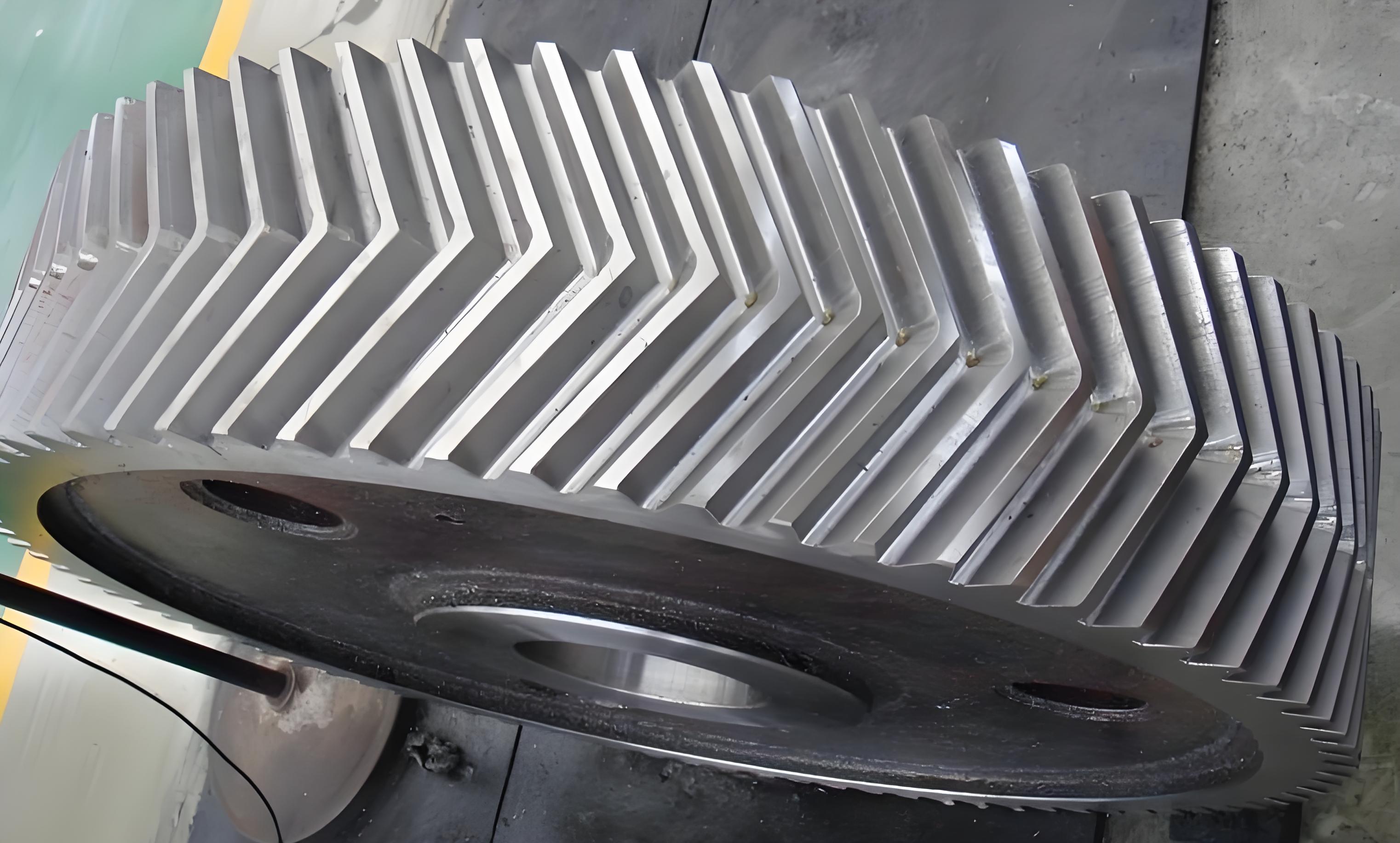
The core of the process involves measuring a rough-machined eccentric bore on a finished herringbone gear (where the teeth and the central bore are already machined). The essence is to measure the symmetry of this eccentric bore relative to the left and right flanks of the gear’s tooth space aligned with the gear center. The helical nature of the teeth means a physical reference point on the tooth flank shifts axially relative to a datum plane. Therefore, we employ a method using precision steel balls as locators. The diameter of these balls is selected based on the gear module. The balls are positioned to contact the tooth flank tangentially at the pitch circle, with the ball’s center lying precisely in the axial plane defined by the gear’s end face where the eccentricity is specified. The relative distance from the centers of the balls placed in symmetrically opposite tooth spaces to the wall of the eccentric bore is then measured. The critical insight is that for a spur gear, this measured difference would be zero for a perfectly centered bore. For a herringbone gear, due to the directional helix, a predictable, non-zero theoretical difference exists. By comparing the actual measured difference to this calculated theoretical value, we determine the machining adjustment required for the eccentric bore.
1. Theoretical Foundation and Calculation Methodology
The measurement principle hinges on precise geometric calculations to account for the helix-induced shift. The following sections detail the step-by-step procedure to determine the theoretical phase difference against which the physical measurement is compared.
1.1 Determination of Measurement (Tooth) Position
Prior to measurement, we must identify the specific tooth spaces on the left and right flanks that are symmetric about the gear’s center and lie in a direction perpendicular to the axis of eccentricity. This simplifies vector calculations. For a gear with a right-hand helix (as an example), the process is as follows:
First, calculate the angle from the eccentric axis to the perpendicular direction:
$$ A_c1 = \arccos\left(\frac{E}{R}\right) $$
where:
$E$ = Eccentricity (distance from gear center to eccentric bore center).
$R$ = Pitch circle radius.
Then, calculate the nominal number of teeth to span from the center tooth space to our measurement point:
$$ Z_m’ = Z \times \frac{A_c1}{360^\circ} $$
where:
$Z$ = Total number of teeth on the herringbone gear.
The value $Z_m’$ is then rounded to the nearest whole number to obtain the practical span count, $Z_m$. This defines the tooth spaces used for ball placement.
1.2 Angular Deviation Due to Helix-Induced Axial Shift
The helix angle $\beta$ causes the contact point of the steel ball on the tooth flank to be axially offset from the reference end-face plane. Even when we ensure the ball center is in the reference plane (by accounting for ball radius), the point of tangency circumferentially shifts. This results in a small circumferential offset $f$.
$$ f = (H – S) \cdot \tan(\beta) $$
where:
$H$ = Radius of the steel ball.
$S$ = Axial setting error or intentional offset from the end face (can be zero if ball center is set exactly at the face).
$\beta$ = Helix angle.
This circumferential offset translates to an angular deviation $A_s$ on the pitch circle:
$$ A_s = \frac{f}{2\pi R} \times 360^\circ = \frac{f \cdot 360^\circ}{2\pi R} $$
1.3 Angular Position of Ball Centers Relative to Gear Center
The central angle corresponding to the rounded span $Z_m$ is:
$$ A_c = \left( \frac{Z_m}{Z} \right) \times 360^\circ $$
For a right-hand helix herringbone gear, the left-side ball (viewed against the direction of eccentricity) will be shifted to a larger angle, and the right-side ball to a smaller angle. Thus:
$$ A_l = A_c + A_s $$
$$ A_r = A_c – A_s $$
where $A_l$ and $A_r$ are the angles from the eccentric axis line to the left and right ball centers, respectively.
1.4 Distance from Ball Centers to Eccentric Bore Center
Using the law of cosines, the distances from the gear center ($O$) to the left and right ball centers ($L$ and $R$) are both equal to $R$. The distance from the gear center to the eccentric bore center ($O’$) is $E$. The included angles are $A_l$ and $A_r$. Therefore, the distances from the ball centers to the eccentric bore center ($X_l$ and $X_r$) are:
$$ X_l = \sqrt{R^2 + E^2 – 2RE \cos(A_l)} $$
$$ X_r = \sqrt{R^2 + E^2 – 2RE \cos(A_r)} $$
1.5 Theoretical Phase Difference (Distance Difference)
The theoretical difference in distance, or phase difference $L_{theory}$, is simply:
$$ L_{theory} = X_l – X_r $$
For the described right-hand helix case, $X_l > X_r$, so $L_{theory}$ is positive. This value is the calculated benchmark for a perfectly symmetric eccentric bore in a herringbone gear.
| Variable | Symbol | Formula / Description |
|---|---|---|
| Eccentricity | $E$ | Given design parameter |
| Pitch Radius | $R$ | $m_t \cdot Z / 2$, where $m_t$ is transverse module |
| Helix Angle | $\beta$ | Given design parameter (sign matters for RH/LH) |
| Span Tooth Count | $Z_m$ | Rounded value of $Z \times \arccos(E/R) / 360^\circ$ |
| Base Angle | $A_c$ | $(Z_m / Z) \times 360^\circ$ |
| Circumferential Shift | $f$ | $(H – S) \cdot \tan(\beta)$ |
| Angular Deviation | $A_s$ | $(f \cdot 360^\circ) / (2\pi R)$ |
| Left Ball Angle | $A_l$ | $A_c + A_s$ (for RH helix) |
| Right Ball Angle | $A_r$ | $A_c – A_s$ (for RH helix) |
| Left Distance | $X_l$ | $\sqrt{R^2 + E^2 – 2RE \cos(A_l)}$ |
| Right Distance | $X_r$ | $\sqrt{R^2 + E^2 – 2RE \cos(A_r)}$ |
| Theoretical Phase Diff. | $L_{theory}$ | $X_l – X_r$ |
2. Design and Operation of the Measuring Instrument
To physically perform this relative measurement, a dedicated gauge is designed. Its function is to accurately capture the difference $L_{actual} = X_{l,actual} – X_{r,actual}$ in a stable and repeatable manner.
The gauge typically consists of a rigid base, a movable carriage or arm holding a precision ground steel ball, and a high-accuracy dial indicator or electronic probe. The ball holder is designed to allow the ball to seat securely against the chosen tooth flank while referencing the gear’s end face. The probe is positioned to contact the wall of the rough-machined eccentric bore.
2.1 Measurement Procedure:
- Gear Setup: The finished herringbone gear is placed horizontally. The eccentric direction is identified. Following the calculation in Section 1.1, one counts $Z_m$ teeth from the central tooth space (aligned with the gear center) to the left and to the right along the perpendicular direction. These are the measurement datum tooth spaces.
- Left-Side Reference Set: The gauge’s ball is placed into the left datum tooth space. The carriage is adjusted so the ball contacts the tooth flank tangentially and its axial position is set relative to the gear end face (accounting for ball radius $H$). The probe is brought into contact with the eccentric bore wall and the dial indicator is zeroed or the reading is noted. The entire left-side assembly (carriage and probe holder) is then locked in position. This establishes the reference distance $X_{l,actual}$ indirectly.
- Right-Side Measurement: Keeping the left-side assembly fixed, the ball is moved and placed into the right datum tooth space. The gauge’s right-side arm or a separate referencing arm is adjusted so the ball contacts the right flank correctly. The probe, still fixed relative to the left-side setup, now contacts the bore wall again. The new reading on the dial indicator directly represents the displacement difference, which is the actual phase difference $L_{actual}$.
- Deviation Calculation: The deviation $\Delta$ of the eccentric bore from perfect symmetry is calculated by comparing the measured and theoretical phase differences:
$$ \Delta = L_{actual} – L_{theory} $$
Interpretation of $\Delta$:
- If $\Delta = 0$, the eccentric bore is perfectly symmetric relative to the herringbone gear’s tooth structure in the measured plane.
- If $\Delta \neq 0$, an offset exists. For the final boring operation, the eccentric bore’s center must be adjusted by $\Delta/2$ in the appropriate direction perpendicular to the eccentric axis to achieve symmetry.
| Step | Action | Purpose / Outcome |
|---|---|---|
| 1 | Calculate $Z_m$, $L_{theory}$. | Establish theoretical benchmark for the specific herringbone gear. |
| 2 | Position gear, identify datum tooth spaces. | Prepare for physical measurement. |
| 3 | Set ball and probe on left side, lock fixture. | Fix the reference distance $X_{l,actual}$ in the gauge system. |
| 4 | Move ball to right side, take probe reading. | Obtain direct reading of $L_{actual}$. |
| 5 | Calculate $\Delta = L_{actual} – L_{theory}$. | Quantify bore misalignment. |
| 6 | Apply offset of $\Delta/2$ during finish boring. | Correct eccentric bore position to achieve symmetry. |
3. Error Analysis and Practical Considerations for Herringbone Gears
The accuracy of this method for eccentric herringbone gears depends on several factors. A primary advantage is that it is a relative measurement, so systematic errors in the gauge’s absolute dimensions tend to cancel out. However, several sources of potential error must be minimized:
1. Ball Diameter and Placement: The steel ball must contact the tooth flank at the pitch circle. An incorrect ball diameter or improper placement can introduce a cosine error. The ball’s axial position relative to the reference end face must be precisely controlled to match the assumption in the calculation for $f$ (where $S$ is known).
2. Gear Tooth Quality: Variations in tooth profile (involute error) or lead (helix angle error) of the finished herringbone gear will affect the precise tangential contact point of the ball. This is mitigated by using high-quality, ground herringbone gears typical in such press applications.
3. Calculation Accuracy: The formulas assume perfect geometry. Using high-precision computation (sufficient decimal places for angles, etc.) is essential. The effect of rounding $Z_m$ to an integer must be accepted; it is usually negligible for gears with a reasonable number of teeth.
4. Gauge Rigidity and Repeatability: The fixture must be rigid to prevent deflection during ball placement and probing. The locking mechanisms must be secure to prevent shift between the left-side setup and right-side measurement.
5. Bore Surface Condition: The rough-bored eccentric surface should be sufficiently smooth and round to allow consistent probe contact without catching on deep tool marks.
| Error Source | Effect on $L_{actual}$ | Mitigation Strategy |
|---|---|---|
| Incorrect ball diameter | Shifts contact point, altering $f$ and $A_s$. | Use calibrated balls; select size based on transverse module/pitch. |
| Axial positioning error ($S$) | Directly changes $f$, impacting $A_s$ calculation. | Use precision height gauge or datum surface for axial setting. |
| Tooth profile/lead error | Changes local contact geometry, introducing noise. | Ensure high-quality gear manufacturing; take multiple readings. |
| Probe contact inconsistency | Adds random variation to the reading. | Use a pointed probe tip; ensure stable, perpendicular contact. |
| Gauge/fixture deflection | Causes non-repeatable shift between measurements. | Design fixture with high stiffness; minimize overhang. |
4. Comparative Advantage Over Alternative Methods
This relative measurement method offers distinct advantages for herringbone gears, especially when compared to attempting to use coordinate measuring machines (CMMs) or custom spur-gear methods.
Simplicity and Cost: The dedicated fixture is mechanically simple and robust, suitable for a workshop environment. It does not require sophisticated programming or a climate-controlled metrology lab.
Inherent Compensation: The method inherently accounts for the helix angle through the calculated $L_{theory}$. There is no need to physically trace the helical flank or compute complex 3D offsets from a CAD model during measurement.
Direct Feedback for Machining: The output $\Delta$ gives a direct, linear value for the machine tool offset ($\Delta/2$) required in the final boring operation. This is immediately actionable for the machinist.
Suitability for Large Gears: The fixture can be designed to accommodate very large herringbone gears used in heavy presses, which might be impractical or extremely expensive to measure on a CMM.
In conclusion, the symmetry measurement of eccentric bores in herringbone gears presents a unique geometric challenge due to the helix angle. The method described, based on relative measurement using steel ball locators and a precisely calculated theoretical phase difference, provides an elegant and practical solution. It translates a complex 3D alignment problem into a manageable 1D relative measurement. By rigorously calculating the expected distance difference $L_{theory}$ for a perfect herringbone gear and comparing it to the physically measured $L_{actual}$, one can accurately determine the required corrective offset for the final machining of the eccentric bore. This ensures that the critical functional requirement—alignment of the eccentric bore axis with the gear center and the symmetric tooth space—is met, guaranteeing the subsequent synchronous operation of the mechanical press. The reliability of this method has been proven in the manufacturing of large-scale power press drives utilizing eccentric herringbone gears.