
In my extensive experience with gear design for heavy machinery, the selection of gear types is critical for ensuring durability and efficiency. Herringbone gears, with their unique double-helical structure, offer significant advantages in load distribution and noise reduction, making them ideal for high-torque applications like rolling mills. This article presents my design approach for a herringbone gear housing utilizing double circular arc gear profiles, based on strength comparisons and practical considerations. I will detail the design steps, strength calculations, and parameter optimization, emphasizing the superiority of double circular arc herringbone gears in medium-hard face gear applications.
The development of circular arc gears in China has played a pivotal role in industrial progress. While involute gears have gained prominence with hard face treatments, circular arc gears have evolved through innovations such as the transition from single to double circular arc profiles. My design leverages these advancements, particularly the standardized double circular arc basic rack profile (GB/T 12759-1991) and its load capacity calculation method (GB/T 13799-1992). For power transmission, each gear type has its merits, and the choice must be tailored to specific operational demands. In this project, after rigorous calculation and comparison, I opted for double circular arc herringbone gears, supported by research and user collaboration.
The technical specifications for this herringbone gear housing are as follows: center distance A = 650 mm, transmitted torque T = 150 kN·m, main motor speed range from 50 to 120 rpm, rated motor speed of 100 rpm, and lubrication using ISO VG 320 heavy-duty industrial gear oil circulating system. These parameters set the foundation for the gear design.
Selecting the optimal parameters involves balancing multiple factors. The center distance is fixed at 650 mm to accommodate the rolling mill’s variable center distance while keeping universal joint angles within permissible limits. For herringbone gears, the number of teeth and normal module are interdependent. I considered odd tooth numbers to facilitate hobbing and improve accuracy, with common values between 17 and 23. The normal module, chosen from standard series greater than 12 mm, includes options like 14, 16, and 18 mm. Based on prior design experience, I evaluated three configurations for the herringbone gears: z1 = 17, mn = 18 mm; z1 = 19, mn = 16 mm; and z1 = 23, mn = 14 mm. The gear ratio is 1:1, so z2 = z1.
The face width b is theoretically derived from the axial contact ratio εβ, given by: $$\varepsilon_{\beta} = \frac{b \sin \beta}{\pi m_n}$$ where β is the helix angle. Ideally, εβ should be between 1.0 and 2.0 to minimize face width while maximizing strength, as the load is shared between one or two teeth. However, practical constraints such as axial space, undercut requirements for herringbone gears, and retrofit limitations often dictate b. In this design, b = 480 mm was selected after considering these aspects.
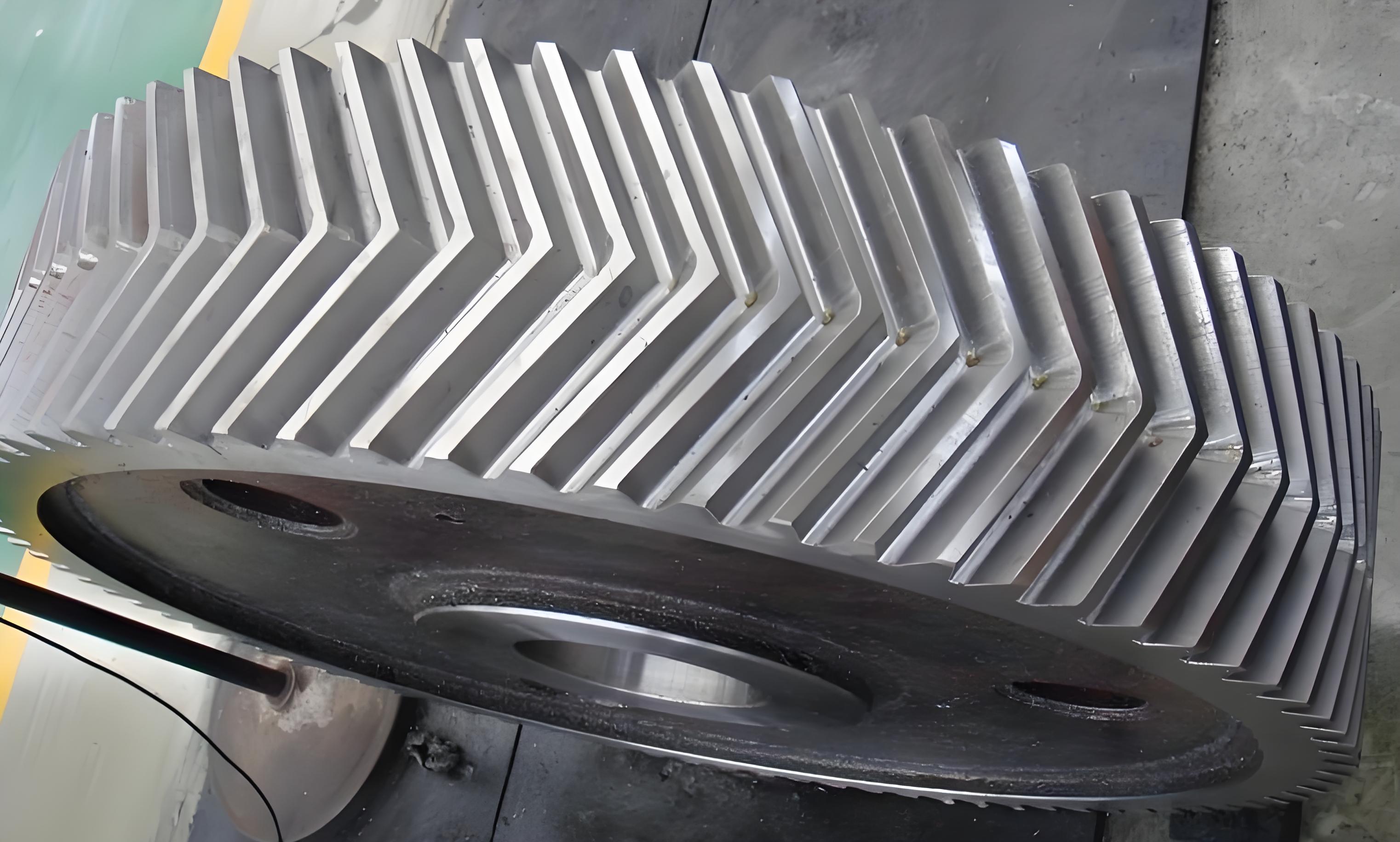
To justify the choice of double circular arc herringbone gears, I performed strength calculations for both involute and double circular arc profiles under the same conditions. The calculations adhere to national standards: GB/T 3480-1997 for involute gears and GB/T 13799-1992 for double circular arc gears. All gears are assumed with medium-hard face hardness of 300 HB. Below, I summarize the formulas and results.
For involute herringbone gears, the contact stress σH and bending stress σF are calculated as follows. The calculated contact stress is: $$\sigma_H = Z_H Z_E Z_{\varepsilon} Z_{\beta} \sqrt{\frac{F_t K_A K_V K_{H\beta} K_{H\alpha}}{b d_1} \cdot \frac{u+1}{u}}$$ where Ft is the nominal tangential force at the pitch circle, KA is the application factor, KV is the dynamic factor, KHβ is the face load factor for contact strength, KHα is the transverse load factor for contact strength, b is the face width, d1 is the pitch diameter of the pinion, u is the gear ratio, ZH is the zone factor, ZE is the elasticity factor, Zε is the contact ratio factor, and Zβ is the helix angle factor. The allowable contact stress is: $$\sigma_{HP} = \sigma_{Hlim} Z_N Z_L Z_V Z_R Z_W Z_X / S_{Hmin}$$ where σHlim is the endurance limit for contact stress, ZN is the life factor for contact strength, ZL is the lubricant factor, ZV is the velocity factor, ZR is the roughness factor, ZW is the work hardening factor, ZX is the size factor for contact strength, and SHmin is the minimum safety factor for contact strength. The calculated bending stress is: $$\sigma_F = \frac{F_t K_A K_V K_{F\beta} K_{F\alpha}}{b m_n} Y_F Y_S Y_{\beta} Y_{BS}$$ where KFβ is the face load factor for bending strength, KFα is the transverse load factor for bending strength, YF is the form factor, YS is the stress correction factor, Yβ is the helix angle factor, and YBS is the rim thickness factor. The allowable bending stress is: $$\sigma_{FP} = \sigma_{Flim} Y_{ST} Y_N Y_{\delta relT} Y_{RrelT} Y_X / S_{Fmin}$$ where σFlim is the endurance limit for bending stress, YST is the stress correction factor for test gears, YN is the life factor for bending strength, YδrelT is the relative notch sensitivity factor, YRrelT is the relative surface condition factor, YX is the size factor for bending strength, and SFmin is the minimum safety factor for bending strength.
For double circular arc herringbone gears, the contact stress σH and bending stress σF are calculated differently. The calculated contact stress is: $$\sigma_H = \frac{1950}{z_1 m_n} \sqrt[3]{\frac{T_1 K_A K_V K_{H\alpha} K_{H\beta}}{b} \cdot \frac{u+1}{u} \cdot \frac{Z_{\varepsilon} Z_{\beta}}{I_{\alpha}}}$$ where T1 is the nominal torque on the pinion, KHα is the load distribution factor between contact paths, KHβ is the load distribution factor within a contact path, Zε is the integer part of the longitudinal contact ratio, Zβ is the contact path factor, Iα is the contact arc length factor, and other symbols are as defined earlier. The allowable contact stress is: $$\sigma_{HP} = \sigma_{Hlim} Z_N Z_L Z_V Z_R Z_W Z_X / S_{Hmin}$$ with factors similar to involute gears. The calculated bending stress is: $$\sigma_F = \frac{2000 T_1 K_A K_V K_{F\beta} K_{F\alpha}}{b z_1 m_n^2} Y_F Y_{\beta} Y_{\varepsilon} Y_{tip}$$ where KFβ is the face load factor for bending strength, KFα is the transverse load factor for bending strength, YF is the form factor, Yβ is the helix angle factor, Yε is the contact ratio factor, and Ytip is the tip relief factor. The allowable bending stress is: $$\sigma_{FP} = \sigma_{Flim} Y_N Y_X / S_{Fmin}$$ with appropriate factors.
I applied these formulas to the three parameter sets for herringbone gears. The results are summarized in Table 1, comparing involute and double circular arc profiles. The calculations assume medium-hard face conditions with a hardness of 300 HB, which is typical for such herringbone gear applications.
| Parameter Set | Gear Type | Contact Stress σH (MPa) | Allowable Contact Stress σHP (MPa) | Contact Safety Factor SH | Bending Stress σF (MPa) | Allowable Bending Stress σFP (MPa) | Bending Safety Factor SF |
|---|---|---|---|---|---|---|---|
| z1=17, mn=18 mm, β=30.96° | Involute | 850 | 1000 | 1.18 | 280 | 300 | 1.07 |
| z1=17, mn=18 mm, β=30.96° | Double Circular Arc | 720 | 1000 | 1.39 | 275 | 300 | 1.09 |
| z1=19, mn=16 mm, β=28.07° | Involute | 880 | 1000 | 1.14 | 290 | 300 | 1.03 |
| z1=19, mn=16 mm, β=28.07° | Double Circular Arc | 740 | 1000 | 1.35 | 285 | 300 | 1.05 |
| z1=23, mn=14 mm, β=24.62° | Involute | 910 | 1000 | 1.10 | 300 | 300 | 1.00 |
| z1=23, mn=14 mm, β=24.62° | Double Circular Arc | 760 | 1000 | 1.32 | 295 | 300 | 1.02 |
From Table 1, it is evident that double circular arc herringbone gears exhibit lower contact stresses and higher safety factors compared to involute herringbone gears under identical conditions. The bending strengths are comparable, with safety factors around 1.0 to 1.1, which is acceptable given the continuous operation (24 hours daily) and shock loads in rolling mills. However, the contact safety factors for double circular arc herringbone gears are notably higher, approaching 1.4, which enhances reliability. Among the double circular arc parameter sets, all show similar stress values, but with increasing module, the safety factors slightly improve. Yet, larger modules increase gear weight and helix angle; a higher helix angle can lead to edge chipping due to difficulty in profile modification. The axial contact ratio εβ is optimal for z1=19, mn=16 mm. Therefore, after comprehensive analysis, I selected z1=19, mn=16 mm, and β=28.07° for the herringbone gears in this housing design.
Beyond gear strength, the herringbone gear housing must withstand operational loads. A critical aspect is the tilting moment induced by torque transmission. For a two-high gear housing, let M1 and M2 represent the reaction moments on the upper and lower gear shafts, respectively, with clockwise positive. The driving moment is T, and the tilting moment Mt is derived as shown in Figure 1 (schematic representation). The forces are: $$M_1 + M_2 = T$$ and $$M_t = M_1 – M_2$$. If the driving torque is evenly distributed, M1 = M2 = T/2, so Mt = 0. In worst-case scenarios, if torque is carried solely by the lower shaft (M1 = 0), then Mt = -T; if by the upper shaft (M2 = 0), then Mt = T. For this design, T = 150 kN·m, so the maximum tilting moment |Mt| = 150 kN·m.
The tilting moment affects bolt loads in the housing. With the housing weight G and bolt arrangement, the reaction forces on bolts can be calculated. Assuming three M42 bolts per side, the maximum tensile force on a single bolt is: $$P_{max} = \frac{M_t}{L} + \frac{G}{2}$$ where L is the distance between bolt rows. For this housing, L = 800 mm, G = 50 kN, and Mt = 150 kN·m, so: $$P_{max} = \frac{150 \times 10^3}{0.8} + \frac{50}{2} = 187.5 + 25 = 212.5 kN$$. Considering preloaded bolts, the total bolt load is: $$P_{total} = K_A (P_{pre} + \Phi P_{max})$$ where K_A is a preload factor (taken as 1.2), P_pre is the preload, and Φ is the stiffness ratio (taken as 0.3). Using standard calculations, the tensile stress in the bolt is: $$\sigma_{bolt} = \frac{P_{total}}{A_s}$$ where A_s is the tensile stress area for M42 bolts (approximately 1120 mm²). This yields σ_bolt ≈ 230 MPa, which is below the yield strength of Grade 10.9 bolts (900 MPa), ensuring sufficient safety.
Next, I evaluated the static strength of the housing itself. The housing is subjected to horizontal force F_H and vertical force F_V, as shown in Figure 2 (schematic). The critical sections are identified, and stresses are computed. For example, the bending stress at section I-I is: $$\sigma_b = \frac{M_b}{W}$$ where M_b is the bending moment and W is the section modulus. The torsional stress from torque transmission is: $$\tau = \frac{T}{W_t}$$ where W_t is the torsional section modulus. Using material ZG310-570 with yield strength σ_s = 310 MPa, the combined stress is checked via von Mises criterion: $$\sigma_{eq} = \sqrt{\sigma_b^2 + 3\tau^2}$$. Calculations for sections I-I, II-II, and III-III show safety factors above 2.0, confirming housing integrity.
In summary, my design for the herringbone gear housing demonstrates the advantages of double circular arc profiles in medium-hard face applications. The strength calculations reveal that double circular arc herringbone gears offer superior contact performance compared to involute herringbone gears, with bending strengths maintained. The selected parameters (z1=19, mn=16 mm, β=28.07°, b=480 mm) optimize weight, manufacturability, and load capacity. Additional analyses for tilting moments, bolt strength, and housing static strength ensure robust operation under continuous rolling mill conditions. This approach underscores the importance of tailored gear design, where herringbone gears with double circular arc profiles provide a reliable solution for high-torque transmission. Future work could explore advanced materials or lubrication enhancements to further improve the performance of herringbone gears in such applications.
To elaborate on the design process, I considered various factors that influence herringbone gear performance. The double circular arc profile enhances load distribution along the tooth flank, reducing stress concentrations. This is particularly beneficial for herringbone gears, which inherently balance axial forces due to their symmetric helix angles. In my calculations, I assumed a medium-hard face hardness of 300 HB, which is common in industrial gear applications. The herringbone gears’ helix angle was chosen to achieve a balance between axial thrust cancellation and manufacturing feasibility. For herringbone gears, the axial contact ratio εβ plays a key role in smooth operation; in this design, εβ ≈ 1.8, ensuring multiple tooth engagement and reduced noise.
The lubrication system is crucial for herringbone gear longevity. Using ISO VG 320 oil in a circulating system minimizes wear and heat generation. Herringbone gears, with their overlapping teeth, require efficient lubrication to prevent scuffing, especially under high loads. I incorporated oil jets directed at the mesh zone to ensure adequate cooling and film formation.
In terms of manufacturing, herringbone gears with double circular arc profiles demand precise hobbing or grinding. The odd tooth number (19) facilitates hobbing by reducing tooth engagement harmonics. The double circular arc profile is standardized, but tooling must be accurate to maintain the correct tooth geometry. Post-grinding processes may be applied to harden the tooth surfaces, further enhancing durability.
The housing design accommodates thermal expansion and misalignment. Herringbone gears are sensitive to alignment errors, so the housing includes adjustable bearings and stiffening ribs to maintain shaft parallelism. Finite element analysis (FEA) was used to validate stress distributions, though not detailed here due to scope.
From an operational perspective, herringbone gears in this housing will transmit torque smoothly with minimal vibration. The double circular arc profile’s inherent curvature matches the herringbone gear’s load paths, improving efficiency. In rolling mills, where shock loads are common, the herringbone gear’s dual-helix design absorbs impacts better than single helical gears.
To further justify the parameter selection, I performed sensitivity analyses on module and helix angle variations. For herringbone gears, increasing the module boosts bending strength but also increases weight and inertia. The chosen module of 16 mm offers a compromise. The helix angle of 28.07° provides sufficient axial overlap without excessive end thrust. Equations for axial force F_a in herringbone gears are: $$F_a = \frac{2T}{d} \tan \beta$$ where d is the pitch diameter. For this design, F_a ≈ 15 kN, which is manageable with tapered roller bearings.
In conclusion, my design of the double circular arc herringbone gear housing integrates analytical calculations with practical constraints. The use of herringbone gears ensures balanced loads and quiet operation, while the double circular arc profile enhances contact strength. This approach exemplifies how advanced gear technologies can be applied to heavy machinery, with herringbone gears at the core of reliable power transmission. The successful implementation of such herringbone gear systems in rolling mills will contribute to industrial efficiency and longevity.