
In the modern automotive industry, spiral bevel gears serve as critical components in differential systems and drive axles, enabling efficient power transmission between non-parallel shafts. Their complex geometry, characterized by curved teeth and varying pressure angles, demands high-precision manufacturing to ensure durability, noise reduction, and operational efficiency. With the rapid growth of the automotive sector, the annual demand for spiral bevel gears has surged to millions of sets globally, driving the need for advanced, cost-effective machining solutions. Traditionally, spiral bevel gears are produced using either the generating method (e.g., Gleason or Klingelnberg systems) or the form milling method. While generating offers high accuracy, form milling excels in efficiency, especially for gears with large pitch angles exceeding 70°, making it ideal for mass production in automotive applications. However, conventional form milling machines, often reliant on wet cutting with oil-based coolants, face significant drawbacks: environmental pollution, health hazards from oil mist, and high operational costs due to coolant usage and maintenance. In response, our research team embarked on developing a next-generation CNC form milling machine capable of dry cutting, incorporating structural innovations and digital controls to enhance precision, efficiency, and sustainability. This article details the development, design innovations, and practical applications of our YK2180R CNC spiral bevel gear form milling machine, emphasizing its role in advancing spiral bevel gear manufacturing.
The evolution of spiral bevel gear machining has been marked by a shift toward dry cutting, driven by ecological and economic factors. Dry cutting eliminates coolant usage, reducing waste and improving workplace safety, but it imposes stringent requirements on machine tools: high dynamic stiffness to mitigate vibrations from intermittent cutting, elevated spindle speeds for efficient chip removal and heat dissipation, direct-drive servo systems for rapid axis movements, and optimized chip evacuation designs. Internationally, companies like Gleason and Klingelnberg have introduced high-speed dry-cutting machines, such as the Phoenix II series, which feature air-based chip removal systems. However, these machines are prohibitively expensive for many manufacturers, creating a gap in the market for affordable, high-performance alternatives. Our development of the YK2180R aims to bridge this gap by integrating novel mechanical designs with CNC technology, enabling stable dry cutting at a fraction of the cost. This machine not only addresses the limitations of wet-cutting models like the Y2280 or imported Gleason 606#/608# machines but also enhances processing capabilities for spiral bevel gears, supporting the automotive industry’s push toward greener manufacturing.
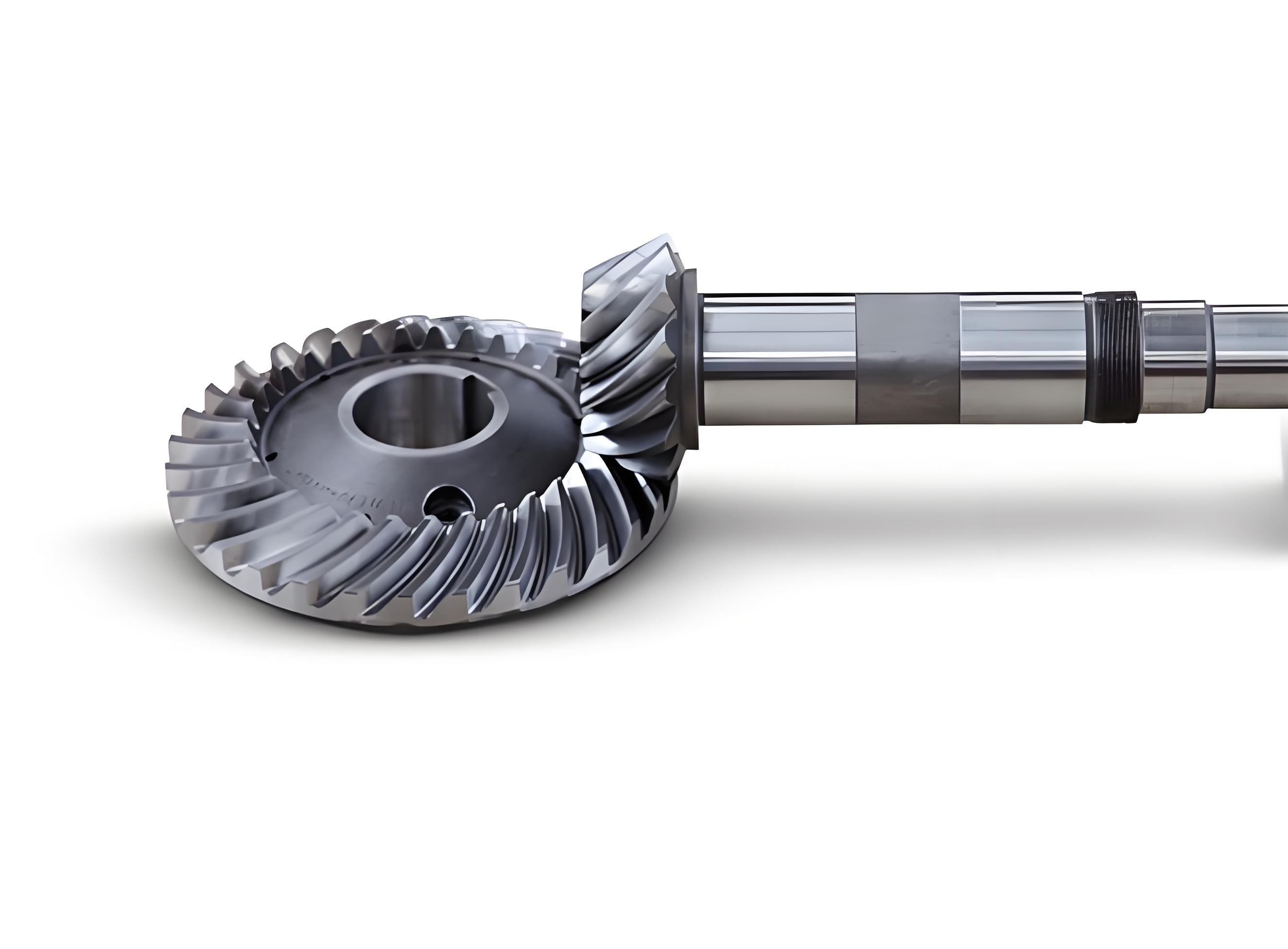
To understand the design innovations, it is essential to first grasp the geometric and kinematic principles of spiral bevel gears. Spiral bevel gears are characterized by their tooth profiles, which are typically generated via mathematical models based on conjugate action. The tooth surface can be described using parametric equations involving parameters such as spiral angle $\beta$, pitch cone angle $\delta$, and module $m$. For form milling, the cutter path is defined to approximate the gear tooth shape, with adjustments for tool positioning. Key parameters in setup include radial cutter distance $H$, vertical cutter distance $V$, and workpiece tilt angle. In traditional machines, these are adjusted mechanically, but CNC systems allow for digital control, improving accuracy and flexibility. The cutting forces during form milling vary with depth, impacting tool life and surface quality. Our machine incorporates an “constant cutting force” feed mechanism, derived from force modeling. The tangential cutting force $F_T$ can be expressed as a function of feed depth $d$ and material properties:
$$F_T = K \cdot d^n \cdot f(\text{material, tool geometry})$$
where $K$ is a constant and $n$ is an exponent typically between 0.8 and 1.2 for spiral bevel gears. By modulating feed rate to maintain $F_T$ constant, we reduce tool wear and enhance efficiency. This is implemented in the YK2260X CNC system, which computes real-time adjustments based on sensor inputs. Below, Table 1 summarizes the comparative advantages of form milling versus generating for spiral bevel gears, highlighting why form milling is preferred for high-volume production of spiral bevel gears in automotive contexts.
| Aspect | Form Milling | Generating (Rolling) |
|---|---|---|
| Efficiency | High (fast material removal) | Moderate (slower due to complex motion) |
| Accuracy | Grade 8-9 (suitable for roughing/pre-finishing) | Grade 5-6 (high precision for finishing) |
| Machine Complexity | Simpler structure, lower cost | Complex kinematics, higher cost |
| Suitability for Large Pitch Angles | Excellent (>70°) | Limited |
| Dry Cutting Feasibility | Enhanced with high-speed spindles | Challenging due to heat buildup |
The YK2180R CNC form milling machine introduces several groundbreaking innovations that address the core challenges of dry cutting for spiral bevel gears. First, the machine replaces the conventional vertical slide with an eccentric drum mechanism for adjusting vertical cutter distance. This design eliminates the need for a bulky column and slide, significantly improving structural rigidity and reducing manufacturing costs. The relationship between drum rotation angle $\phi$ and vertical distance $V$ is given by:
$$\phi = \arcsin\left(\frac{V – B}{E}\right)$$
where $E$ is the eccentric distance of the cutter spindle relative to the drum axis, and $B$ is the fixed distance between the drum axis and workpiece axis. The corresponding horizontal axis displacement $X$ is calculated as:
$$X = H – E \cos \phi – A \cos \delta_f$$
Here, $H$ is the nominal radial distance, $A$ is the distance from the gear blank apex to the workpiece spindle center, and $\delta_f$ is the root angle of the spiral bevel gear. This drum-based adjustment enhances stability during high-speed dry cutting, as it minimizes vibration-prone components. Second, the machine employs a direct-drive servo system with a high-precision double-lead worm gear for indexing, replacing traditional indexing plates and lock mechanisms. This allows flexible adjustment for different tooth counts without physical changeovers, crucial for small-batch production of spiral bevel gears. The worm gear provides self-locking, ensuring positional accuracy without additional clamping, which often causes centering errors in older models. The indexing accuracy achieves within 5 arcseconds, contributing to consistent tooth spacing for spiral bevel gears.
Third, the bed structure is optimized using finite element analysis (FEA) to enhance dynamic stiffness. Unlike machines with linear guides, the YK2180R incorporates integrally cast rectangular guides (150 mm × 60 mm cross-section) hardened to HRC 50-55 and ground to a surface roughness of 1.6 μm. The sliding surfaces are lined with polymer materials to dampen vibrations, essential for dry cutting where chatter can compromise surface finish. Fourth, the machine enables dry cutting through a variable-frequency motor driving the cutter spindle at speeds ranging from 45 to 500 rpm, allowing cutting velocities up to 300 m/min when using coated high-speed steel or carbide tools. An automated chip removal system with magnetic conveyors and air nozzles expels hot chips rapidly, preventing heat accumulation and protecting critical components. This system evacuates approximately 80% of generated heat, mirroring advanced designs like the Phoenix II but at lower cost. Table 2 outlines the key specifications of the YK2180R, emphasizing its capabilities for processing spiral bevel gears.
| Parameter | YK2180R Specification |
|---|---|
| Max. Gear Diameter | 800 mm |
| Spindle Speed Range | 45-500 rpm (infinitely variable) |
| Cutting Method | Dry or Wet (optional) |
| Positioning Accuracy | ±0.005 mm |
| Indexing Accuracy | ±5 arcseconds |
| Drive System | Servo motors with worm gear for indexing |
| Chip Removal | Automated magnetic conveyor + air blast |
| Control System | YK2260X CNC with constant-force algorithms |
The application results of the YK2180R demonstrate its superiority in manufacturing spiral bevel gears. In a case study involving a 153-tooth driven spiral bevel gear for automotive differentials, the machine achieved a cutting time of 20 seconds per tooth, completing the entire gear in 14 minutes—twice as fast as the Y2280 wet-cutting machine. The gear parameters and machining settings are listed in Tables 3 and 4, respectively. The rough-cut accuracy reached Grade 8 according to ISO standards, with pitch errors controlled within 0.05 mm, sufficient for subsequent finishing processes like broaching or grinding. Notably, for spiral bevel gears requiring post-heat treatment grinding, the YK2180R eliminates the need for semi-finishing before hardening, reducing process steps and costs. The dry-cutting capability also lowers tool consumption by up to 30% compared to wet cutting, as tools experience less thermal shock. When integrated into production lines with high-end machines like the Gleason Phoenix 600, the YK2180R enables a “four-cut method” for spiral bevel gears, where it performs roughing before the Phoenix 600 finishes, boosting overall line productivity by 80% and cutting tool costs by 60%.
| Parameter | Pinion | Gear (Driven) |
|---|---|---|
| Number of Teeth | 6 | 37 |
| Module (mm) | 11.732 | |
| Face Width (mm) | 67.547 | 62 |
| Pitch Cone Angle (°) | 11.311 | 78.497 |
| Root Cone Angle (°) | 10.878 | 74.934 |
| Spiral Angle (°) | 45 | 34.446 |
| Addendum (mm) | 12.956 | 1.601 |
| Whole Depth (mm) | 16.791 | |
| Adjustment Parameter | Calculated Value |
|---|---|
| Radial Cutter Distance (mm) | 162.3350 |
| Angular Cutter Position (°) | 48.3605 |
| Horizontal Workpiece Position (mm) | -2.2224 |
| Workpiece Tilt Angle (°) | 75.3413 |
The economic and environmental benefits of the YK2180R are substantial. By enabling dry cutting for spiral bevel gears, it reduces coolant consumption by 100%, eliminating associated disposal costs and health risks. The machine’s energy efficiency is enhanced through the constant-force feed system, which optimizes power usage based on real-time cutting conditions. Moreover, its construction cost is approximately 60% of comparable imported dry-cutting machines, making it accessible to small and medium-sized enterprises. To quantify performance, we conducted tests measuring instantaneous tangential cutting force $F_T$ versus feed time $t$ under constant-force mode, as shown in Figure 6 of the original context. The data confirmed that $F_T$ remained stable within ±10% of the target value, ensuring consistent material removal rates and extended tool life for spiral bevel gear production. The machine’s robustness has led to over 60 units sold domestically, with users reporting reduced maintenance intervals and higher throughput for spiral bevel gears.
In conclusion, the development of the YK2180R CNC form milling machine represents a significant advancement in the manufacturing of spiral bevel gears. Its design innovations—including the eccentric drum for vertical adjustment, servo-driven worm gear indexing, FEA-optimized bed, and integrated dry-cutting systems—collectively address the challenges of high efficiency, precision, and sustainability. The machine achieves cutting efficiencies double that of conventional wet-cutting models, with accuracies suitable for pre-finishing spiral bevel gears, and it operates without coolants, aligning with global trends toward green manufacturing. Future work will focus on enhancing the CNC algorithms for adaptive control and expanding the machine’s versatility to include other gear types. As the demand for spiral bevel gears continues to grow in automotive and aerospace sectors, technologies like the YK2180R will play a pivotal role in driving productivity and reducing environmental impact, solidifying their place in modern manufacturing landscapes.
The mathematical modeling behind the constant-force feed system warrants further elaboration. For spiral bevel gears, the cutting force dynamics can be described using differential equations that account for tool engagement geometry. The instantaneous cutting force $F_T$ is proportional to the uncut chip area $A_c$, which varies with feed depth $d$ and tooth shape. For a form-milled spiral bevel gear, $A_c$ can be approximated as:
$$A_c = w \cdot d \cdot \sin(\theta)$$
where $w$ is the chip width (dependent on gear face width) and $\theta$ is the effective engagement angle. To maintain $F_T = F_{\text{target}}$, the feed rate $v_f$ is adjusted dynamically:
$$v_f = \frac{F_{\text{target}}}{K’ \cdot A_c}$$
with $K’$ being a material-specific constant. This feedback loop is implemented in the YK2260X CNC, using sensors to monitor motor torque and adjust servo outputs. Additionally, the chip evacuation efficiency is critical for dry cutting of spiral bevel gears. The air nozzle system generates a pressure differential $\Delta P$ to propel chips, modeled as:
$$\Delta P = \frac{\rho v^2}{2} \cdot C_d$$
where $\rho$ is air density, $v$ is nozzle velocity, and $C_d$ is a discharge coefficient. Optimizing $\Delta P$ ensures that over 90% of chips are removed within seconds, preventing re-cutting and heat retention. These engineering refinements underscore the machine’s capability to handle the rigorous demands of spiral bevel gear production.
In summary, the YK2180R exemplifies how innovative mechanical design and digital control can revolutionize the processing of spiral bevel gears. By prioritizing dry cutting, high speed, and rigidity, it offers a cost-effective solution that meets the evolving needs of the automotive industry. As spiral bevel gears become more prevalent in electric vehicles and advanced drivetrains, machines like the YK2180R will be indispensable for achieving the precision and efficiency required for future mobility solutions.