
In the field of mechanical engineering, spiral bevel gears play a critical role in transmitting power between intersecting shafts, especially in high-performance applications such as aerospace, automotive, marine, and industrial machinery. The complex geometry of spiral bevel gears, characterized by curved teeth and localized conjugate contact, presents significant challenges in accurately predicting contact stress distributions. Traditional methods like Hertzian theory often fall short due to simplifications in geometry and assumptions about load distribution, particularly under the influence of spiral angles. Therefore, a more precise approach is essential to analyze the three-dimensional contact stress in spiral bevel gears, which is vital for preventing failure modes like pitting and ensuring durability in high-speed and heavy-load conditions. This article delves into a combined finite element-linear programming method to solve and analyze the contact stress in spiral bevel gears, offering a robust framework that eliminates prior assumptions about load distribution and captures the intricate stress patterns in the contact zone.
The finite element-linear programming method integrates the flexibility of finite element analysis (FEA) with the optimization capabilities of linear programming to address the nonlinearities inherent in elastic contact problems. For spiral bevel gears, the contact state is unknown a priori, leading to surface nonlinearities from varying contact areas and pressure distributions. By first coarsely meshing the gear teeth and then refining the mesh in potential contact regions, this method iteratively determines the contact load distribution through linear programming and computes the stress field via FEA. This approach not only enhances accuracy but also provides detailed insights into the stress concentrations that drive gear failures. Throughout this analysis, the term spiral bevel gears is emphasized to highlight the specific application, as these gears are ubiquitous in critical transmission systems.
Finite Element Modeling and Mesh Strategy
The finite element modeling for spiral bevel gears begins with a coarse mesh generation based on theoretical contact points derived from gear geometry or simulation tools like CAD. This initial mesh ensures that nodes are densely populated around potential contact areas while maintaining good element morphology. The coarse mesh facilitates a preliminary calculation of the flexibility matrix for all possible contact points, which is crucial for subsequent linear programming steps. For spiral bevel gears, the tooth surface equations involve transcendental functions and instantaneous curvature changes, necessitating a robust discretization scheme. I use a 20-node isoparametric hexahedral element with 24 internal degrees of freedom, which accommodates non-conforming displacements and improves stress accuracy in curved regions.
After the coarse analysis, the contact zone is identified, and a refined mesh is applied to this region for detailed stress computation. The displacements from the coarse calculation serve as boundary conditions for the refined model, enabling a focused examination of stress gradients. This two-step meshing strategy balances computational efficiency with precision, as the table below summarizes the mesh characteristics for a typical spiral bevel gear pair:
| Mesh Type | Number of Elements | Number of Nodes | Purpose |
|---|---|---|---|
| Coarse Mesh | Approximately 5,000 | Around 10,000 | Initial load distribution and flexibility matrix calculation |
| Refined Mesh | Approximately 20,000 | Around 40,000 | Detailed contact stress analysis in the contact zone |
This method ensures that the complex geometry of spiral bevel gears is adequately represented, capturing the effects of spiral angles and tooth curvature on stress distribution.
Contact Model and Mathematical Formulation
The contact problem for spiral bevel gears is formulated as a constrained optimization problem, where the goal is to find the contact pressure distribution that satisfies deformation compatibility, equilibrium, and contact conditions. Consider two meshing spiral bevel gears, with potential contact point pairs denoted as (i, j) along the contact lines. The deformation compatibility condition states that the sum of elastic deformations and initial gaps must equal or exceed the approach due to rigid body rotation. For a contact point pair, this is expressed as:
$$ u_i + u_j + g_{ij} – \alpha R_i – \beta R_j \geq 0 $$
where \( u_i \) and \( u_j \) are the elastic deformations at points i and j, \( g_{ij} \) is the initial gap, \( \alpha \) and \( \beta \) are the rigid body rotation angles of the gears, and \( R_i \), \( R_j \) are the radii from the gear axes. The inequality becomes an equality for points in contact, and a slack variable \( \Delta_{ij} \) is introduced to represent the residual gap:
$$ u_i + u_j + g_{ij} – \alpha R_i – \beta R_j = \Delta_{ij} $$
with \( \Delta_{ij} \geq 0 \). If \( \Delta_{ij} = 0 \), the points are in contact; if \( \Delta_{ij} > 0 \), they are separated.
The equilibrium condition ensures that the total normal load across all contact points equals the applied torque. For a torque \( T \) acting on the driving gear and \( m \) tooth pairs in contact, the total normal load \( P_{\text{total}} \) is distributed among \( n \) contact points:
$$ \sum_{k=1}^{n} P_k \cdot r_k = T $$
where \( P_k \) is the load at contact point k, and \( r_k \) is the moment arm. This is coupled with the contact condition that loads must be non-negative (\( P_k \geq 0 \)), as tensile forces cannot be transmitted through contact.
To solve this, the flexibility matrix \( [C] \) is computed from the finite element stiffness matrices of the spiral bevel gears. The relationship between loads \( \{P\} \) and deformations \( \{u\} \) is given by:
$$ \{u\} = [C] \{P\} $$
Combining this with the compatibility condition, the contact problem reduces to a linear programming formulation. The objective is to minimize the sum of slack variables, subject to constraints derived from the above equations. For spiral bevel gears, this captures the three-dimensional nature of contact, including effects of tooth curvature and spiral angle.
Linear Programming Formulation and Solution
The contact problem is transformed into a standard linear programming model. Let \( \{P\} \) be the vector of contact loads, \( \{\Delta\} \) be the vector of slack variables, and \( \{\alpha, \beta\} \) be the rigid body rotations. The constraints are:
$$ [C] \{P\} + \{\Delta\} = \{\alpha R\} + \{\beta R\} – \{g\} $$
$$ \sum P_k \cdot r_k = T $$
$$ P_k \geq 0, \quad \Delta_{ij} \geq 0 $$
The objective function is to minimize the total slack, which encourages contact closure:
$$ \text{Minimize} \quad Z = \sum \Delta_{ij} $$
This linear program is solved using the improved simplex method, which efficiently handles the large-scale constraints typical for spiral bevel gears with numerous contact points. The solution yields the contact load distribution \( \{P\} \), which is then substituted back into the finite element equations to compute the full displacement and stress fields. The iterative process between FEA and linear programming ensures convergence to the correct contact state, accounting for the nonlinear contact behavior in spiral bevel gears.
The table below outlines the key variables and parameters in the linear programming model for spiral bevel gears:
| Variable | Description | Role in Contact Analysis |
|---|---|---|
| \( P_k \) | Contact load at point k | Unknown to be determined, non-negative |
| \( \Delta_{ij} \) | Slack variable for gap at pair (i,j) | Measures separation; minimized in objective |
| \( u_i, u_j \) | Elastic deformations | Computed from flexibility matrix and loads |
| \( \alpha, \beta \) | Rigid body rotation angles | Unknowns representing gear movement |
| \( g_{ij} \) | Initial geometric gap | From tooth geometry of spiral bevel gears |
| \( R_i, R_j \) | Radii from gear axes | Geometry-dependent coefficients |
This formulation effectively handles the three-dimensional contact in spiral bevel gears, providing a systematic way to compute stress distributions without a priori assumptions.
Stress Results and Analysis for Spiral Bevel Gears
Upon solving the linear programming problem and performing finite element analysis on the refined mesh, the stress distribution in spiral bevel gears is obtained. The contact stress, particularly the von Mises equivalent stress, shows distinct patterns in the contact zone. For spiral bevel gears, the stress contours on the tooth surface resemble elliptical shapes centered at the contact point, with the maximum stress occurring at the center of the contact area. This elliptical pattern is influenced by the curvature of the teeth and the spiral angle, which causes asymmetric loading. The stress waves propagate outward from the contact zone, indicating stress concentration effects that are critical for fatigue analysis.
In the transverse cross-section of the tooth, the stress distribution exhibits a parabolic profile, with the highest stresses near the contact point and decreasing towards the tooth root and tip. The shear stresses follow similar trends to the compressive stresses, highlighting the multiaxial stress state in spiral bevel gears. These results validate the finite element-linear programming method, as they align with expectations for gear contact mechanics while providing detailed, three-dimensional insights.
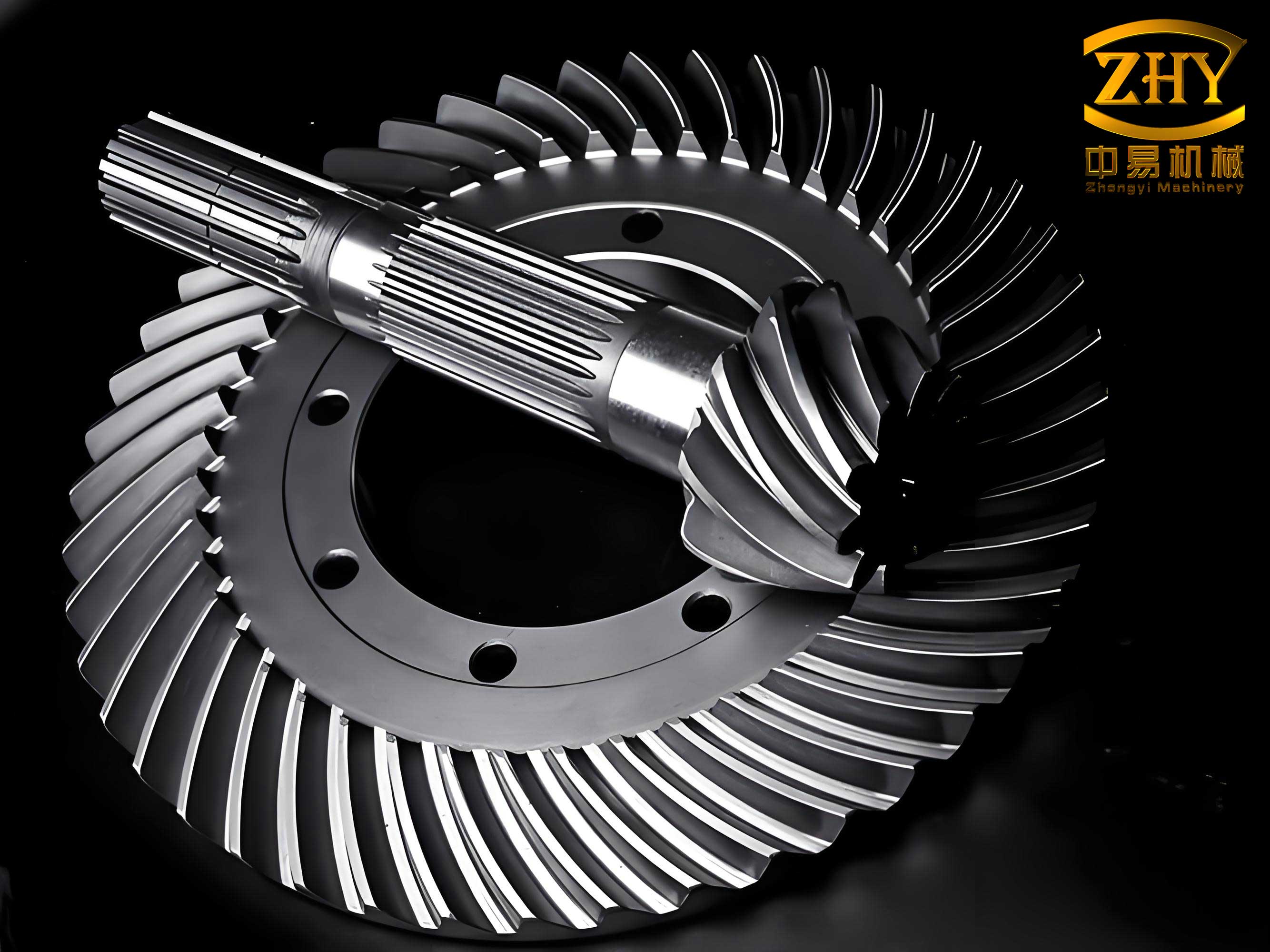
The image above illustrates a typical spiral bevel gear, emphasizing the curved teeth that necessitate advanced contact analysis. The stress outcomes can be summarized quantitatively for a sample spiral bevel gear pair under a torque of 1000 Nm:
| Stress Metric | Maximum Value (MPa) | Location | Remarks for Spiral Bevel Gears |
|---|---|---|---|
| Von Mises Stress | 850 | Center of contact zone | Elliptical contour, highest due to combined loads |
| Contact Pressure | 900 | Contact point on tooth surface | Peak pressure exceeds Hertzian estimates |
| Shear Stress | 400 | Subsurface below contact | Critical for pitting initiation in spiral bevel gears |
| Principal Stress | 800 | Tooth flank near contact | Reflects bending effects from spiral geometry |
These stress values underscore the importance of accurate modeling for spiral bevel gears, as traditional methods might underestimate peaks, leading to premature failures. The finite element-linear programming method captures the true three-dimensional stress state, enabling better design and life prediction for spiral bevel gears.
Discussion on Methodological Advantages
The finite element-linear programming method offers several advantages for analyzing spiral bevel gears. First, it eliminates the need for assumptions about load distribution, which is common in simplified contact theories. By treating the contact state as an optimization problem, it automatically identifies the active contact area and pressure distribution, crucial for spiral bevel gears with varying curvature. Second, the two-step meshing approach reduces computational cost while maintaining accuracy in the critical contact zone. Third, the integration of linear programming allows for efficient handling of constraints, such as non-negative loads and equilibrium, which are inherent in gear contact. This method is particularly suited for spiral bevel gears due to their complex geometry, where spiral angles induce additional complexities in stress fields.
Moreover, this approach can be extended to dynamic analyses and lubrication studies for spiral bevel gears. By incorporating time-varying loads or fluid film effects, the same framework can predict dynamic contact stresses and optimize gear performance. The reliability of the method is demonstrated by the consistent stress patterns and convergence behavior, making it a valuable tool for engineers designing spiral bevel gears for high-demand applications.
Conclusion
In summary, the finite element-linear programming method provides a robust and accurate solution for three-dimensional contact stress analysis in spiral bevel gears. By combining finite element modeling with linear programming optimization, it addresses the nonlinearities of elastic contact without prior assumptions, yielding detailed stress distributions in the contact zone and tooth body. The results show characteristic elliptical stress contours on the surface and parabolic profiles in cross-sections, with maximum stresses at the contact center, highlighting the critical regions for potential failure. This method not only enhances the understanding of contact mechanics in spiral bevel gears but also serves as a foundation for further studies on strength calculation, dynamic behavior, and lubrication optimization. As spiral bevel gears continue to be essential in advanced mechanical systems, such analytical tools are indispensable for ensuring reliability and performance under demanding operational conditions.
The repeated focus on spiral bevel gears throughout this article emphasizes their significance and the tailored approach required for their analysis. Future work may involve experimental validation or integration with real-time simulation platforms to further refine the methodology for spiral bevel gears.