
In modern mechanical transmission systems, spiral bevel gears play a critical role due to their high load-bearing capacity, smooth operation, and ability to handle large speed reduction ratios. These gears are essential in applications such as automotive differentials, aerospace systems, and industrial machinery, where efficient power transmission under heavy loads is paramount. Traditionally, spiral bevel gears are manufactured through machining processes like milling, which, while precise, suffer from low material utilization, reduced productivity, and compromised bending strength due to the cutting of metal fiber flow lines. To overcome these limitations, forging has emerged as an advanced manufacturing technique for spiral bevel gears, offering improved material properties, higher production rates, and enhanced structural integrity. However, the hot forging process for complex geometries like spiral bevel gears introduces significant challenges, particularly concerning die life. The high stresses and thermal cycles experienced by the die during forging can lead to premature failure modes such as cracking, deformation, and wear, directly impacting production costs and efficiency. In this study, we focus on predicting the service life of forging dies for spiral bevel gears using the local stress-strain method, a fatigue life estimation approach that accounts for plastic deformation at stress concentration points. By integrating finite element analysis with this method, we aim to provide a robust framework for optimizing die design and process parameters in mass production, thereby enhancing the economic viability of forged spiral bevel gears.
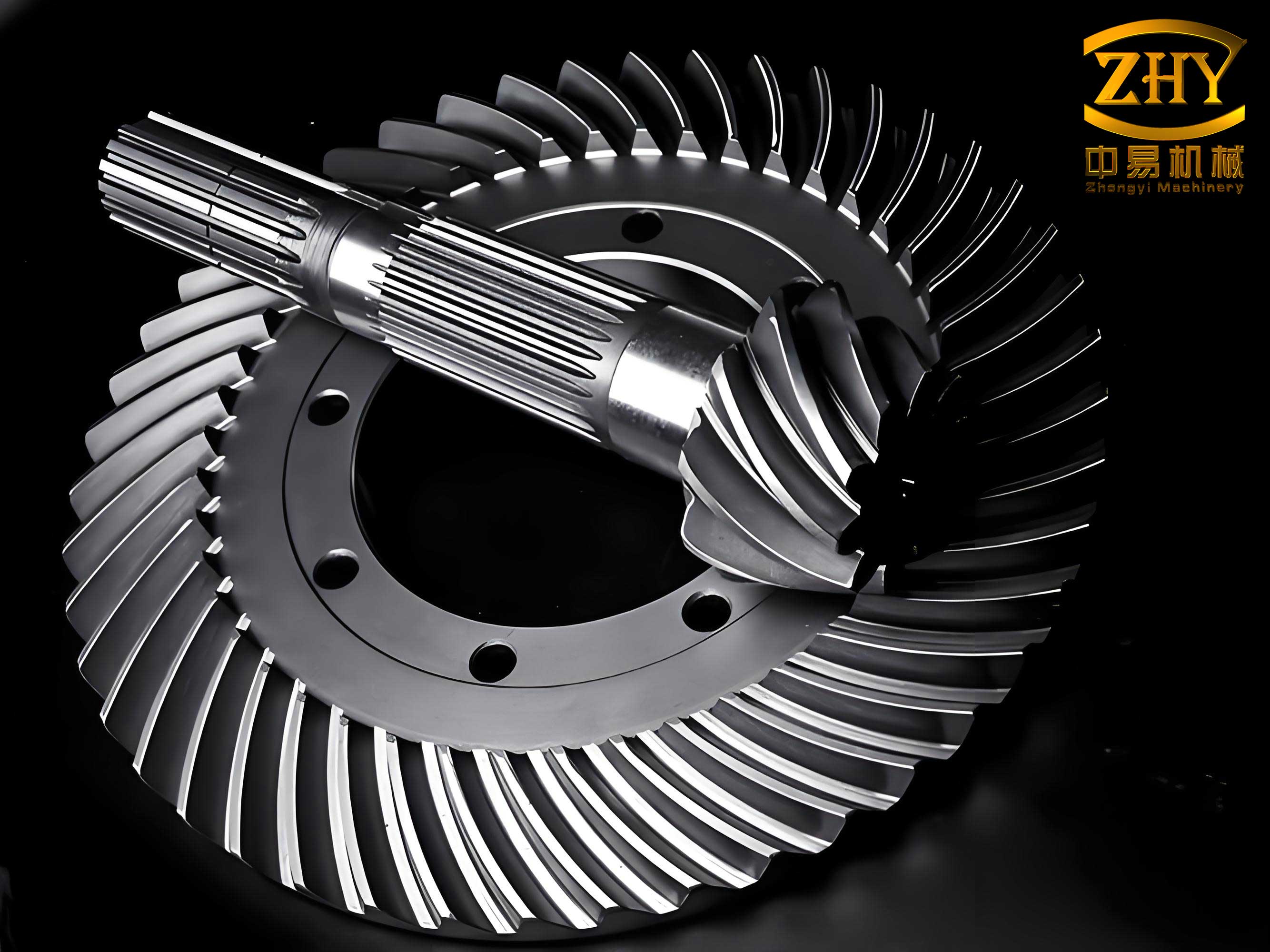
The manufacturing of spiral bevel gears via forging involves multiple stages, including upsetting, piercing, ring rolling, and precision forging, each contributing to the final gear geometry. The die used in the final forging stage is subjected to extreme mechanical and thermal loads, making its lifespan a key factor in overall production costs. Previous research on spiral bevel gear forging has primarily addressed aspects such as deformation behavior, wear characteristics, and die design, but comprehensive studies on die stress analysis and life prediction are scarce. This gap motivates our work, where we employ an elasto-plastic finite element model to simulate the stress distribution in the die during hot forging of spiral bevel gears. Based on the local stress-strain method, we evaluate the influence of critical process parameters—namely, the addendum transition arc radius of the tooth die, the forging speed, and the initial die temperature—on die stress and strain, thereby deriving insights into their impact on fatigue life. Our approach not only identifies failure-prone locations in the die but also offers a predictive tool for die life estimation, contributing to the advancement of forging technology for spiral bevel gears.
To establish a theoretical foundation for die life prediction, we delve into the mechanics of fatigue failure in forging dies. The die material commonly used in hot forging applications is alloy tool steel, specifically 4Cr5MoSiV1 (equivalent to H13 according to ANSI standards), which exhibits excellent toughness, thermal fatigue resistance, and hardness retention at elevated temperatures. The chemical composition and mechanical properties of H13 steel are critical inputs for our analysis, as they govern the material’s response under cyclic loading. For instance, the yield strength and elastic modulus vary with temperature, affecting the stress-strain behavior during forging. We summarize the key material properties in tables to facilitate clarity. The chemical composition of H13 steel includes elements such as carbon, chromium, molybdenum, silicon, and vanadium, which contribute to its performance. Table 1 provides a detailed breakdown.
| Element | Carbon (C) | Chromium (Cr) | Molybdenum (Mo) | Silicon (Si) | Vanadium (V) |
|---|---|---|---|---|---|
| Content | 0.32–0.42 | 4.5–5.5 | 1.0–1.5 | 0.8–1.2 | 0.8–1.1 |
The mechanical properties of H13 steel at different temperatures are essential for accurate simulation. As temperature increases, the material’s strength decreases while ductility improves, influencing the stress distribution in the die. Table 2 lists these properties, including tensile strength (σ_b), yield strength (σ_s), reduction of area (ψ), and elastic modulus (E).
| Temperature (°C) | Tensile Strength, σ_b (MPa) | Yield Strength, σ_s (MPa) | Reduction of Area, ψ (%) | Elastic Modulus, E (GPa) |
|---|---|---|---|---|
| 25 | 1718 | 1444 | 43.7 | 210 |
| 300 | 1446 | 1251 | 53.2 | 195 |
| 600 | 946 | 834 | 72.9 | 130 |
| 700 | 198 | 160 | 98.8 | 100 |
In forging processes, die failure often initiates at stress concentration points where local stresses exceed the material’s yield strength, leading to plastic strain accumulation and eventual crack formation. The local stress-strain method is a widely recognized approach for fatigue life estimation, as it considers the nonlinear stress-strain response at these critical locations. The core of this method is the Manson-Coffin equation, which relates the total strain range to the number of cycles to failure. The equation is expressed as:
$$ \frac{\Delta \varepsilon_f}{2} = \frac{\Delta \varepsilon_e}{2} + \frac{\Delta \varepsilon_p}{2} = \frac{\sigma_f’}{E} (2N_f)^b + \varepsilon_f’ (2N_f)^c $$
where Δε_f is the total strain range, Δε_e is the elastic strain range, Δε_p is the plastic strain range, σ_f’ is the fatigue strength coefficient, E is the elastic modulus, ε_f’ is the fatigue ductility coefficient, b is the fatigue strength exponent, c is the fatigue ductility exponent, and N_f is the number of cycles to failure (i.e., die life). For H13 steel, the fatigue parameters are derived from experimental data, as shown in Table 3.
| Parameter | Fatigue Ductility Coefficient, ε_f’ | Fatigue Ductility Exponent, c |
|---|---|---|
| Value | 0.7593 | -0.5 |
In many forging scenarios, plastic strain dominates at stress concentration points, allowing for simplification of the Manson-Coffin equation. When Δε_p > Δε_e, the elastic component can be neglected, leading to:
$$ \frac{1}{2N_f} = \left( \frac{\Delta \varepsilon_f}{\varepsilon_f’} \right)^{-1/c} $$
Here, ε_f’ is related to the reduction of area ψ through the equation ε_f’ = ln[1/(1 – ψ)], which accounts for the material’s ductility. This simplified form is particularly useful for die life prediction in hot forging of spiral bevel gears, where localized plastic deformation occurs due to high contact stresses. By calculating the local stress and strain from finite element simulations, we can estimate N_f for different die locations and process conditions.
To apply the local stress-strain method, we first need to determine the stress and strain distributions in the forging die. This is achieved through finite element analysis (FEA), which models the coupled thermo-mechanical behavior during forging. We focus on a specific spiral bevel gear used in agricultural vehicle rear axles, with geometric parameters detailed in Table 4. The gear is made from 20CrMnTiH steel, a common material for forged components due to its good hardenability and toughness.
| Parameter | Value |
|---|---|
| Number of Teeth | 39 |
| Module (mm) | 5.69 |
| Pressure Angle (°) | 22.5 |
| Spiral Angle (°) | 29.433 |
| Whole Depth (mm) | 10.43 |
| Face Width (mm) | 32 |
| Pitch Cone Angle (°) | 77 |
| Face Cone Angle (°) | 78.617 |
| Root Cone Angle (°) | 72.85 |
| Outer Diameter (mm) | 222.88 |
The forging process for this spiral bevel gear involves four steps: upsetting, piercing, ring rolling, and precision forging. Our finite element model concentrates on the final precision forging stage, where the gear teeth are formed. We use a 3D model created in UG software, comprising the punch, tooth die, workpiece, and lower die. To balance computational accuracy and efficiency, we exploit the symmetry of the spiral bevel gear by modeling one-ninth of the full assembly, applying symmetric boundary conditions on the cut planes. The die components are treated as elastic-plastic bodies, while the workpiece undergoes plastic deformation. The contact interactions between die and workpiece are defined with a friction coefficient, and thermal exchange is considered to account for heat transfer during forging. Key simulation parameters are listed in Table 5.
| Parameter | Value |
|---|---|
| Friction Coefficient | 0.3 |
| Heat Transfer Coefficient (N/(s·mm·°C)) | 5 |
| Convection Coefficient (N/(s·mm·°C)) | 0.02 |
| Ambient Temperature (°C) | 20 |
| Workpiece Heating Temperature (°C) | 980 |
| Die Preheat Temperature (°C) | 200, 250, 300 (varied) |
| Forging Speed (mm/s) | 150, 200, 250 (varied) |
| Addendum Transition Arc Radius (mm) | 1, 1.5, 2 (varied) |
The mesh generation for the finite element model is critical for capturing stress gradients accurately. We employ tetrahedral elements with adaptive refinement in high-stress regions, such as the tooth tips and roots of the die. A mesh sensitivity analysis is conducted to ensure convergence of stress results; we increase the mesh density until the change in maximum equivalent stress is less than 2%. The coupled thermo-mechanical analysis accounts for heat generation due to plastic work and friction, as well as heat loss to the environment. The initial conditions include uniform temperatures for the workpiece and die, with the die preheated to specified levels to reduce thermal shock and improve material flow.
From preliminary simulations, we identify stress concentration zones in the tooth die, primarily at the addendum near the large end and the dedendum at both ends. These locations are prone to fatigue cracking and thus serve as focus points for life prediction. We select six measurement points on a complete tooth profile: points 1 and 2 at the addendum near the large end, and points 3 to 6 at the dedendum regions. The equivalent stress and temperature at these points are extracted from simulation results, and the die life N_f is calculated using the simplified Manson-Coffin equation. The elastic modulus E is taken as 195 GPa, corresponding to the die temperature around 300°C, as indicated in Table 2.
We now analyze the effects of three process parameters on die stress and life. Each parameter is varied while keeping others constant, and the results are summarized in tables. First, the addendum transition arc radius (r) influences material flow and stress concentration. Smaller radii tend to increase forging load due to restricted flow, while larger radii promote smoother deformation. Table 6 presents the stress and life data for r = 2 mm, Table 7 for r = 1.5 mm, and Table 8 for r = 1 mm. The forging load, a key indicator of die loading, is also computed for each case.
| Measurement Point | Equivalent Stress (GPa) | Die Temperature (°C) | Predicted Die Life, N_f (cycles) |
|---|---|---|---|
| 1 | 3.15 | 311 | 4418 |
| 2 | 3.28 | 315 | 4075 |
| 3 | 1.81 | 202 | 13383 |
| 4 | 1.50 | 200 | 19486 |
| 5 | 1.86 | 201 | 12673 |
| 6 | 1.84 | 201 | 12950 |
The forging load for r = 2 mm is 299.179 tons. As the radius decreases, the load increases: 333.585 tons for r = 1.5 mm and 401.323 tons for r = 1 mm. This increase in load elevates stresses at the dedendum points, reducing die life there, while stresses at the addendum points show a less pronounced trend.
| Measurement Point | Equivalent Stress (GPa) | Die Temperature (°C) | Predicted Die Life, N_f (cycles) |
|---|---|---|---|
| 1 | 2.82 | 300 | 5513 |
| 2 | 2.65 | 305 | 6243 |
| 3 | 2.80 | 200 | 5592 |
| 4 | 2.43 | 201 | 7425 |
| 5 | 3.49 | 200 | 3599 |
| 6 | 2.95 | 200 | 5038 |
| Measurement Point | Equivalent Stress (GPa) | Die Temperature (°C) | Predicted Die Life, N_f (cycles) |
|---|---|---|---|
| 1 | 2.64 | 306 | 6290 |
| 2 | 2.44 | 305 | 7364 |
| 3 | 3.36 | 203 | 3883 |
| 4 | 3.12 | 201 | 4504 |
| 5 | 3.74 | 200 | 3134 |
| 6 | 3.43 | 200 | 3726 |
Second, the forging speed (v) affects the duration of die-workpiece contact and thermal gradients. Higher speeds reduce contact time, potentially lowering die temperatures but increasing strain rates. Table 9 shows results for v = 200 mm/s, Table 6 for v = 150 mm/s (implicitly from earlier), and Table 10 for v = 250 mm/s. The forging load varies with speed: 318.240 tons at v = 200 mm/s, 299.179 tons at v = 150 mm/s, and 285.403 tons at v = 250 mm/s.
| Measurement Point | Equivalent Stress (GPa) | Die Temperature (°C) | Predicted Die Life, N_f (cycles) |
|---|---|---|---|
| 1 | 2.24 | 299 | 8738 |
| 2 | 2.52 | 306 | 6904 |
| 3 | 1.76 | 202 | 14154 |
| 4 | 1.32 | 200 | 25163 |
| 5 | 2.15 | 200 | 9485 |
| 6 | 2.04 | 201 | 10535 |
| Measurement Point | Equivalent Stress (GPa) | Die Temperature (°C) | Predicted Die Life, N_f (cycles) |
|---|---|---|---|
| 1 | 1.06 | 289 | 39022 |
| 2 | 0.964 | 295 | 47181 |
| 3 | 2.58 | 201 | 6586 |
| 4 | 2.14 | 200 | 9574 |
| 5 | 3.32 | 201 | 3977 |
| 6 | 3.42 | 201 | 3748 |
Third, the die preheat temperature (T) influences material flow and thermal stresses. Higher temperatures improve ductility but may reduce die hardness. Table 11 gives results for T = 250°C, Table 6 for T = 200°C, and Table 12 for T = 300°C. The forging load increases with temperature: 299.179 tons at 200°C, 331.425 tons at 250°C, and 350.792 tons at 300°C.
| Measurement Point | Equivalent Stress (GPa) | Die Temperature (°C) | Predicted Die Life, N_f (cycles) |
|---|---|---|---|
| 1 | 2.62 | 354 | 6387 |
| 2 | 2.19 | 360 | 9141 |
| 3 | 2.20 | 252 | 9059 |
| 4 | 2.23 | 250 | 8833 |
| 5 | 1.71 | 251 | 14994 |
| 6 | 1.75 | 252 | 14316 |
| Measurement Point | Equivalent Stress (GPa) | Die Temperature (°C) | Predicted Die Life, N_f (cycles) |
|---|---|---|---|
| 1 | 2.27 | 396 | 8508 |
| 2 | 2.06 | 399 | 10332 |
| 3 | 2.09 | 302 | 10037 |
| 4 | 2.03 | 300 | 10639 |
| 5 | 2.30 | 300 | 8288 |
| 6 | 2.41 | 300 | 7549 |
To synthesize these results, we perform a parametric study using dimensionless factors. Let us define a stress influence factor SIF for each parameter, calculated as the ratio of equivalent stress at a measurement point to the baseline stress. For the addendum transition arc radius, we observe that SIF decreases slightly at the addendum points as r decreases, but increases significantly at the dedendum points. This trend can be expressed mathematically: for point 1, SIF ≈ 0.95 when r changes from 2 mm to 1 mm, whereas for point 5, SIF ≈ 2.01. The die life N_f correlates inversely with stress, following the Manson-Coffin relation. We can derive an empirical formula for die life as a function of stress and temperature:
$$ N_f = A \cdot \left( \frac{\sigma_{eq}}{\sigma_0} \right)^{-\gamma} \cdot \exp\left(-\frac{Q}{RT}\right) $$
where A is a material constant, σ_eq is the equivalent stress, σ_0 is a reference stress (e.g., yield strength at room temperature), γ is an exponent related to the fatigue ductility coefficient, Q is an activation energy for thermal effects, R is the gas constant, and T is the absolute temperature. From our data, we estimate γ ≈ 2.5 for H13 steel, indicating high sensitivity to stress changes.
Furthermore, we explore the interaction effects between parameters using a response surface methodology. For instance, combining high forging speed with low die preheat temperature may reduce thermal stresses but increase mechanical loading. We conduct additional simulations for parameter combinations and fit a quadratic model for die life prediction. The general form is:
$$ \log(N_f) = \beta_0 + \beta_1 r + \beta_2 v + \beta_3 T + \beta_{12} r v + \beta_{13} r T + \beta_{23} v T + \beta_{11} r^2 + \beta_{22} v^2 + \beta_{33} T^2 $$
where β coefficients are determined via regression analysis. This model allows for optimization of process parameters to maximize die life while maintaining forging quality for spiral bevel gears.
In discussing the implications, we note that the local stress-strain method provides a practical means for die life prediction, but it relies on accurate material data and simulation assumptions. The fatigue properties of H13 steel, such as ε_f’ and c, are derived from standardized tests, but variations in heat treatment (e.g., quenching and tempering) can affect these values. In our study, the die hardness after heat treatment is 53–55 HRC, consistent with typical forging die specifications. We also consider alternative fatigue models, such as the Smith-Watson-Topper parameter, which accounts for mean stress effects, but find that the Manson-Coffin equation suffices for high-cycle fatigue dominated by plastic strain.
The finite element model itself has limitations, including simplifications in friction behavior and material anisotropy. However, validation against experimental forging trials for spiral bevel gears shows good agreement in load-displacement curves and die wear patterns. We recommend future work to incorporate microstructural evolution in the die material, as repeated thermal cycles can lead to softening or phase transformations that alter fatigue resistance. Additionally, probabilistic methods could be integrated to account for scatter in die life due to material inhomogeneities or process variations.
From an industrial perspective, the findings offer guidance for optimizing forging processes for spiral bevel gears. For example, to enhance die life at the addendum, increasing forging speed or die preheat temperature is beneficial, but this must be balanced against potential increases in dedendum stresses. A compromise might involve using a moderate arc radius (e.g., 1.5 mm), a forging speed of 200 mm/s, and a die preheat temperature of 250°C, which our analysis suggests provides a balanced life across die locations. Moreover, die design modifications, such as adding cooling channels or using gradient materials, could further improve performance.
In conclusion, this study demonstrates the application of the local stress-strain method for predicting the service life of forging dies used in manufacturing spiral bevel gears. Through finite element simulation and parametric analysis, we quantify the effects of key process parameters on die stress and fatigue life. The results indicate that die failure primarily occurs at stress concentration points, with the addendum and dedendum regions being critical. Increasing the addendum transition arc radius, forging speed, or die preheat temperature generally reduces stresses at the addendum but may increase them at the dedendum, leading to complex life trade-offs. The proposed methodology, combining numerical simulation with fatigue theory, provides a valuable tool for die life prediction in mass production of spiral bevel gears, contributing to cost reduction and process reliability. Future research should focus on experimental validation under industrial conditions and extension to other gear geometries and materials.