
In precision transmission systems, such as those used in robotic wrist joints and aerospace mechanisms, the demand for compact, high-ratio reducers has led to the development of nutation drives. These drives leverage gyroscopic motion principles to achieve significant speed reduction in a limited space. Central to their performance are the double circular-arc spiral bevel gears, which transmit motion between the oscillating and output components. The contact characteristics of these spiral bevel gears—encompassing tooth contact patterns, stress distribution, contact ratio, and load sharing—are critical indicators of transmission efficiency, durability, and noise generation. Understanding these characteristics through loaded tooth contact analysis (LTCA) is essential for optimizing design and ensuring reliability. In this study, we employ the finite element method (FEM) to comprehensively analyze the contact behavior of double circular-arc spiral bevel gears in a nutation drive configuration. We derive the tooth surface geometry, construct a detailed three-dimensional model, simulate meshing under load, and investigate the influences of operational load and assembly inaccuracies. The insights gained aim to guide the design and application of these specialized spiral bevel gears in high-performance nutation transmissions.
Geometric Modeling of Double Circular-Arc Spiral Bevel Gears
The foundation of any contact analysis lies in an accurate geometric model. For double circular-arc spiral bevel gears, the tooth surface is generated based on the concept of a crown gear (or generating gear) that is in simultaneous mesh with both the external and internal spiral bevel gears. The crown gear’s tooth profile in its normal section is defined by a double circular-arc curve, as standardized in certain gear specifications. This profile consists of convex and concave arc segments connected by transition curves.
We establish a series of coordinate systems to facilitate the derivation. Let \( S_n(x_n, y_n, z_n) \) be the coordinate system attached to the double circular-arc tooth profile in its normal plane, with the \( x_n \)-axis along the profile symmetry line and the \( y_n \)-axis along the pitch line. The position vector of any point on the \( i \)-th arc segment of the profile can be expressed as:
$$ \mathbf{r}_{ni} = \begin{pmatrix} x_{ni} \\ y_{ni} \\ z_{ni} \end{pmatrix} = \begin{pmatrix} r_i \sin \alpha_i + E_i \\ r_i \cos \alpha_i + F_i \\ 0 \end{pmatrix}, \quad \text{for } i = 1, 2, \ldots, 8 $$
Here, \( r_i \) and \( \alpha_i \) are the radius and angular parameter of the arc, respectively, while \( (E_i, F_i) \) denote the coordinates of the arc center. The index \( i \) covers all segments: convex arcs, concave arcs, and fillet curves. To generate the three-dimensional tooth surface of the crown gear, this profile is swept along a predetermined tooth trace on the crown gear’s pitch plane. We employ an oblique spherical curve (a curve with constant spiral angle \( \beta \)) as this tooth trace. Its parametric equations in the crown gear coordinate system \( S_c \) are:
$$ x’_p = x_p + [\pm (\rho_j – l_j)] \sin(\theta – \Delta\theta_j + \beta) $$
$$ y’_p = y_p – [\pm (\rho_j – l_j)] \cos(\theta – \Delta\theta_j + \beta) $$
In these equations, \( \rho_j \) is the radius of curvature, \( l_j \) is a center offset, \( \theta \) is a parameter, and \( \Delta\theta_j \) is an angular offset. The sign convention depends on whether the left or right flank of the spiral bevel gear is being generated. The complete tooth surface of the crown gear, \( \mathbf{r}_c \), is obtained by combining the profile equation with the trace equation through coordinate transformations.
The tooth surfaces of the external and internal spiral bevel gears are then derived as envelopes of the crown gear surface during the simulated meshing motion of the nutation drive. The kinematic relationship between the crown gear (index \( c \)), the external spiral bevel gear (index \( w \)), and the internal spiral bevel gear (index \( n \)) is defined by the nutation angle \( \alpha_n \) and the shaft angles. The coordinate transformation matrices, \( \mathbf{M}^w_c \) and \( \mathbf{M}^n_c \), encode these relationships, including the rotation and translation due to nutation. The resulting tooth surface equations for the spiral bevel gears are:
$$ (\mathbf{r}_w, 1)^T = \mathbf{M}^w_c (\mathbf{r}_c, 1)^T $$
$$ (\mathbf{r}_n, 1)^T = \mathbf{M}^n_c (\mathbf{r}_c, 1)^T $$
Using these mathematical models, we can calculate discrete points on the tooth surfaces. These point clouds are then imported into CAD software to generate solid models of the external and internal double circular-arc spiral bevel gears. The key geometric parameters used for our model are summarized in Table 1.
| Parameter | External Spiral Bevel Gear | Internal Spiral Bevel Gear |
|---|---|---|
| Number of Teeth, \( z \) | 26 | 28 |
| Toe Module, \( m_t \) (mm) | 2.0 | 2.0 |
| Nutation Angle, \( \alpha_n \) (°) | 5.0 | 5.0 |
| Spiral Angle at Midpoint, \( \beta_m \) (°) | 25.0 | 25.0 |
| Pitch Cone Angle, \( \delta \) (°) | 47.19 | 127.81 |
| Cone Distance, \( R \) (mm) | 60.0 | 60.0 |
| Face Width, \( b \) (mm) | 8.0 | 8.0 |
| Addendum, \( h_a \) (mm) | 1.8 | 1.8 |
| Dedendum, \( h_f \) (mm) | 2.15 | 2.15 |
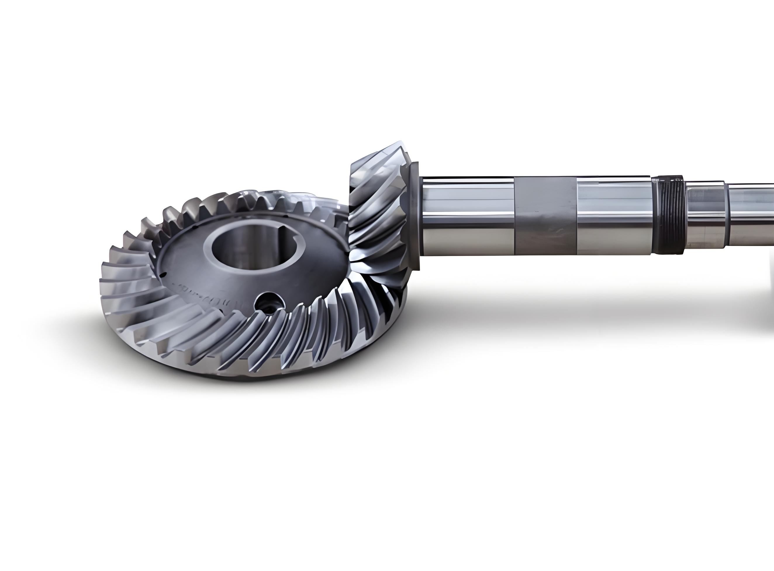
The assembled pair of these spiral bevel gears, representing the core of the nutation drive, is shown in the following visualization. The complex curvature of the double circular-arc tooth flanks is evident, designed to promote favorable contact conditions under load.
Finite Element Modeling and Loaded Contact Analysis
To accurately simulate the contact behavior of the double circular-arc spiral bevel gears under operational conditions, we developed a finite element model using Ansys Workbench. Given the nonlinear nature of gear contact—involving changing contact areas, sliding, and deformation—the FEM provides a robust platform for such analysis. We constructed a model containing seven tooth pairs from both the external and internal spiral bevel gears. This scope balances computational efficiency with the need to capture multi-tooth engagement effects, which are crucial for calculating parameters like contact ratio and load sharing.
The material properties were assigned as typical for high-strength alloy steels used in precision gearing: Young’s modulus \( E = 210 \) GPa, Poisson’s ratio \( \nu = 0.3 \), and density \( \rho = 7850 \) kg/m³. A static structural analysis was performed, as the primary interest lies in the quasi-static contact characteristics at a given instant or over a small rotational increment. The boundary conditions were applied to simulate the nutation drive’s constraints: the external spiral bevel gear was fixed in all degrees of freedom, while the internal spiral bevel gear was only allowed to rotate about its own axis. A constant torque \( T \) was applied to the internal gear, simulating the load. To aid convergence in this nonlinear contact problem, the load was ramped up from zero to its full value over the solution steps.
The contact definition between the tooth flanks of the spiral bevel gears is critical. We defined surface-to-surface contact pairs. A friction coefficient of 0.1 was specified to account for lubricated conditions. The mesh was generated using tetrahedral elements, as they can conform well to the complex curved geometry of the spiral bevel gears. A refined mesh was applied in the potential contact zones to ensure accurate stress resolution. The final finite element model comprised approximately 187,000 elements and 278,000 nodes.
We first analyzed the contact state of a single tooth pair (the middle pair in our model) over one complete meshing cycle. The cycle is defined as the period from when the tooth pair first makes contact to when it finally loses contact. The finite element solution outputs, including contact pressure distribution and contact forces, were extracted at small angular increments of the internal gear. The contact patterns and the corresponding maximum contact stress \( \sigma_{Hmax} \) on the observed tooth flank were recorded. The results reveal a distinct sequence of contact states for these double circular-arc spiral bevel gears. The meshing initiates with a single-point contact on the convex flank near the heel (large end) of the tooth. As the gears rotate, this contact patch moves across the face width. Subsequently, a second contact point appears on the concave flank near the heel, leading to a double-point contact state where both the convex and concave flanks share the load. Finally, the contact on the convex flank is lost, and the tooth pair finishes its meshing cycle with a single-point contact on the concave flank near the toe (small end). The variation of instantaneous maximum contact stress during this cycle exhibits a characteristic curve: it rises during initial single-point contact, reaches a local maximum, then often dips during the double-point contact phase due to increased load-sharing area, and finally peaks again during the final single-point contact phase just before exit. Notably, the absolute maximum contact stress typically occurs on the concave flank near the toe region, identifying it as a critical area for potential pitting or wear failure in these spiral bevel gears.
Influence of Applied Load on Transmission Performance Metrics
Beyond the basic contact state, two key performance metrics for any gear system, including spiral bevel gears, are the contact ratio and the load distribution among simultaneously engaged tooth pairs. We investigated how these metrics are influenced by the magnitude of the applied load.
The contact ratio \( \varepsilon \) is a measure of the average number of tooth pairs in contact during operation. A higher contact ratio generally contributes to smoother motion transfer and lower dynamic loads. In the context of our finite element simulation, for a given constant load, we can determine \( \varepsilon \) by analyzing the contact force history of consecutive tooth pairs. Let \( \Delta T \) be the angular rotation of the driving gear (internal spiral bevel gear) over which a specific tooth pair remains in contact (its meshing cycle). Let \( \Delta t \) be the angular rotation between the instants when two successive tooth pairs initially enter contact. The contact ratio is then calculated as:
$$ \varepsilon = \frac{\Delta T}{\Delta t} $$
By post-processing the FEM results for the contact forces on three adjacent tooth pairs under a baseline load of \( T_0 = 120 \) N·m, we obtained the force versus rotation angle curves. From these curves, \( \Delta T \) and \( \Delta t \) were measured, yielding a contact ratio \( \varepsilon_{T_0} \). To study the load effect, we repeated the analysis for two additional load levels: \( T_1 = 50 \) N·m and \( T_2 = 150 \) N·m. The calculated contact ratios are presented in Table 2.
| Load Torque, \( T \) (N·m) | Measured \( \Delta T \) (deg) | Measured \( \Delta t \) (deg) | Contact Ratio, \( \varepsilon \) |
|---|---|---|---|
| 50 | 27.8 | 14.45 | 1.923 |
| 120 | 33.2 | 14.40 | 2.306 |
| 150 | 36.5 | 14.38 | 2.538 |
The results clearly indicate that the contact ratio of these double circular-arc spiral bevel gears increases with the applied load. This phenomenon can be attributed to elastic deformation. Under higher loads, the teeth deform more, causing the contact zones to elongate and the theoretical lines of contact to spread. This effectively allows tooth pairs to remain in contact for a longer angular duration (\( \Delta T \) increases), while the fundamental angular pitch (\( \Delta t \)) remains nearly constant, leading to a higher \( \varepsilon \). This is a beneficial aspect, as it enhances the load-sharing capability and smoothness of the nutation drive at operational loads.
The load distribution coefficient \( C_j \) quantifies how the total transmitted load is shared among the tooth pairs in contact at any given instant. For the \( j \)-th tooth pair in contact, it is defined as:
$$ C_j = \frac{F_j}{\sum_{k=1}^{n} F_k} $$
where \( F_j \) is the normal contact force on the \( j \)-th pair, \( n \) is the total number of pairs in contact at that instant, and the denominator is the sum of forces on all contacting pairs. A perfectly even load distribution would result in \( C_j = 1/n \). Fluctuations in \( C_j \) indicate uneven loading, which can lead to higher stresses on individual teeth and increased vibration. We calculated the load distribution coefficient for the middle tooth pair over its meshing cycle for the three load levels. The peak value of \( C_j \) during the cycle, denoted \( C_{max} \), is of particular interest as it represents the worst-case load concentration. The findings are summarized in Table 3.
| Load Torque, \( T \) (N·m) | Peak Load Distribution Coefficient, \( C_{max} \) | Approx. Number of Pairs in Contact at Peak |
|---|---|---|
| 50 | 1.000 | ~1 |
| 120 | 0.859 | ~1.16 |
| 150 | 0.788 | ~1.27 |
The data shows that \( C_{max} \) decreases with increasing load. At the lightest load (50 N·m), the peak coefficient is 1.0, implying that for a significant portion of its cycle, the observed tooth pair carries the entire load alone (single-pair contact dominates). As the load increases to 120 N·m and 150 N·m, the peak coefficient drops to 0.859 and 0.788, respectively. This confirms that higher loads induce more elastic deformation, promoting earlier engagement and later disengagement of adjacent teeth, thereby improving multi-pair contact. Consequently, the load is distributed more evenly among a greater number of spiral bevel gear teeth, reducing the burden on any single tooth. This analysis underscores the importance of considering system elasticity when evaluating the performance of heavily loaded spiral bevel gear drives.
Impact of Installation Errors on Contact Characteristics
Practical assembly of a nutation drive with spiral bevel gears inevitably introduces misalignments. Two primary types of installation errors are considered: an offset error \( \Delta C \) along the axis of the internal gear, and a nutation angle error \( \Delta \alpha_n \). These errors disrupt the theoretically perfect relative positioning of the gear axes, potentially altering the contact pattern, increasing stress concentrations, and degrading transmission smoothness. We performed a parametric study using our finite element model to quantify these effects under a constant load of 120 N·m.
The offset error \( \Delta C \) represents a linear displacement of the internal spiral bevel gear along its axis from the ideal position. A positive \( \Delta C \) moves the gears slightly apart, while a negative \( \Delta C \) moves them closer together. The nutation angle error \( \Delta \alpha_n \) represents a deviation from the designed angle between the axes of the external and internal spiral bevel gears. We analyzed cases with \( \Delta C = \pm0.05 \) mm and \( \Delta \alpha_n = \pm0.05^\circ \). For each error case, we examined the resulting tooth contact pattern at the double-point contact phase and at the phase of maximum contact stress. Furthermore, we extracted the peak contact stress \( \sigma_{Hmax}^{peak} \) and the corresponding peak contact force \( F^{peak} \) for the middle tooth pair over its cycle. The results are compiled in Table 4.
| Error Type | Error Value | Peak Contact Stress \( \sigma_{Hmax}^{peak} \) (MPa) | Peak Contact Force \( F^{peak} \) (N) | Contact Pattern Shift |
|---|---|---|---|---|
| None (Reference) | 0 | 1250 | 5850 | Centered on flank |
| Offset Error \( \Delta C \) | +0.05 mm | 1180 | 5520 | Toward transition region |
| Offset Error \( \Delta C \) | -0.05 mm | 1350 | 6320 | Toward edge (toe/heel) |
| Nutation Angle Error \( \Delta \alpha_n \) | +0.05° | 1380 | 6450 | Toward edge (toe/heel) |
| Nutation Angle Error \( \Delta \alpha_n \) | -0.05° | 1160 | 5430 | Toward transition region |
The table reveals distinct and opposite trends for the two error types. A positive offset error (\( \Delta C > 0 \)) slightly reduces the peak contact stress and force compared to the error-free case. The contact pattern shifts towards the central or transition region of the tooth flank. Conversely, a negative offset error (\( \Delta C < 0 \)) increases both peak stress and force significantly, and the contact pattern is displaced towards the tooth edges (either the toe on the concave flank or the heel on the convex flank), leading to edge contact. The effects of nutation angle error are symmetrical but inverse: a positive error (\( \Delta \alpha_n > 0 \)) behaves similarly to a negative offset error, increasing stress and causing edge contact, while a negative error reduces stress and centralizes the contact. This complementary relationship arises because the errors geometrically affect the relative shaft alignment in opposite manners.
Edge contact is particularly detrimental as it concentrates stress on a very small area, dramatically increasing the risk of surface failure and generating vibrations. Therefore, both negative offset errors and positive nutation angle errors are considered unfavorable for the spiral bevel gears’ durability and smooth operation. The sensitivity analysis also extended to the load distribution coefficient. Under unfavorable errors (negative \( \Delta C \) or positive \( \Delta \alpha_n \)), the load distribution becomes more uneven. The peak load distribution coefficient \( C_{max} \) increases, indicating that a single tooth pair bears a disproportionately large share of the total load during part of its cycle. For instance, with \( \Delta C = -0.05 \) mm, \( C_{max} \) rose to approximately 0.92, compared to 0.859 in the error-free case. This exacerbates stress concentrations and can accelerate fatigue. The mathematical relationship between error magnitude and contact performance can be modeled approximately. For small errors, the change in peak contact stress \( \Delta \sigma_H \) can be considered linearly proportional to the error:
$$ \Delta \sigma_H \approx K_C \cdot (\Delta C) + K_\alpha \cdot (\Delta \alpha_n) $$
where \( K_C \) and \( K_\alpha \) are sensitivity coefficients determined from the finite element data. Our results suggest \( K_C \) is negative and \( K_\alpha \) is positive for the defined sign conventions, meaning stress increases with negative \( \Delta C \) and positive \( \Delta \alpha_n \). These findings emphasize the critical need for precise manufacturing and careful assembly control in nutation drives employing double circular-arc spiral bevel gears to mitigate the adverse effects of installation errors.
Conclusions
This comprehensive finite element-based study has elucidated the complex contact characteristics of double circular-arc spiral bevel gears operating within a nutation drive. The unique tooth geometry induces a three-phase meshing cycle: initial single-point contact on the convex flank, followed by a double-point contact phase where both convex and concave flanks share the load, and final single-point contact on the concave flank. The maximum contact stress consistently occurs near the toe region on the concave flank, identifying it as the critical zone for design attention regarding contact fatigue in these spiral bevel gears.
The analysis of load influence reveals advantageous elastic behavior. Increasing the transmitted load enhances the contact ratio and improves load sharing among multiple tooth pairs, as evidenced by a decreasing peak load distribution coefficient. This implies that under typical operating conditions, these spiral bevel gears may perform more smoothly and with better load distribution than predicted by rigid-body theory, a positive attribute for the nutation drive’s performance.
However, the performance is sensitive to assembly inaccuracies. Installation errors, specifically axial offset and nutation angle deviation, can drastically alter the contact pattern, shift it towards the tooth edges, and increase the maximum contact stress and load concentration. Negative offset errors and positive nutation angle errors were found to be particularly detrimental, promoting edge contact and uneven load distribution. Therefore, stringent tolerance control during the assembly of nutation drives incorporating such spiral bevel gears is paramount to ensure expected life and quiet operation.
The methodologies and findings presented here provide a valuable framework for the design and analysis of double circular-arc spiral bevel gears in nutation and other high-precision applications. Future work could explore dynamic effects, the influence of lubrication, and optimization of the double circular-arc profile parameters to further minimize stress and improve the efficiency of these sophisticated spiral bevel gear systems.