
As an engineer specializing in mechanical component durability, I have always been fascinated by the critical role of gears in power transmission systems. Among them, the pair comprising a smaller driving gear (pinion) and a larger driven gear (spur gear) is fundamental. The performance and longevity of this spur and pinion set are paramount to the overall reliability of machinery. One of the most significant processes to enhance their load-bearing capacity and wear resistance is heat treatment, specifically quenching. However, this very process introduces complex thermo-mechanical phenomena leading to residual stresses, which can be detrimental if not properly understood and controlled. This article delves into a detailed finite element analysis of the quenching process for a spur and pinion pair made from 20CrMnTi steel, exploring the evolution of temperature, phase transformation, and the resulting residual stress fields that ultimately define their service life.
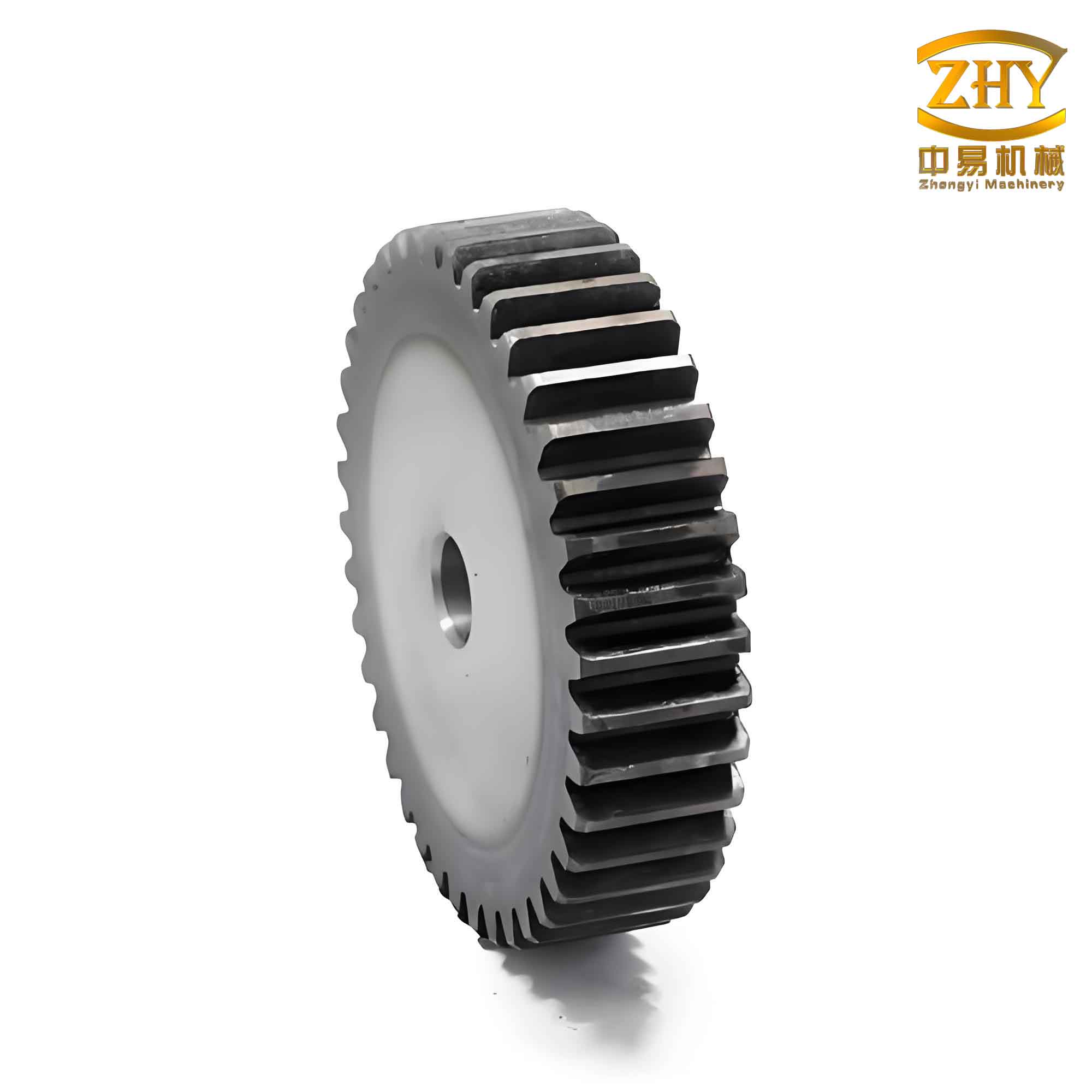
The material of choice for many high-performance transmission components like the spur and pinion is 20CrMnTi. This low-carbon alloy steel is favored for its excellent hardenability and toughness profile. Its chemical composition, primarily involving Chromium, Manganese, and Titanium, allows for the formation of a deep, hard martensitic case during carburizing and quenching while maintaining a tough, ductile core. The success of this spur and pinion set in automotive and heavy machinery applications hinges on achieving an optimal residual stress distribution post-quenching—compressive stresses at the surface are highly desirable for fatigue resistance, while excessive tensile stresses in the subsurface or core can initiate cracks.
| Element | C | Cr | Mn | Ti | Si | Fe |
|---|---|---|---|---|---|---|
| Content | 0.17-0.23 | 1.00-1.30 | 0.80-1.10 | 0.04-0.10 | 0.17-0.37 | Balance |
The quenching process for a spur and pinion is inherently non-uniform. The complex geometry with teeth, web, and bore leads to drastic variations in local cooling rates when immersed in a quenching medium. This non-uniform cooling is the primary source of thermal gradients, which in turn generate thermal stresses. Furthermore, as the steel cools through specific temperature ranges, microstructural phase transformations occur—most notably the transformation from austenite to martensite. This transformation is accompanied by a significant volumetric expansion, introducing additional transformation-induced stresses. The final residual stress state in the spur and pinion is a complex superposition of these thermal and transformation stresses. Accurately predicting this state is crucial for preventing quenching cracks and distortion, and for ensuring the predicted fatigue life of the spur and pinion assembly is achieved in service.
Finite Element Modeling of the Spur and Pinion Quenching Process
To simulate the intricate physics involved, a robust finite element model was developed. The geometry of the spur and pinion pair was defined with the following key parameters, which are critical for meshing and load distribution calculations in later stages of design.
| Parameter | Pinion (Driver) | Spur Gear (Driven) |
|---|---|---|
| Number of Teeth (z) | 36 | 45 |
| Module (m) [mm] | 2 | |
| Pressure Angle (α) [°] | 20 | |
| Face Width (b) [mm] | 30 | |
The model was discretized using a combination of tetrahedral and hexahedral elements, with a refined mesh in the tooth root fillet and flank regions where stress concentrations are expected. A critical aspect of the simulation is defining the material properties as functions of temperature and microstructure. The thermal properties (thermal conductivity, specific heat, density) and mechanical properties (Young’s modulus, yield strength, thermal expansion coefficient) for 20CrMnTi were defined from austenitizing temperatures down to room temperature. Furthermore, Time-Temperature-Transformation (TTT) data or continuous cooling transformation kinetics were incorporated to model the austenite-to-martensite phase change. The latent heat released during transformation was also accounted for in the thermal analysis.
The boundary conditions were set to mimic a two-stage quenching process commonly used in industry to balance hardness and minimize distortion for components like a spur and pinion. The initial condition for the entire gear set was a uniform austenitizing temperature of 860°C.
| Stage | Medium | Medium Temperature | Convective Heat Transfer Coefficient (h) | Approximate Duration |
|---|---|---|---|---|
| 1. Oil Quench | Oil | 80°C | hoil(T) [Variable with temperature] | 600 s |
| 2. Air Cooling | Air | 25°C | hair [Constant] | 1800 s |
Mechanical constraints were applied to simulate the gear’s mounting on a shaft. The inner bore surface of both the spur gear and the pinion was constrained in the radial direction (Ur=0). The side faces of the gears were constrained in the axial direction (Uz=0) to prevent rigid body motion and simulate symmetry or support conditions. The analysis was performed in a sequentially coupled manner: first, a transient heat transfer analysis was conducted to obtain the temperature history T(x,y,z,t) for every node in the model. This temperature history was then imported as a thermal load into a subsequent stress analysis to compute the developing stresses and strains.
Analysis of Transient Temperature Fields in the Spur and Pinion
The temperature evolution within the spur and pinion during quenching is governed by the classical heat conduction equation with convective boundary conditions:
$$
\rho c_p \frac{\partial T}{\partial t} = \nabla \cdot (k \nabla T) + \dot{q}_{latent}
$$
where $\rho$ is density, $c_p$ is specific heat capacity, $k$ is thermal conductivity, and $\dot{q}_{latent}$ is the latent heat generation rate due to phase transformation. The results revealed a pronounced radial temperature gradient from the core to the surface and tooth tips. At the very beginning of the oil quench (t=10s), the surface of the teeth and rim had cooled rapidly to approximately 400°C, while the material in the core and near the bore of both the spur gear and pinion remained close to the initial 860°C. This steep gradient is the primary driver for early-stage thermal stresses.
As quenching progressed, the cooling front moved inwards. By t=60s, the maximum temperature in the gear pair had dropped to around 410°C. At the end of the oil quench stage (t=600s), the entire component had approached the oil temperature, with a maximum temperature near 79°C. The final air cooling stage served to equalize the temperature further, bringing the entire spur and pinion set to near ambient temperature (~74.5°C) by t=1800s. A consistent observation was that the larger spur gear retained slightly higher temperatures in its core compared to the smaller pinion at equivalent time steps, attributable to its greater thermal mass and longer diffusion path.
| Quench Time [s] | Stage | Max Temp. in Pinion [°C] | Max Temp. in Spur Gear [°C] | Primary Location of Max Temp. |
|---|---|---|---|---|
| 0 | Initial | 860 | 860 | Entire Volume |
| 10 | Oil Quench | ~860 | ~860 | Core/Bore Region |
| 60 | Oil Quench | ~410 | ~415 | Core Region |
| 600 | End of Oil Quench | ~79 | ~80 | Core Region |
| 1800 | End of Air Cooling | ~74.5 | ~75.0 | Core Region |
The radial temperature profile showed that the temperature gradient (dT/dr) is highest during the initial rapid cooling phase. As time progresses and the component temperature homogenizes, this gradient diminishes significantly. This temporal behavior of the temperature gradient is directly linked to the evolution of thermal stresses in the spur and pinion.
Evolution of Stresses and Strains: Thermal and Transformation Effects
The total strain rate $\dot{\epsilon}_{total}$ during quenching can be decomposed into several components:
$$
\dot{\epsilon}_{total} = \dot{\epsilon}_{el} + \dot{\epsilon}_{pl} + \dot{\epsilon}_{th} + \dot{\epsilon}_{tr} + \dot{\epsilon}_{tp}
$$
where the subscripts denote elastic, plastic, thermal, transformation-induced volumetric, and transformation-induced plasticity (TRIP) strains, respectively. The thermal strain is calculated as $\epsilon_{th} = \alpha (T – T_{ref})$, where $\alpha$ is the coefficient of thermal expansion. In the early stages of cooling, the surface layer of the spur and pinion teeth contracts more than the hot core, putting the surface in tension and the core in compression. However, if the thermal stress exceeds the temperature-dependent yield strength of the austenite, plastic deformation occurs, altering the stress state.
The most significant event is the martensitic transformation, which initiates at the martensite start temperature (Ms). The transformation strain $\epsilon_{tr}$ is often related to the volume change $\Delta V/V$ and the martensite volume fraction $\xi$:
$$
\epsilon_{tr} = \beta \cdot \xi \quad \text{where } \beta \approx \frac{1}{3} \frac{\Delta V}{V}
$$
For steel, the formation of martensite from austenite results in a volumetric expansion. When the surface transforms first, this expansion is resisted by the untransformed, still ductile austenitic core, leading to compressive stresses at the surface—a highly beneficial outcome for the fatigue performance of the spur and pinion. As cooling proceeds, the core eventually transforms, but its expansion is now constrained by the already hardened and transformed surface layer, which can generate tensile stresses in the core or subsurface regions.
The simulation results clearly captured this complex interplay. During the first 50 seconds of oil quenching, thermal contraction dominated, causing a rapid rise in equivalent (von Mises) stress. As the temperature dropped further and the surface layers yielded, a temporary stress relaxation was observed around 50-200s. Subsequently, as martensitic transformation swept from the surface towards the core, the stress increased sharply again due to transformation-induced expansion. After approximately 500s, the stresses began to stabilize as the phase transformation neared completion and thermal gradients reduced. The final stabilized residual stress state, reached after air cooling, showed a maximum tensile stress of approximately 1.2 GPa located in the subsurface/core region, while the tooth surfaces were in a state of high compressive stress.
| Time Period [s] | Dominating Physical Phenomenon | Radial Stress Profile (Surface vs. Core) | Impact on Final Residual Stress |
|---|---|---|---|
| 0 – 50 | Rapid thermal contraction of surface | Surface in tension, Core in compression | Sets initial plastic strain pattern |
| 50 – 200 | Plastic yielding and thermal gradient reduction | Stress relaxation/reversal | Reduces early thermal stress peaks |
| 200 – 600 | Martensitic transformation (surface to core) | Surface goes into compression, Core tension rises | Establishes beneficial surface compression |
| 600 – 1800 | Core transformation completion & thermal equalization | Profile stabilizes | Finalizes residual stress distribution |
A critical finding from the analysis of the spur and pinion pair was a stress reversal phenomenon related to timing. For times less than approximately 600 seconds (during active oil quenching), the stress magnitude at the external regions (teeth, rim) was generally higher than at the internal regions (near the bore). After 600 seconds (during and after air cooling), this relationship inverted, with the internal regions exhibiting higher residual stress magnitudes than the external regions. This is a direct consequence of the sequence of phase transformation: the exterior transforms first, becoming hard and compressive, while the later-transforming interior expands against this hard shell, building up tensile residual stress.
Discussion on Phase Transformation Influence and Model Considerations
The results underscore that ignoring phase transformation in the simulation of spur and pinion quenching would lead to a fundamentally incorrect and non-conservative prediction of residual stresses. A model considering only thermal stresses would predict high tensile stresses at the surface due to contraction, which contradicts the well-known beneficial compressive layer imparted by hardening. The incorporation of transformation-induced strain and volume change is therefore non-negotiable for accurate modeling.
The accuracy of the model hinges on several key inputs: the temperature-dependent heat transfer coefficient (HTC) for the quenching oil, and the kinetics of the phase transformation. The HTC is not constant; it varies dramatically with surface temperature, going through the vapor blanket, nucleate boiling, and convective stages. Using a constant or poorly characterized HTC profile can significantly alter the predicted cooling curves and thus the stress evolution. Similarly, the accuracy of the CCT diagram and the model for calculating martensite volume fraction (e.g., using the Koistinen-Marburger equation, $\xi = 1 – \exp[-\kappa(M_s – T)]$) is critical.
Furthermore, the interaction between the spur gear and the pinion during quenching was not considered in this thermal-stress analysis, as they were modeled as separate components with no contact definition during the heat treatment process. In reality, if gears are quenched while meshed or in close proximity, heat transfer and constraint between them could alter local cooling rates and stress states. This presents an area for more advanced coupled analysis.
Conclusion
The finite element analysis of the quenching process for a 20CrMnTi spur and pinion pair provides deep insights into the transient thermo-metallurgical-mechanical events that shape their final state. The temperature evolution is characterized by high radial gradients during initial rapid cooling, which gradually diminish as the component temperature homogenizes. The resulting stress state is a complex, time-dependent product of competing thermal contraction and phase transformation expansion. The sequence of martensite formation, starting at the surface and progressing inward, is instrumental in generating a final residual stress profile with desirable compressive stresses at the critical tooth surface and potentially high tensile stresses in the core. The observed stress reversal, where the internal stress surpasses the external stress after the majority of transformation is complete, is a key characteristic of through-hardening components like this spur and pinion set. This comprehensive numerical approach, which faithfully accounts for temperature-dependent material properties, phase transformation kinetics, and realistic boundary conditions, is an indispensable tool for optimizing quenching processes to minimize distortion, prevent cracking, and maximize the fatigue life and reliability of critical gearing components such as the spur and pinion.