
In my extensive experience with the maintenance of heavy-duty machine tools, the failure of critical transmission components like a pair of spiral bevel gears can bring production to a complete halt. The scenario is common: a vital spiral bevel gear set in the feed system of a large CNC boring and milling machine fails. The original manufacturer has no stock, and the lead time for a new set is prohibitively long. In such situations, the only path to a swift machine restoration is to meticulously measure the failed parts and produce the drawings for local manufacturing. This process of reverse-engineering through measurement is a cornerstone of effective machine tool repair, and its accuracy directly determines the performance and longevity of the replacement spiral bevel gears. This guide details my methodological approach to determining the geometric parameters of a spiral bevel gear pair, ensuring the newly machined gears will mesh perfectly and restore the machine’s functionality.
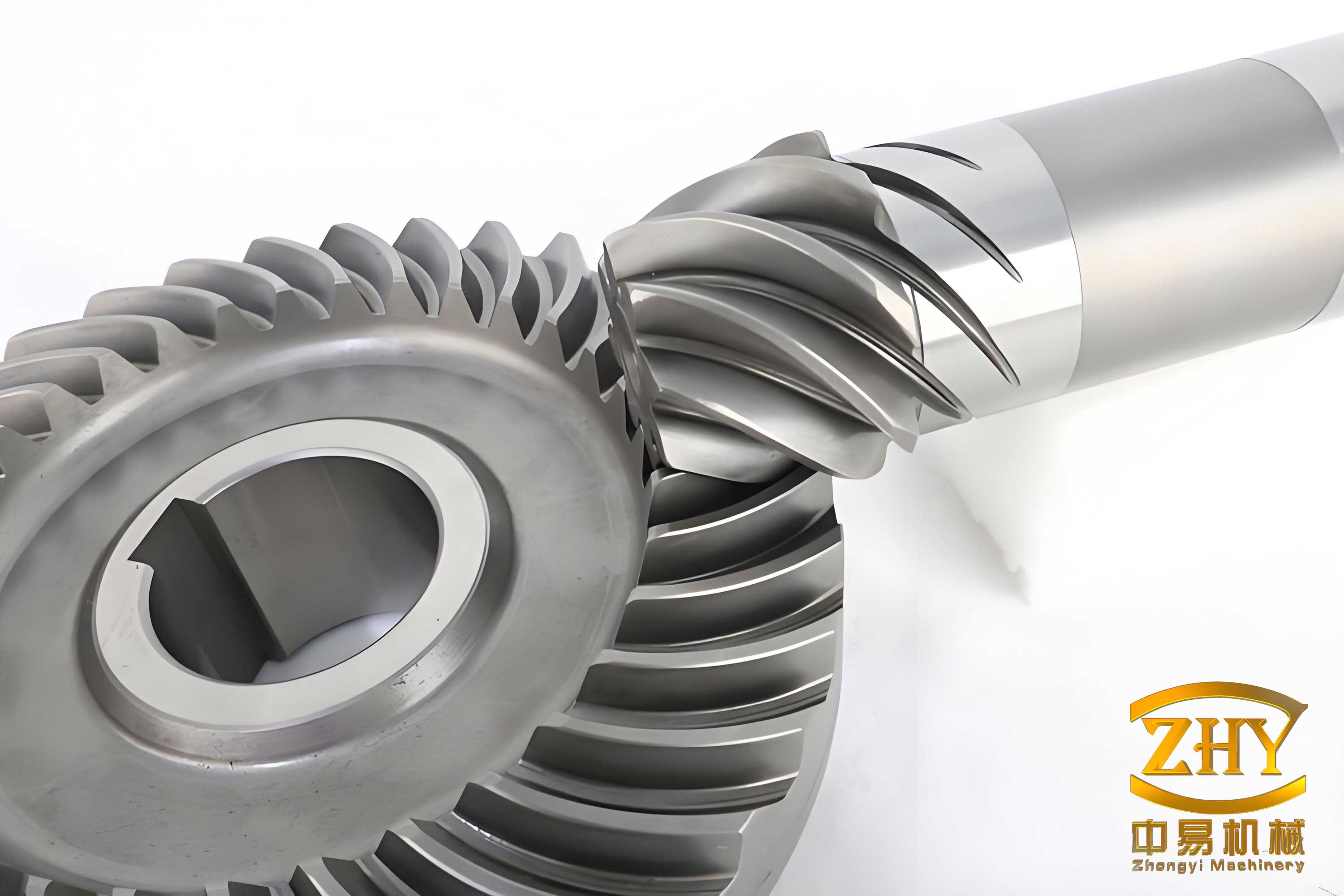
The specific subject of this measurement exercise is a pair of spiral bevel gears from the feed drive of a large CNC planer-type boring and milling machine. These gears are essential for converting rotational motion between intersecting shafts, typically at 90 degrees, and their complex geometry requires a systematic measurement approach. The primary challenge lies in the fact that not all parameters can be measured directly from a worn or damaged gear; many must be derived through calculation based on standard tooth systems and the measurable parameters of its mating gear. This is why it is always preferable, and far simpler, to measure and replace the spiral bevel gear pair as a set.
Step 1: Determining the Tooth System and Mean Spiral Angle (βm)
The first critical step is identifying the tooth system standard. Common systems for spiral bevel gears include Gleason, Klingelnberg (Cyclo-Palloid), and Oerlikon. Each has defining characteristic parameters for pressure angle, addendum coefficient, and spiral angle. The mean spiral angle, βm, is particularly difficult to measure accurately on a single gear, especially if it is worn or modified. Among various methods like the rolling impression method, sine bar principle, or ball measurement technique, I often use the practical rolling impression method for an initial estimate. For the gear pair in question, this method indicated a spiral angle of approximately 35°. Based on this and common industry standards for machine tool drives, I identified the gears as conforming to the Gleason system with an equal dedendum design. The standard parameters for this system are thus assumed:
- Mean Spiral Angle, βm = 35°
- Pressure Angle, α = 20°
- Addendum Coefficient, ha* = 0.85
- Bottom Clearance Coefficient, c* = 0.188
This identification is crucial as it provides the foundational coefficients for all subsequent calculations of the spiral bevel gear geometry.
Step 2: Determining Module (m) and Reference Diameters (d)
The module is the fundamental metric defining gear tooth size. Direct measurement of the pitch diameter on a bevel gear is impractical. Therefore, we start by counting teeth and measuring the outside (tip) diameters as accurately as possible.
- Pinion (z1): Measured tooth count, z1 = 20. Measured tip diameter, da1_meas = 85.6 mm.
- Gear (z2): Measured tooth count, z2 = 25. Measured tip diameter, da2_meas = 104.2 mm.
The gear ratio is: $$u = \frac{z_2}{z_1} = \frac{25}{20} = 1.25$$
An initial estimate for the module (m) can be derived from the approximate relationship for bevel gears: da ≈ m(z + 2 cos δ). As the pitch angles (δ) are not yet known, a simplified estimation using a parallel spur gear analogy gives a starting point:
$$m_{est1} = \frac{d_{a1\_meas}}{z_1 + 2} = \frac{85.6}{22} \approx 3.89 \text{ mm}$$
$$m_{est2} = \frac{d_{a2\_meas}}{z_2 + 2} = \frac{104.2}{27} \approx 3.86 \text{ mm}$$
The values are close, averaging around 3.875 mm. Standard module values must be consulted. The closest standard module is m = 4 mm. We will verify this choice through later calculations. The reference diameters are then:
$$d_1 = m \cdot z_1 = 4 \times 20 = 80.0 \text{ mm}$$
$$d_2 = m \cdot z_2 = 4 \times 25 = 100.0 \text{ mm}$$
Step 3: Determining Profile Shift Coefficients (x) and Tangential Shift (xτ)
Gleason system spiral bevel gears utilize profile shift (often called “offset” or “addendum modification”) to balance specific sliding and strength between the pinion and gear. The sum of the profile shift coefficients is zero (x1 + x2 = 0), but they are not equal. For the Gleason equal dedendum system, the pinion has a positive shift and the gear a negative one.
a) Profile Shift Coefficients (x1, x2):
These can be determined either by calculation or by using Gleason’s empirical tables based on the gear ratio (u).
Calculation (Approximate Formula):
$$x_1 \approx 0.39 \left(1 – \frac{1}{u^2}\right) = 0.39 \left(1 – \frac{1}{1.25^2}\right) = 0.39 (1 – 0.64) = 0.1404$$
Thus, x1 ≈ +0.14 and x2 = -x1 = -0.14.
Table Lookup: For a gear ratio u = 1.25, standard Gleason tables indicate a profile shift coefficient. Consulting such a table confirms the value.
| Gear Ratio (u) | Profile Shift Coeff. (x1) |
|---|---|
| 1.23 ~ 1.26 | 0.14 |
| 1.26 ~ 1.28 | 0.15 |
Both methods confirm x1 = +0.14, x2 = -0.14.
b) Tangential Shift Coefficient (xτ):
This coefficient adjusts the tooth thickness and is also determined from Gleason charts based on the number of teeth in the pinion (z1). For z1 = 20, the standard value is xτ1 ≈ +0.017. The gear’s coefficient is the negative: xτ2 = -0.017.
Step 4: Determining Pitch Cone Angles (δ) and Cone Distance (R)
For a shaft angle Σ = 90°, which is standard for most applications like this feed drive, the pitch cone angles are simple trigonometric functions of the tooth count ratio.
$$ \tan \delta_1 = \frac{z_1}{z_2} = \frac{1}{u} = \frac{1}{1.25} = 0.8$$
$$ \delta_1 = \arctan(0.8) \approx 38.6598^\circ \text{ or } 38^\circ 40’$$
$$ \delta_2 = \Sigma – \delta_1 = 90^\circ – 38^\circ 40′ = 51^\circ 20’$$
The cone distance (R), analogous to the center distance in parallel axis gears, is calculated from the reference diameters and pitch angles:
$$ R = \frac{d_1}{2 \sin \delta_1} = \frac{d_2}{2 \sin \delta_2} $$
$$ R = \frac{80.0}{2 \times \sin(38.6598^\circ)} = \frac{80.0}{2 \times 0.6248} \approx 64.02 \text{ mm}$$
This value can also be obtained from standard tables that provide R for a module of 1 mm, which is then multiplied by the actual module. For z1=20 and z2=25, the tabulated R/m value is approximately 16.005, giving R = 16.005 * 4 = 64.02 mm, confirming our calculation.
Step 5: Determining Addendum (ha), Dedendum (hf), and Whole Depth (h)
Using the identified coefficients (ha*, c*), the module (m), and the profile shift coefficients (x), we can now calculate the key tooth dimensions.
Whole Depth:
$$ h = (2h_a^* + c^*) \cdot m = (2 \times 0.85 + 0.188) \times 4 = (1.7 + 0.188) \times 4 = 7.552 \text{ mm}$$
Addendum:
$$ h_{a1} = (h_a^* + x_1) \cdot m = (0.85 + 0.14) \times 4 = 3.96 \text{ mm}$$
$$ h_{a2} = (h_a^* + x_2) \cdot m = (0.85 – 0.14) \times 4 = 2.84 \text{ mm}$$
Dedendum:
$$ h_{f1} = h – h_{a1} = 7.552 – 3.96 = 3.592 \text{ mm}$$
$$ h_{f2} = h – h_{a2} = 7.552 – 2.84 = 4.712 \text{ mm}$$
Step 6: Calculating Tip Diameters (da) and Verifying Module Choice
Now we can calculate the theoretical tip diameters using the precise geometry of the spiral bevel gear. This serves as a critical check against our initial measurements and confirms the chosen module.
$$ d_{a1} = d_1 + 2h_{a1} \cos \delta_1 = 80.0 + 2 \times 3.96 \times \cos(38.6598^\circ) $$
$$ d_{a1} = 80.0 + 7.92 \times 0.7807 \approx 80.0 + 6.18 = 86.18 \text{ mm}$$
$$ d_{a2} = d_2 + 2h_{a2} \cos \delta_2 = 100.0 + 2 \times 2.84 \times \cos(51.333^\circ) $$
$$ d_{a2} = 100.0 + 5.68 \times 0.6248 \approx 100.0 + 3.55 = 103.55 \text{ mm}$$
Comparing these calculated values (da1=86.18 mm, da2=103.55 mm) with the original measurements (85.6 mm and 104.2 mm) shows slight discrepancies. These are expected and acceptable due to manufacturing tolerances, wear on the original parts, and measurement uncertainty. The consistency confirms that m=4 mm and the chosen coefficients are correct for this spiral bevel gear pair.
Step 7: Determining Addendum and Dedendum Angles (θa, θf)
These angles define the taper of the tooth flank from the pitch cone to the tip and root cones.
Dedendum Angles:
$$ \tan \theta_{f1} = \frac{h_{f1}}{R} = \frac{3.592}{64.02} \approx 0.0561 \Rightarrow \theta_{f1} \approx 3.21^\circ \text{ or } 3^\circ 13’$$
$$ \tan \theta_{f2} = \frac{h_{f2}}{R} = \frac{4.712}{64.02} \approx 0.0736 \Rightarrow \theta_{f2} \approx 4.21^\circ \text{ or } 4^\circ 13’$$
For the Gleason equal dedendum system, the addendum angle of one member equals the dedendum angle of its mate:
$$ \theta_{a1} = \theta_{f2} \approx 4^\circ 13’$$
$$ \theta_{a2} = \theta_{f1} \approx 3^\circ 13’$$
Step 8: Determining Tip and Root Cone Angles (δa, δf)
These angles are essential for manufacturing the gear blanks and for setting up the gear cutting machine.
Tip Cone Angles:
$$ \delta_{a1} = \delta_1 + \theta_{a1} = 38^\circ 40′ + 4^\circ 13′ = 42^\circ 53’$$
$$ \delta_{a2} = \delta_2 + \theta_{a2} = 51^\circ 20′ + 3^\circ 13′ = 54^\circ 33’$$
Root Cone Angles:
$$ \delta_{f1} = \delta_1 – \theta_{f1} = 38^\circ 40′ – 3^\circ 13′ = 35^\circ 27’$$
$$ \delta_{f2} = \delta_2 – \theta_{f2} = 51^\circ 20′ – 4^\circ 13′ = 47^\circ 07’$$
Step 9: Determining Outer Cone Distance (AK)
Also known as the apex to crown distance, this dimension is crucial for the axial positioning of the gear during assembly and for blank dimensioning.
$$ A_{K1} = R \cos \delta_1 – h_{a1} \sin \delta_1 $$
$$ A_{K1} = 64.02 \times \cos(38.6598^\circ) – 3.96 \times \sin(38.6598^\circ) $$
$$ A_{K1} = 64.02 \times 0.7807 – 3.96 \times 0.6248 \approx 49.98 – 2.47 = 47.51 \text{ mm}$$
$$ A_{K2} = R \cos \delta_2 – h_{a2} \sin \delta_2 $$
$$ A_{K2} = 64.02 \times \cos(51.333^\circ) – 2.84 \times \sin(51.333^\circ) $$
$$ A_{K2} = 64.02 \times 0.6248 – 2.84 \times 0.7807 \approx 40.00 – 2.22 = 37.78 \text{ mm}$$
Step 10: Compiling Data for Manufacturing
All calculated parameters are now synthesized into comprehensive data tables that accompany the detailed part drawings. These tables provide the gear manufacturer with all necessary information to produce a functional spiral bevel gear pair.
| Parameter | Symbol | Value | Notes |
|---|---|---|---|
| Tooth System | – | Gleason | Equal Dedendum |
| Module | m | 4 mm | |
| Number of Teeth | z1 | 20 | |
| Mean Spiral Angle | βm | 35° | |
| Spiral Direction | – | Left Hand | |
| Pressure Angle | α | 20° | |
| Profile Shift Coefficient | x1 | +0.14 | |
| Tangential Shift Coefficient | xτ1 | +0.017 | |
| Whole Depth | h | 7.55 mm | |
| Mating Gear Teeth | z2 | 25 | Right Hand |
| Parameter | Symbol | Value | Notes |
|---|---|---|---|
| Tooth System | – | Gleason | Equal Dedendum |
| Module | m | 4 mm | |
| Number of Teeth | z2 | 25 | |
| Mean Spiral Angle | βm | 35° | |
| Spiral Direction | – | Right Hand | |
| Pressure Angle | α | 20° | |
| Profile Shift Coefficient | x2 | -0.14 | |
| Tangential Shift Coefficient | xτ2 | -0.017 | |
| Whole Depth | h | 7.55 mm | |
| Mating Gear Teeth | z1 | 20 | Left Hand |
Conclusion and Key Considerations
The successful measurement and redrawing of a spiral bevel gear set hinge on a methodical approach that blends direct measurement with deductive calculation based on established tooth systems. The most critical lesson is that for complex gears like a spiral bevel gear, measuring a single member in isolation is fraught with difficulty. Parameters like the spiral angle and various shift coefficients are deeply interlinked. Therefore, the process is vastly simplified and the result is guaranteed to be more accurate when the mating pair is available for measurement together. This allows for cross-verification of parameters and ensures the new pair will mesh correctly without noise or premature wear. Every directly measurable parameter—tooth count, tip diameter, face width, and spiral angle estimate—must be recorded with the highest possible precision, as they form the immutable foundation from which all other critical dimensions of the spiral bevel gear are derived. This rigorous process transforms a failed component from a production-stopping problem into a solvable engineering task, enabling the rapid return of critical machinery to service.