
In the realm of mechanical engineering, spiral bevel gears stand out as critical components due to their superior transmission stability and high load-bearing capacity. These gears are extensively employed in demanding sectors such as aerospace, automotive, and heavy machinery. However, the intricate and complex geometry of spiral bevel gears presents significant manufacturing challenges. Traditional methods rely heavily on iterative trial cuts and adjustments, which are time-consuming and costly. To overcome these hurdles, simulation technology has emerged as a pivotal tool, enabling the virtual modeling and analysis of the entire machining process. In this article, I will comprehensively explore the current state of simulation technology for spiral bevel gear machining, encompassing both geometric and physical simulation aspects. I will delve into the underlying principles, review the extensive research landscape, identify prevailing limitations, and forecast future trends, all while emphasizing the central role of spiral bevel gears in this discourse.
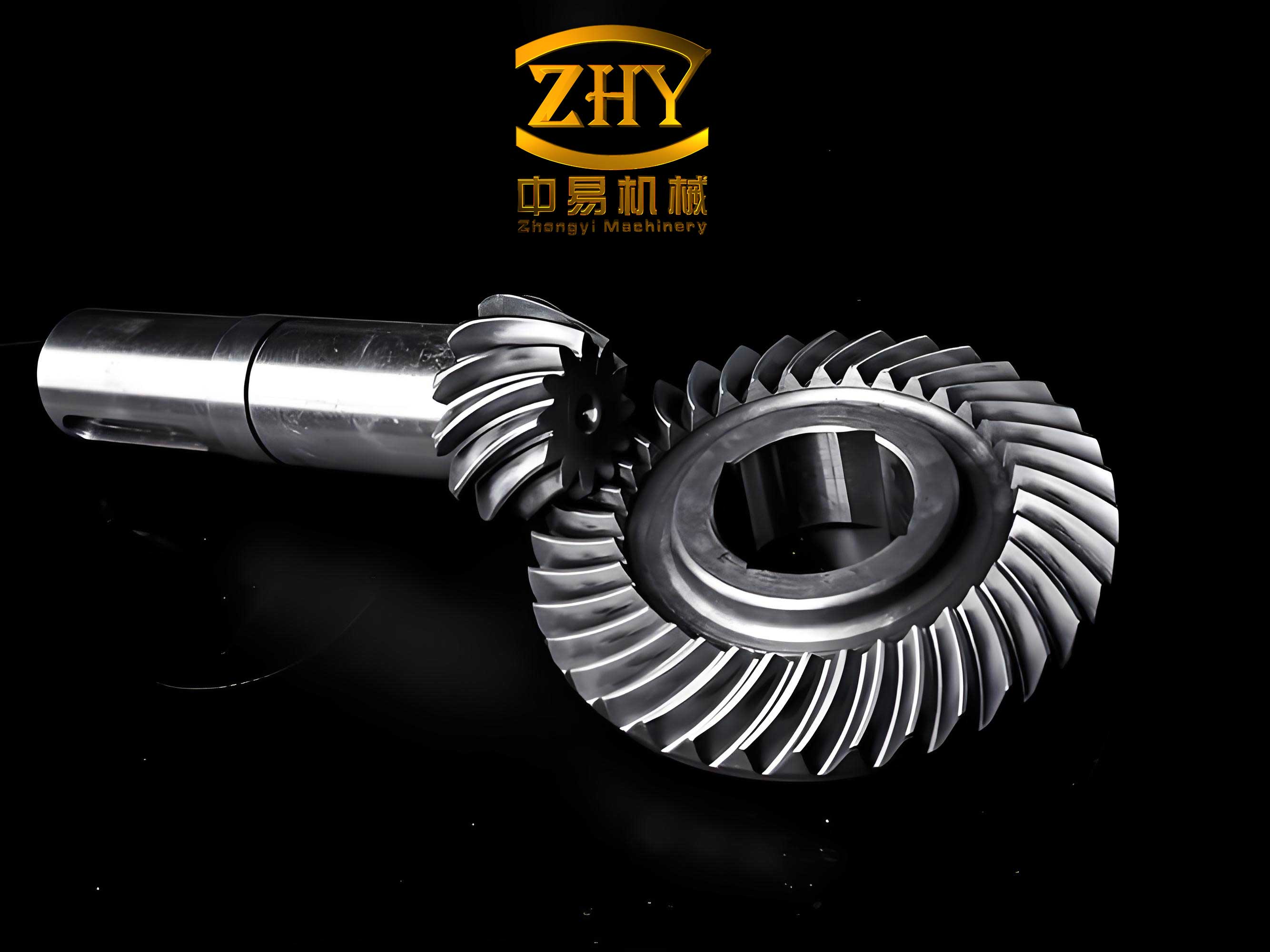
The fundamental machining principle for spiral bevel gears is based on the concept of a “hypothetical generating gear.” This method simulates the meshing action between a theoretical crown gear and the workpiece gear blank. The cutter, representing a tooth of this generating gear, moves relative to the blank to carve out the complex tooth flank. The basic kinematic relationship can be expressed mathematically. Let us define a coordinate system attached to the gear blank and another to the cutter. The surface of the cutter is represented parametrically as $\mathbf{S}_c(u, v)$. The motion of the cutter relative to the blank, governed by the machine tool axes, is described by a series of homogeneous transformation matrices. For a given machine setting, the family of cutter surfaces in the blank coordinate system is given by:
$$\mathbf{F}(\theta, u, v) = \mathbf{T}(\theta) \cdot \mathbf{S}_c(u, v)$$
where $\mathbf{T}(\theta)$ is the 4×4 transformation matrix dependent on the machine motion parameter $\theta$ (often related to the rotation of the workpiece). The envelope of this family of surfaces, which constitutes the machined gear tooth surface, is found by solving the equation:
$$\frac{\partial \mathbf{F}}{\partial \theta} \cdot \left( \frac{\partial \mathbf{F}}{\partial u} \times \frac{\partial \mathbf{F}}{\partial v} \right) = 0$$
This equation represents the condition for tangency between the cutter surface and its envelope. Virtual machining technology leverages this principle by digitally simulating these kinematics. It creates a virtual environment that replicates the CNC machine tool, the cutter, and the blank, allowing for the simulation of the material removal process without physical intervention. The core of geometric simulation lies in discretizing this continuous process. The machining time is divided into small intervals. In each interval, the relative position and orientation of the cutter model and the blank model are updated according to the NC code or machine adjustment parameters. A Boolean subtraction operation is then performed, removing the volume occupied by the cutter from the blank model. The cumulative result of these operations across all intervals yields a 3D digital model of the machined spiral bevel gear. This model can be used for visualization, interference checking, and as input for further analysis like Tooth Contact Analysis (TCA).
The research into geometric simulation for spiral bevel gears has been extensive and varied, employing different software platforms and algorithmic approaches. The table below summarizes a selection of key methodologies and their characteristics found in the literature.
| Core Approach | Primary Software/Platform | Key Algorithmic Feature | Typical Output | Noted Advantages & Challenges |
|---|---|---|---|---|
| Boolean Subtraction with Parametric CAD | AutoCAD (VBA, C++), SolidWorks API | Discrete time-step positioning and solid Boolean operations. | 3D solid model of the gear. | Intuitive; direct visualization. Limited precision, computationally heavy for fine details. |
| NURBS Surface Reconstruction | CATIA, Custom C++/OpenGL | Virtual machining to generate point cloud, followed by NURBS fitting. | Precise NURBS representation of the tooth flank. | High precision suitable for CAE; mathematical complexity in surface fitting. |
| Z-buffer / Discrete Layer Methods | Custom graphics engines | Model slicing into layers (z-buffers) and 2D boolean operations per layer. | Voxelized or polygonal mesh model. | Faster computation for complex motions; potential loss of geometric accuracy. |
| Kinematic Modeling & Direct Surface Calculation | MATLAB, Python with analytical models | Solving the envelope equation directly to calculate surface points. | Cloud of discrete points on the theoretical tooth surface. | High analytical accuracy; requires deep mathematical derivation for each gear type. |
| Commercial CAM Simulation | VERICUT, Siemens NX | Integrated G-code interpreter and material removal simulation. | Simulated workpiece and NC program verification. | High fidelity to actual machine tool; often a black-box process for specific gear geometry generation. |
A mathematical formulation common to many discrete simulation methods is the “layer-slicing” algorithm. The gear blank is conceptually sliced into thin layers perpendicular to its axis. For each layer (a circle or annulus), the intersection with the swept volume of the cutter is computed at each simulation step. Let the blank layer at height $z_i$ be defined by its inner and outer radii, $R_{in}(z_i)$ and $R_{out}(z_i)$. The cutter profile at time $t_j$, transformed into the blank coordinate system, is represented by a closed curve $C(t_j, z_i)$. The remaining material in the layer after the cut is the set difference:
$$Layer_{final}(z_i) = \bigcap_{j} \left( Layer_{initial}(z_i) \setminus C(t_j, z_i) \right)$$
where $\setminus$ denotes the geometric subtraction. The union of all processed layers reconstructs the 3D gear tooth space. The accuracy of this spiral bevel gear model depends critically on the fineness of the time discretization $\Delta t$ and the layer thickness $\Delta z$. Furthermore, the cutter geometry itself is crucial. For a face-milling cutter, the cutting edge is often modeled as a straight line or a circular arc on the tool face. The coordinates of a point on the cutting edge in the tool coordinate system $(X_t, Y_t, Z_t)$ can be given by:
$$
\begin{aligned}
X_t &= R_c \cdot \sin(\psi) \\
Y_t &= R_c \cdot \cos(\psi) \\
Z_t &= \frac{P}{2\pi} \cdot \psi \quad \text{(for a helical blade)}
\end{aligned}
$$
where $R_c$ is the cutter radius, $\psi$ is the angular position on the cutter, and $P$ is the pitch parameter for helical blades. This tool model is then subjected to the complex multi-axis motion of the spiral bevel gear machining center. The transformation for a 5-axis CNC machine typically involves rotations about two axes (e.g., cradle tilt and swivel) and translations along three axes, compounded with the workpiece rotation. The general transformation matrix for such a system is complex but can be decomposed into a chain of simpler rotations and translations:
$$\mathbf{T}_{total} = \mathbf{T}_{trans}(X, Y, Z) \cdot \mathbf{R}_x(\alpha) \cdot \mathbf{R}_y(\beta) \cdot \mathbf{R}_z(\gamma) \cdot \mathbf{T}_{tool}$$
Here, $\mathbf{R}_x$, $\mathbf{R}_y$, $\mathbf{R}_z$ are rotation matrices about the respective axes, and $\alpha, \beta, \gamma$ are angles derived from machine settings like machine root angle, swivel angle, and work gear rotation. The successful geometric simulation of a spiral bevel gear hinges on the precise implementation of this kinematic chain.
While geometric simulation verifies shape and path, physical simulation aims to reveal the underlying thermo-mechanical phenomena during the cutting of spiral bevel gears. This involves modeling cutting forces, temperatures, stresses, strains, and tool wear using Finite Element Analysis (FEA). The governing equations for a coupled thermo-mechanical analysis are the energy balance equation and the equilibrium equations. The heat generation in the primary shear zone and at the tool-chip interface is a critical factor. The heat flux $q$ entering the workpiece and tool can be estimated from the cutting power:
$$P_c = F_c \cdot V_c$$
$$q = \eta \cdot \frac{P_c}{A_c}$$
where $F_c$ is the main cutting force, $V_c$ is the cutting speed, $\eta$ is the heat partition coefficient (determined experimentally or from models like Hahn’s model), and $A_c$ is the contact area. The transient heat conduction in the workpiece is governed by:
$$\rho c_p \frac{\partial T}{\partial t} = \nabla \cdot (k \nabla T) + \dot{q}_{gen}$$
where $\rho$ is density, $c_p$ is specific heat, $k$ is thermal conductivity, $T$ is temperature, and $\dot{q}_{gen}$ is the internal heat generation rate per unit volume from plastic deformation. Simultaneously, the mechanical deformation is modeled using a material constitutive law that often incorporates thermal softening and strain-rate hardening, such as the Johnson-Cook model:
$$\sigma = \left[ A + B \varepsilon^n \right] \left[ 1 + C \ln \left( \frac{\dot{\varepsilon}}{\dot{\varepsilon}_0} \right) \right] \left[ 1 – \left( \frac{T – T_{room}}{T_{melt} – T_{room}} \right)^m \right]$$
Here, $\sigma$ is the flow stress, $\varepsilon$ is the equivalent plastic strain, $\dot{\varepsilon}$ is the strain rate, $A$, $B$, $C$, $n$, $m$ are material constants, $T_{room}$ is room temperature, and $T_{melt}$ is the melting temperature. The finite element simulation of spiral bevel gear machining requires a 3D model of the cutting process. Due to the complexity and computational cost, simulations are often performed for a single tooth slot or even a segment of the cut. The following table categorizes key aspects and findings from research on physical simulation for spiral bevel gear processes.
| Simulation Focus | Software Used | Modeled Process | Key Outputs & Findings | Critical Model Parameters |
|---|---|---|---|---|
| Milling Force & Temperature | DEFORM-3D, ABAQUS | Single/multiple tooth milling of a gear slot. | Time-varying cutting force signals, temperature distribution on chip and tool, stress concentration zones. | Friction coefficient at tool-chip interface, material flow stress constants, heat transfer coefficients. |
| Grinding Temperature & Residual Stress | ANSYS, Custom FEA codes | Grinding of hardened spiral bevel gear tooth flanks. | 3D temperature field, prediction of residual stress profiles (compressive on surface, tensile subsurface), effect of wet vs. dry grinding. | Grinding heat flux distribution, material removal rate, cooling conditions. |
| Tool Wear Prediction | Third Wave AdvantEdge, Usui Wear Model | Progressive wear of the face-mill cutter inserts. | Flank and crater wear land evolution over simulated cutting time, correlation with cutting parameters. | Archard wear constants, tool coating properties, chip flow characteristics. |
| Microstructure & Phase Transformation | Specialized coupled codes | Hardening process or thermal damage during grinding. | Prediction of white layer formation, altered microstructure depth, hardness gradients. | Phase transformation kinetics models, carbon diffusion data. |
The simulation of the milling process for spiral bevel gears often employs an Arbitrary Lagrangian-Eulerian (ALE) formulation or a pure Lagrangian approach with element deletion to model chip separation. The chip separation criterion is vital; common methods include a critical plastic strain criterion or a geometrical distance-based criterion. The friction at the tool-chip interface is typically modeled using a modified Coulomb law: $\tau = \mu \sigma_n$ for low normal stress, transitioning to a constant shear stress $\tau = \tau_{max}$ at high normal stress, where $\tau$ is the frictional shear stress, $\sigma_n$ is the normal stress, and $\mu$ is the coefficient of friction. The complexity of simulating the full machining cycle for a spiral bevel gear is immense. Therefore, studies often simplify by assuming orthogonal cutting conditions locally or by simulating a representative 2D cross-section. However, the true value of physical simulation for spiral bevel gears lies in its ability to optimize process parameters. For instance, one can run simulations to understand the effect of cutting speed ($V_c$), feed per tooth ($f_z$), and depth of cut ($a_p$) on the following response variables, which can be formulated as an optimization problem:
Minimize: Tool Wear Rate (TWR) and Surface Residual Stress ($\sigma_{res}$)
Subject to constraints: Cutting Force ($F_c$) < F_max, Temperature ($T_{max}$) < T_critical
With design variables: $V_c$, $f_z$, $a_p$ within practical ranges.
Despite significant advances, several challenges and open questions persist in the simulation of spiral bevel gear machining. The table below systematically outlines the main problems and potential future directions.
| Aspect | Current Problems & Limitations | Future Trends & Research Needs |
|---|---|---|
| Geometric Simulation Fidelity | Models often lack the precision required for high-fidelity TCA and LTCA. Reliance on commercial CAD kernels limits openness and customization. Simulation of non-generating methods (e.g., Formate) is less developed. | Development of open-source, high-precision geometric kernels specifically for gear geometry. Enhanced algorithms for direct calculation of the envelope surface with controlled error bounds. Extension of simulation frameworks to cover the full spectrum of spiral bevel gear manufacturing methods. |
| Computational Efficiency | High-fidelity 3D boolean operations for the entire gear are computationally prohibitive. Real-time simulation with realistic graphics (VR environment) is not yet achieved. | Adoption of GPU-accelerated computing and advanced data structures (e.g., octrees) for faster geometric processing. Integration of virtual reality (VR) and augmented reality (AR) for immersive, real-time machine setup and verification. |
| Physical Simulation Depth | Extreme simplification of the actual 5-axis milling kinematics in FEA models. Lack of accurate material models for gear steels under the high strain-rate and temperature conditions of cutting. Scarcity of simulation studies for the complete machining cycle of a spiral bevel gear. | Development of coupled multi-physics FEA models that fully incorporate the complex tool path kinematics of 5-axis spiral bevel gear machining. Extensive material characterization under machining conditions to feed constitutive models. Multi-scale modeling approaches linking micro-scale phenomena (grain structure) to macro-scale gear performance. |
| Integration & Digital Thread | Geometric and physical simulations are often disconnected silos. The digital model from simulation is not seamlessly integrated with downstream processes like measurement and performance prediction. | Creation of a comprehensive digital twin for the spiral bevel gear manufacturing process. This twin would integrate geometric simulation, physical simulation, metrology data, and operational data to enable predictive quality control and closed-loop optimization of the manufacturing process. |
| Model Validation & Standardization | Lack of standardized benchmarks and validation protocols for spiral bevel gear simulation software. Difficulties in obtaining detailed experimental data (e.g., transient temperature and stress fields) for model calibration. | Establishment of industry-accepted benchmark cases for spiral bevel gear simulation. Promotion of collaborative research to generate high-quality experimental datasets using advanced in-situ measurement techniques (e.g., high-speed thermography, embedded sensors). |
The mathematical formulation for a future integrated digital twin could involve a state-space representation where the gear manufacturing process is the system. The state vector $\mathbf{x}$ might include parameters like tool wear state, gear geometry deviations, and residual stress field. The control inputs $\mathbf{u}$ are the machining parameters (speeds, feeds, machine adjustments). The output $\mathbf{y}$ is the measured gear quality (geometry, surface finish, hardness). A model predictive control (MPC) scheme could then be used to optimize $\mathbf{u}$ to keep $\mathbf{y}$ within specifications, using the simulation models as the predictive plant model:
$$
\begin{aligned}
\mathbf{x}_{k+1} &= f(\mathbf{x}_k, \mathbf{u}_k) \quad &\text{(Process model from simulation)} \\
\mathbf{y}_k &= h(\mathbf{x}_k) \quad &\text{(Measurement model)} \\
\min_{\mathbf{u}} & \sum_{k} J(\mathbf{y}_k, \mathbf{y}_{target}) \quad &\text{(Optimization objective)}
\end{aligned}
$$
In conclusion, simulation technology is an indispensable pillar in the modern manufacturing of spiral bevel gears. Geometric simulation provides a crucial visual and qualitative check on the machining process, while physical simulation unveils the underlying thermo-mechanical interactions that ultimately determine tool life, part quality, and residual stresses. The ongoing research, as surveyed, demonstrates a clear trajectory from basic Boolean-based visualization towards high-fidelity, physics-based predictive modeling. However, the field must overcome significant hurdles related to accuracy, computational cost, model integration, and validation. The future of spiral bevel gear machining simulation lies in the convergence of high-performance computing, advanced numerical methods, comprehensive material science, and the overarching framework of the digital twin. By addressing the outlined challenges, the next generation of simulation tools will not only predict the geometry but also the functional performance of spiral bevel gears, enabling first-part-correct manufacturing and driving innovation in gear design and application. The relentless focus on improving the simulation of spiral bevel gear manufacturing will continue to yield substantial benefits in reduced cost, shortened lead times, and enhanced reliability of these vital mechanical components.