
The pursuit of optimal meshing performance in spiral bevel gear drives is a central challenge in gear design and manufacturing. As critical components for transmitting power and motion between intersecting axes, their performance directly impacts efficiency, noise, and longevity in applications ranging from automotive differentials to aerospace transmissions. A persistent issue encountered with gears manufactured by traditional generating methods is the phenomenon of bias contact or diagonal contact, where the contact pattern runs diagonally from the toe to the heel of the tooth flank. This undesirable contact pattern can lead to localized stress concentrations, reduced load capacity, and increased noise and vibration. In this article, I will present a detailed exploration of a novel machining methodology—the Spread-Out Helix Modified Roll—designed to theoretically eliminate this bias contact, thereby significantly improving the quality of the tooth contact in spiral bevel gear drives.
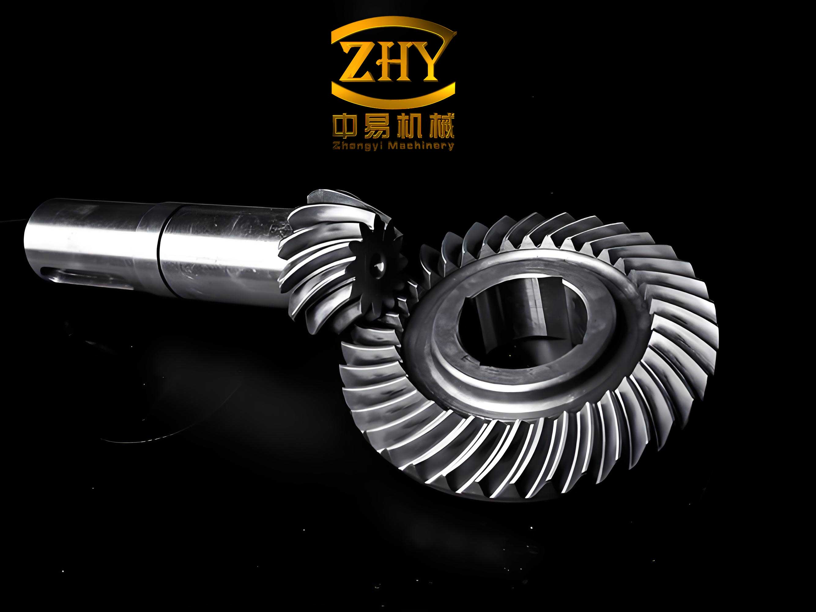
Fundamental Flaw in Traditional Generating Method: Origin of Diagonal Contact
To appreciate the innovation of the new method, one must first understand the root cause of diagonal contact in the traditional process. In the conventional generating method for machining spiral bevel gear pairs, the cutter head axis is typically installed perpendicular to the root cone of the gear being cut. This alignment is chosen to facilitate the simultaneous generation of the tooth flank and the root fillet. However, this setup introduces a fundamental discrepancy in the pressure angles along the tooth length.
Let’s analyze the geometry for the pinion. When the cutter axis is perpendicular to the pinion’s root cone, the pressure angles on the pitch line differ from the nominal cutter pressure angle. For a point at the mid-face width, the effective pressure angles on the convex (inner cutter) and concave (outer cutter) flanks are given by:
$$ \alpha_{i1} = \alpha – \Delta\alpha_1 $$
$$ \alpha_{a1} = \alpha + \Delta\alpha_1 $$
where \( \alpha \) is the nominal cutter pressure angle and \( \Delta\alpha_1 \) is a small correction angle. For small angles, this correction can be approximated as:
$$ \Delta\alpha_1 \approx \theta_{f1} \sin \beta $$
Here, \( \theta_{f1} \) is the pinion root angle and \( \beta \) is the spiral angle at the mid-point.
Similarly, for the gear (or wheel) machined with its cutter axis perpendicular to its own root cone, we have:
$$ \alpha_{i2} = \alpha – \Delta\alpha_2 $$
$$ \alpha_{a2} = \alpha + \Delta\alpha_2 $$
$$ \Delta\alpha_2 \approx \theta_{f2} \sin \beta $$
where \( \theta_{f2} \) is the gear root angle. The cutter “hook” or pressure angle modification is employed to ensure that at the midpoint of the pitch line, the mating pressure angles are equal (\( \alpha_{i1} = \alpha_{a2} \) and \( \alpha_{a1} = \alpha_{i2} \)) for proper conjugation.
The critical issue arises when we consider a point \( M_x \) located at a distance \( x \) from the mid-point along the tooth length. At this point, the local spiral angle \( \beta_x \) is different from \( \beta \). For a standard curved tooth, \( \beta_x \) increases from the toe to the heel. The local pressure angles at this point become:
For the pinion convex flank: \( \alpha_{i1x} = \alpha – \Delta\alpha_{1x} \), with \( \Delta\alpha_{1x} = \theta_{f1} \sin \beta_x \).
For the gear concave flank: \( \alpha_{a2x} = \alpha + \Delta\alpha_{2x} \), with \( \Delta\alpha_{2x} = \theta_{f2} \sin \beta_x \).
Since \( \beta_x > \beta \), it follows that \( \Delta\alpha_{1x} > \Delta\alpha_1 \) and \( \Delta\alpha_{2x} > \Delta\alpha_2 \). Consequently, \( \alpha_{i1x} < \alpha_{i1} \) and \( \alpha_{a2x} > \alpha_{a2} \). The equality of pressure angles (\( \alpha_{i1} = \alpha_{a2} \)) achieved at the mid-point no longer holds at other points along the tooth. The mismatch increases with \( |x| \). This systematic variation causes the point of contact to shift from the root at the heel to the tip at the toe, manifesting as the characteristic diagonal contact pattern. The following table summarizes this pressure angle mismatch.
| Component | Flank | Pressure Angle at Mid-point (\( \beta \)) | Pressure Angle at Point \( M_x \) (\( \beta_x > \beta \)) | Trend |
|---|---|---|---|---|
| Pinion | Convex (i1) | \( \alpha_{i1} = \alpha – \theta_{f1}\sin\beta \) | \( \alpha_{i1x} = \alpha – \theta_{f1}\sin\beta_x \) | Decreases |
| Gear | Concave (a2) | \( \alpha_{a2} = \alpha + \theta_{f2}\sin\beta \) | \( \alpha_{a2x} = \alpha + \theta_{f2}\sin\beta_x \) | Increases |
The Spread-Out Helix Modified Roll: Principle and Geometric Model
The proposed Spread-Out Helix Modified Roll method offers an elegant solution to this problem by fundamentally altering the cutter installation for the pinion. In this method:
- The gear (or wheel) is still machined using the standard generating method, with its cutter axis perpendicular to its root cone.
- The pinion is machined using a “Helix Modified Roll” process, where the cutter axis is installed perpendicular to the pinion’s face cone, not its root cone.
This strategic change aims to make the pressure angle variation on the pinion complementary to that on the gear, thereby achieving congruence along the entire tooth length.
Let’s derive the geometry for the pinion cutter installed perpendicular to the face cone. In this configuration, the effective pressure angles on the pitch line at the mid-face point become:
$$ \alpha_{i1}’ = \alpha + \Delta\alpha_1′ $$
$$ \alpha_{a1}’ = \alpha – \Delta\alpha_1′ $$
The correction term \( \Delta\alpha_1′ \) is now related to the pinion face angle (\( \theta_{a1} \)):
$$ \Delta\alpha_1′ \approx \theta_{a1} \sin \beta $$
For a standard spiral bevel gear pair, the face angle of the pinion is equal to the root angle of the gear (\( \theta_{a1} = \theta_{f2} \)). Similarly, the root angle of the pinion equals the face angle of the gear (\( \theta_{f1} = \theta_{a2} \)). This is a key relational property.
Therefore, comparing the pressure angles for the mating flanks at the mid-point:
- Pinion Convex (\( \alpha_{i1}’ \)) vs. Gear Concave (\( \alpha_{a2} \)):
$$ \alpha_{i1}’ = \alpha + \theta_{a1}\sin\beta = \alpha + \theta_{f2}\sin\beta $$
$$ \alpha_{a2} = \alpha + \theta_{f2}\sin\beta $$
$$ \Rightarrow \alpha_{i1}’ = \alpha_{a2} $$ - Pinion Concave (\( \alpha_{a1}’ \)) vs. Gear Convex (\( \alpha_{i2} \)):
$$ \alpha_{a1}’ = \alpha – \theta_{a1}\sin\beta = \alpha – \theta_{f2}\sin\beta $$
$$ \alpha_{i2} = \alpha – \theta_{f2}\sin\beta $$
$$ \Rightarrow \alpha_{a1}’ = \alpha_{i2} $$
Perfect equality is achieved at the mid-point, just as in the traditional method with hook correction.
The revolutionary advantage appears when we examine an arbitrary point \( M_x \). The local pressure angles become:
For the pinion convex flank: \( \alpha_{i1x}’ = \alpha + \theta_{a1} \sin \beta_x \).
For the gear concave flank: \( \alpha_{a2x} = \alpha + \theta_{f2} \sin \beta_x \).
Since \( \theta_{a1} = \theta_{f2} \), it follows that \( \alpha_{i1x}’ = \alpha_{a2x} \) for all points along the tooth length. The same holds true for the concave pinion/convex gear pair. The pressure angle mismatch that caused the diagonal contact is completely eliminated in theory. The comparison is summarized below:
| Method | Pinion Cutter Axis | Gear Cutter Axis | Condition at Point \( M_x \) | Result |
|---|---|---|---|---|
| Traditional Generating | Perpendicular to Root Cone | Perpendicular to Root Cone | \( \alpha_{i1x} \ne \alpha_{a2x} \) | Bias (Diagonal) Contact |
| Spread-Out Helix Modified Roll | Perpendicular to Face Cone | Perpendicular to Root Cone | \( \alpha_{i1x}’ = \alpha_{a2x} \) | Theoretically No Bias Contact |
Mathematical Modeling of Tooth Surface Generation
To analyze the meshing performance quantitatively, a precise mathematical model of the tooth surfaces generated by the Spread-Out Helix Modified Roll method is essential. The generation process for the pinion involves a helical motion of the cutter.
1. Cutter Surface Equation
For the pinion, the cutting surface is an Archimedean helicoid. Defining a coordinate system \( S_b \) attached to the cutter blade, a point \( P \) on the blade is given by \( \mathbf{r}_{b1}(u_1) \), where \( u_1 \) is a blade length parameter. Transforming to the cutter head coordinate system \( S_d \) which rotates with angle \( \theta_1 \), the point becomes \( \mathbf{r}_{d1}(u_1, \theta_1) \). Incorporating the helical feed motion with parameter \( p \), the equation of the cutter surface in \( S_d \) is:
$$
\mathbf{r}_{d1}(u_1, \theta_1) =
\begin{bmatrix}
(r_{c1} \pm \frac{W_1}{2} + u_1 \sin\alpha) \sin\theta_1 \\
(r_{c1} \pm \frac{W_1}{2} + u_1 \sin\alpha) \cos\theta_1 \\
-u_1 \cos\alpha + p\theta_1
\end{bmatrix}
$$
where \( r_{c1} \) is the cutter point radius, \( W_1 \) is the point width, \( \alpha \) is the pressure angle, and the \( \pm \) sign corresponds to the outer and inner blades, respectively. For the gear machured by the standard generating method, the helical parameter \( p = 0 \).
2. Machine Kinematics and Generation of Crown Gear
The cutter head is mounted on a machine cradle. The coordinate transformation from the cutter head system \( S_d \) to the fixed machine system \( S_m \) involves the radial setting \( s \), the basic cradle angle \( q \), and the cradle rotation angle \( \phi_1 \). The surface of the imaginary crown gear (generating gear) in the machine system is:
$$ \mathbf{r}_{m1}(u_1, \theta_1, \phi_1) = \mathbf{M}_{mc}(\phi_1) \mathbf{M}_{cd}(s, q) \mathbf{r}_{d1}(u_1, \theta_1) $$
3. Workpiece Setup and Pinion Tooth Surface Equation
The workpiece (pinion) is positioned relative to the machine via several setup parameters: the sliding base setting \( X_{B1} \), the machine root angle \( \delta_{a1} \), the blank offset \( X_1 \), and the work rotation angle \( \psi_1 \). The crown gear surface \( \mathbf{r}_{m1} \) must be conjugate to the pinion tooth surface. Applying the coordinate transformation from \( S_m \) to the workpiece system \( S_{w1} \) and enforcing the equation of meshing yields the pinion tooth surface:
$$ \mathbf{r}_{w1}(u_1, \theta_1, \phi_1) = \mathbf{M}_{w1m}(\psi_1, X_1, \delta_{a1}, X_{B1}) \mathbf{r}_{m1}(u_1, \theta_1, \phi_1) $$
$$ f_1(u_1, \theta_1, \phi_1) = \mathbf{n}_{w1} \cdot \mathbf{v}_{w1}^{(12)} = 0 $$
where \( \mathbf{n}_{w1} \) is the unit normal to the surface and \( \mathbf{v}_{w1}^{(12)} \) is the relative velocity between the crown gear and the pinion. The simultaneous solution of the surface equation and the equation of meshing defines the pinion tooth surface as a function of two independent parameters: \( \mathbf{r}_1(\phi_1, \theta_1) \). A similar, but simpler, model (with \( p=0 \)) is applied for the gear tooth surface \( \mathbf{r}_2(\phi_2, \theta_2) \).
Tooth Contact Analysis (TCA) and Comparative Results
Tooth Contact Analysis is performed by simulating the meshing of the theoretically generated pinion and gear surfaces in their assembled position. The TCA fundamental equations require that at any contact point, the position vectors and the unit normals of both surfaces coincide in a fixed coordinate system \( S_a \):
$$ \mathbf{r}_{a1}(\phi_1, \theta_1, \varphi_1) – \mathbf{r}_{a2}(\phi_2, \theta_2, \varphi_2) = \mathbf{O}_1\mathbf{O}_2 $$
$$ \mathbf{n}_{a1}(\phi_1, \theta_1, \varphi_1) – \mathbf{n}_{a2}(\phi_2, \theta_2, \varphi_2) = 0 $$
where \( \varphi_1 \) and \( \varphi_2 \) are the rotation angles of the pinion and gear, respectively. This system of vector equations provides five independent scalar equations. With six unknowns (\( \phi_1, \theta_1, \varphi_1, \phi_2, \theta_2, \varphi_2 \)), one parameter (e.g., \( \varphi_2 \)) can be taken as input. Solving the system yields the contact path on the tooth flank and the transmission error \( \Delta \varphi_1(\varphi_2) \).
A spiral bevel gear pair was analyzed using both the traditional generating method and the proposed Spread-Out Helix Modified Roll method. The basic blank and machine settings are shown below:
| Parameter | Pinion (Left-Hand, Concave Flank Analyzed) | Gear (Right-Hand, Convex Flank Analyzed) |
|---|---|---|
| Shaft Angle \( \Sigma \) | 90° | 90° |
| Number of Teeth \( z \) | 11 | 34 |
| Module at Ref. Point \( m_n \) | 6.5 mm | 6.5 mm |
| Spiral Angle \( \beta \) | 35° | 35° |
| Face Width \( B \) | 35 mm | 35 mm |
The results of the TCA are conclusive. The table below lists the coordinates of contact points along the path for both methods, where \( x \) is the direction along the tooth length (heel to toe) and \( y \) is the direction along the tooth profile (root to tip).
| Contact Pt. | Traditional Generating Method | Spread-Out Helix Modified Roll | ||
|---|---|---|---|---|
| # | \( x \) (mm) | \( y \) (mm) | \( x \) (mm) | \( y \) (mm) |
| 1 | -2.5515 | 3.0754 | -2.1557 | 3.3097 |
| 2 | -1.8187 | 3.3571 | -1.0181 | 3.7263 |
| 3 | -0.8406 | 4.5483 | -0.5148 | 4.4160 |
| 4 | 0.0000 | 5.1193 | 0.0000 | 5.1193 |
| 5 | -0.8021 | 5.8878 | -0.3301 | 5.8716 |
| 6 | -1.7935 | 6.7065 | -0.5088 | 6.6962 |
| 7 | -2.4231 | 7.6477 | -0.6809 | 7.6787 |
| Spread (Range) | 4.9746 mm | 4.5723 mm | 2.8366 mm | 4.3690 mm |
The key observation is the spread in the \( x \)-direction. For the traditional method, the contact path spans nearly 5.0 mm along the face width, indicating a pronounced diagonal orientation. In contrast, the contact path for the Spread-Out Helix Modified Roll method spans only about 2.8 mm, demonstrating a significantly more upright, nearly lengthwise contact pattern. The spread in the \( y \)-direction (profile direction) is similar for both, indicating comparable contact height.
The transmission error curves further validate the improvement. The curve for the new method exhibits a lower amplitude and a smoother, more symmetric shape without crossings that might indicate edge contact, suggesting a more favorable and stable meshing condition under light load compared to the traditional method.
Verification Through Machining and Testing
Theoretical analysis was substantiated by practical machining and testing. A gear pair was cut on a modern CNC spiral bevel gear generator programmed with the machine settings derived for the Spread-Out Helix Modified Roll method. The manufactured gear pair was then subjected to a rolling test on a gear testing machine. The observed contact pattern on the gear convex flank confirmed the TCA predictions: the contact zone was well-centered, regular in shape, and exhibited no discernible diagonal bias. This practical result provides strong evidence for the efficacy of the proposed method in producing high-quality spiral bevel gear meshing characteristics.
Conclusion
In this comprehensive analysis, I have presented the Spread-Out Helix Modified Roll as a novel and effective machining method for spiral bevel gears. By installing the pinion cutter perpendicular to the face cone instead of the root cone, the inherent pressure angle mismatch along the tooth length—the root cause of diagonal contact in traditional generating methods—is fundamentally corrected. Detailed geometric modeling confirms the theoretical elimination of bias contact. Mathematical modeling of the tooth surface generation, incorporating the helical motion for the pinion, provides the foundation for precise Tooth Contact Analysis. Comparative TCA results between the traditional and the new method clearly demonstrate the superior contact pattern achieved by the Spread-Out Helix Modified Roll: a more upright, centralized contact path and improved transmission error characteristics. Finally, successful machining and rolling tests on an actual gear pair provide practical validation. This method therefore represents a significant step forward in the manufacturing of high-performance spiral bevel gear drives, offering a direct solution to a long-standing meshing quality issue.