
The accurate prediction of instantaneous maximum surface temperature is a cornerstone in the design of high-performance gear transmissions, particularly for applications where reliability under extreme conditions is non-negotiable. Among various gear types, spiral bevel gears are prized for their efficiency and smooth power transmission in complex drive systems, such as helicopter main gearboxes. A critical failure mode for these components is scuffing, a severe adhesive wear mechanism directly linked to excessive localized temperature rise at the contacting tooth surfaces. The classical approach for assessing this risk is the Blok flash temperature method, which estimates the transient temperature spike at the point of contact. However, its foundational model assumes direct metallic contact, neglecting the critical thermal influence of the lubricant film invariably present in enclosed gearboxes. This paper presents a first-person account of the development and application of an enhanced flash temperature calculation method. By rigorously integrating the thermal behavior of the elastohydrodynamic lubrication (EHL) film into the classical framework, we derive a more physically accurate formula for predicting surface flash temperature in lubricated spiral bevel gears.
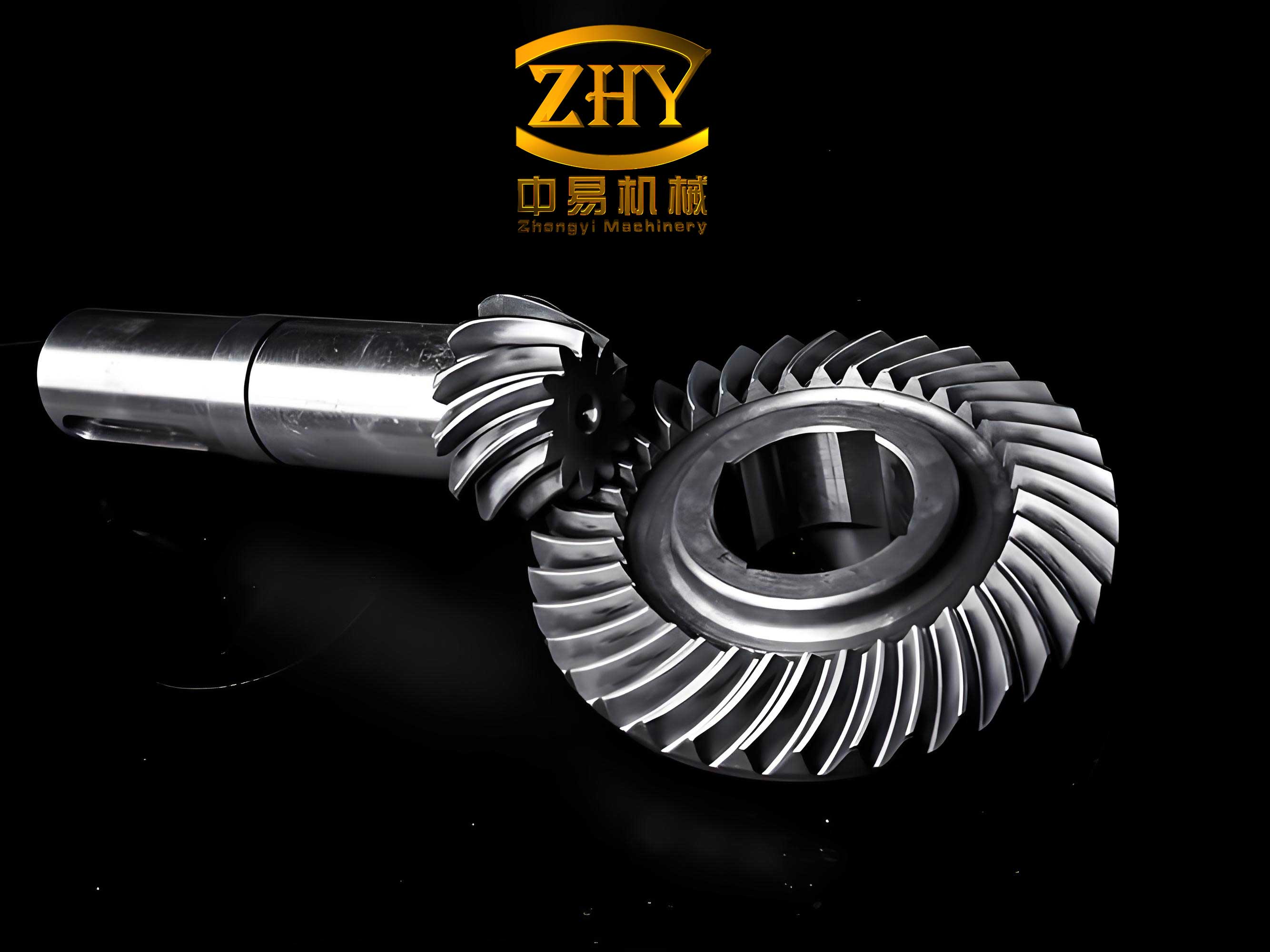
The operational demands on spiral bevel gears are immense. They transmit significant power at high rotational speeds, subjecting the contacting surfaces to intense pressures and sliding velocities. The resulting friction within the contact conjunction generates heat. While the presence of a lubricant film is essential for separating surfaces and reducing friction, the shearing of this very film under high pressure becomes a primary heat source. The traditional Blok method, formulated for dry contact, partitions this frictional heat directly between the two gear bodies based on their thermal properties and velocities. In reality, for a lubricated spiral bevel gear pair, the heat is first generated within the oil film. A portion of this heat is conducted into the contacting surfaces, raising their temperature, while another portion may be carried away by the lubricant itself. Ignoring this layer leads to an incomplete thermal model. Therefore, our objective was to refine the Blok formulation by considering the lubricant as a distinct, thin conductive layer, thereby developing a flash temperature prediction tool specifically suited for the EHL conditions typical of spiral bevel gear operation.
1. Foundation and Limitations of the Classical Blok Method
The classical Blok flash temperature model considers two semi-infinite bodies (gear teeth) sliding against each other with a constant heat flux $q_t$ generated over a rectangular contact band of width $l$. The core equations provide the temperature rise above the bulk temperature $t_b$ for each surface:
$$
t_{s1} – t_{b1} = \frac{1.11 \phi q_t}{\sqrt{\lambda_1 \rho_1 c_1 V_1 l}}
$$
$$
t_{s2} – t_{b2} = \frac{1.11 (1-\phi) q_t}{\sqrt{\lambda_2 \rho_2 c_2 V_2 l}}
$$
Here, subscripts 1 and 2 denote the driving and driven gears, respectively. $t_s$ is the instantaneous surface temperature (flash temperature), $\lambda$ is thermal conductivity, $\rho$ is density, $c$ is specific heat capacity, and $V$ is the tangential velocity at the contact point. The heat partition coefficient $\phi$ determines the fraction of the total frictional heat $q_t$ entering the first body. The critical, and limiting, assumption of the Blok method is that the surfaces are in perfect contact and thus attain the same flash temperature ($t_{s1} = t_{s2}$). Solving for $\phi$ under this condition yields:
$$
\phi = \frac{1}{1 + \sqrt{\dfrac{\lambda_2 \rho_2 c_2 V_2}{\lambda_1 \rho_1 c_1 V_1}}}
$$
This formula, while elegant, is fundamentally designed for dry or boundary lubrication scenarios. For spiral bevel gears operating in the mixed or full-film EHL regime, this model is inadequate as it completely bypasses the thermal dynamics of the lubricant film. Practical applications often apply empirical correction factors, but these lack a solid physical basis.
2. Development of the Improved Blok Flash Temperature Method
Our improved method conceptualizes the contact of a lubricated spiral bevel gear pair as a three-layer system: the driving gear body, a central lubricant film, and the driven gear body. The total film thickness is $h$. The frictional heat $q_t$ is generated within the shearing lubricant film. The heat partition is now a two-stage process: first, the heat is partitioned between the two halves of the oil film adhering to each surface, and subsequently, the heat from each oil film layer is conducted into the respective gear tooth.
2.1 Thermal Model for Layered Bodies
The work of Rashid and Seireg on transient heat conduction in layered solids provides the foundational relationships. For a moving heat source over a two-layer body, they derived dimensionless expressions for the temperature difference across the layers. Adapting this to our gear model, we treat the oil film as the first layer and the gear metal as the second. For the driving gear side, the temperature difference between the oil-film interface ($t_{o1}$) and the dry-contact equivalent surface temperature ($t_{s1}$) is given by:
$$
t_{o1} – t_{s1} = \phi q_t B_1
$$
where $B_1$ is a comprehensive coefficient encapsulating the thermal and kinematic properties of the oil and the gear material, as well as the contact geometry. A similar equation holds for the driven gear side with coefficient $B_2$. Crucially, we abandon the assumption of equal surface temperatures. Instead, we assert that within the very thin lubricant film, the temperature can be considered uniform across its thickness at the contact point, leading to:
$$
t_{o1} = t_{o2}
$$
This condition allows us to solve for a new, first-stage heat partition coefficient $\phi$ that accounts for the oil film and the bulk temperature difference between the two spiral bevel gears:
$$
\phi = \frac{1}{A_1 + B_1 + A_2 + B_2} \cdot \left( \frac{t_{b2} – t_{b1}}{q_t} + A_2 + B_2 \right)
$$
Here, $A_1$ and $A_2$ are the classical Blok coefficients ($A_1 = 1.11 / \sqrt{\lambda_1 \rho_1 c_1 V_1 l}$). Next, we relate the dry-contact surface temperature $t_s$ to the actual, lubricated surface temperature $t_{so}$ using the second Rashid and Seireg relationship, introducing coefficients $C_1$ and $C_2$:
$$
t_{s1} – t_{so1} = \phi q_t C_1
$$
$$
t_{s2} – t_{so2} = (1-\phi) q_t C_2
$$
2.2 The Improved Flash Temperature Formula
By combining the modified Blok equations (linking $t_s$ to $t_b$) with the layer-correction equations (linking $t_s$ to $t_{so}$), we eliminate the intermediate variable $t_s$. This yields the final improved flash temperature formulas for the lubricated spiral bevel gear contact:
$$
t_{so1} – t_{b1} = \phi q_t (A_1 – C_1)
$$
$$
t_{so2} – t_{b2} = (1-\phi) q_t (A_2 – C_2)
$$
This result can be elegantly reformatted to resemble the structure of the original Blok equation by defining new, effective heat partition coefficients $\gamma_1$ and $\gamma_2$ that represent the net fraction of the total friction heat $q_t$ that actually enters each gear body after accounting for losses/storage in the oil film:
$$
\gamma_1 = \phi \frac{A_1 – C_1}{A_1}, \quad \gamma_2 = (1-\phi) \frac{A_2 – C_2}{A_2}
$$
$$
\boxed{t_{so1} – t_{b1} = \gamma_1 q_t A_1}
$$
$$
\boxed{t_{so2} – t_{b2} = \gamma_2 q_t A_2}
$$
These coefficients $\gamma_1$ and $\gamma_2$ are functions of the thermal properties of both gears and the lubricant, the oil film thickness $h$, the bulk temperatures, and the operating kinematics, providing a far more comprehensive model than the original Blok coefficient $\phi$.
3. Alternative and Validation Methods
3.1 Joselito’s Flash Temperature Method
As a point of comparison, we consider the method proposed by Joselito, which also aims to predict flash temperature under lubricated conditions. It presents a semi-empirical formula derived from numerical simulations:
$$
t_{so1} – t_{b1} = \frac{q_t D_1}{\lambda_o}, \quad t_{so2} – t_{b2} = \frac{q_t D_2}{\lambda_o}
$$
where $D_1$ and $D_2$ are complex dimensionless groups involving exponential and power-law functions of the relevant thermal and kinematic parameters, including the bulk temperature difference and the lubricant’s properties. This method will serve as a benchmark against our improved Blok method.
3.2 Finite Element Analysis (FEA) Methodology
To establish a reference solution, a detailed 3D transient thermal finite element analysis is employed. Given the cyclic and symmetric nature of gear meshing, a single-tooth model for each spiral bevel gear is sufficient. The process involves two sequential simulations:
- Steady-State Analysis: Determines the bulk temperature field $t_b$ by applying the average heat generation rate over a mesh cycle to the contacting tooth flank, along with convective boundary conditions on all tooth surfaces.
- Transient Analysis: Uses the steady-state result as the initial condition. The instantaneous heat flux is then applied to the contact path for a duration equal to one mesh cycle, simulating the flash heating event. The resulting peak temperature minus the local bulk temperature gives the FEA-calculated flash temperature.
The convective heat transfer coefficients ($\alpha$) for different tooth regions are calculated using established empirical formulas for rotating bodies and gears. The key formulas are summarized below:
| Surface Region | Heat Transfer Coefficient Formula | Parameters |
|---|---|---|
| Meshing Flank | $\alpha = 0.228 \cdot Re \cdot Pr \cdot \lambda_o / L$ | $Re$: Reynolds number, $Pr$: Prandtl number, $L$: Characteristic length (e.g., pitch diameter). |
| Gear End Face (Laminar) | $\alpha_{lf} = 0.308 (m+2)^{0.5} Pr^{0.5} \lambda_o (\omega / \nu)^{0.5}$ | $\omega$: Angular speed, $\nu$: Kinematic viscosity, $m$: Temperature profile exponent (taken as 2). |
| Gear End Face (Turbulent) | $\alpha_{tf} = 0.0197 (m+2.6)^{0.2} Pr^{0.6} \lambda_o (\omega / \nu)^{0.8} x^{0.6}$ | $x$: Radial distance from center. |
| Non-working Surfaces | $\alpha_{nw} \approx (1/3 \text{ to } 1/2) \cdot \bar{\alpha}_{face}$ | $\bar{\alpha}_{face}$ is the average coefficient of the end face. |
4. Numerical Application to a Helicopter Spiral Bevel Gear Pair
To demonstrate and validate the improved method, we apply it to a spiral bevel gear pair from a helicopter transmission. The primary parameters are listed in the table below.
| Parameter | Value (Pinion/Gear) | Parameter | Value |
|---|---|---|---|
| Number of Teeth | 27 / 74 | Gear Density | 7850 kg/m³ |
| Module | 3.85 mm | Gear Conductivity | 36 W/(m·°C) |
| Face Width | 38.5 mm | Gear Specific Heat | 641 J/(kg·°C) |
| Input Speed | 20900 rpm | Oil Density | 970.2 kg/m³ |
| Input Power | 1000 kW | Oil Conductivity | 0.147 W/(m·°C) |
| Spiral Angle | 35° | Oil Specific Heat | 2131 J/(kg·°C) |
4.1 Kinematic and Thermal Load Calculation
The analysis is focused on the mean point of the tooth flank. The complex motion of the spiral bevel gear is simplified using the equivalent spur gear methodology. The tangential velocities $V_1$ and $V_2$, sliding velocity $V_s$, and entrainment velocity $V_r$ at any contact point are derived geometrically:
$$
V_1 = |N_1C|\omega_1, \quad V_2 = |N_2C|\omega_2
$$
$$
V_s = |V_1 – V_2|, \quad V_r = (V_1 + V_2)/2
$$
The unit frictional heat generation is calculated as:
$$
q_t = f \cdot P_c \cdot V_s
$$
where $f$ is the friction coefficient and $P_c$ is the Hertzian contact pressure. The heat fluxes used in the FEA, $Q_1$ and $Q_2$, are the time-averaged values of $\gamma_1 q_t$ and $\gamma_2 q_t$ over a single mesh cycle.
4.2 Results and Comparative Analysis
The finite element simulation provides the baseline bulk and flash temperatures. The improved Blok method and Joselito’s method are then used to calculate the flash temperature at the mean point under the 1000 kW load condition. The results are compared in the following table.
| Method | Bulk Temp., $t_b$ (°C) | Flash Temp. Rise (°C) | Peak Surface Temp. (°C) |
|---|---|---|---|
| Finite Element (Reference) | 75.36 / 72.03 | 15.28 / 19.56 | 90.64 / 91.59 |
| Improved Blok Method | 75.36 / 72.03 | 19.11 / 18.41 | 94.47 / 90.44 |
| Joselito’s Method | 75.36 / 72.03 | 26.62 / 27.97 | 101.98 / 100.00 |
The key metric for scuffing risk assessment is the peak surface temperature. Comparing to the FEA reference, the Improved Blok Method shows a deviation of approximately 4% for the driving spiral bevel gear (94.47°C vs. 90.64°C) and 1.2% for the driven gear. In contrast, Joselito’s Method deviates by about 12.5% and 9.2%, respectively. This demonstrates the superior accuracy of the proposed improved method for this spiral bevel gear application.
4.3 Parametric Studies and Method Robustness
To further evaluate the robustness and physical consistency of the improved Blok method, parametric studies were conducted.
Effect of Input Power: The input power was varied from 800 kW to 1200 kW. As expected, all three methods predict an increase in flash temperature with power. Crucially, the improved Blok method consistently tracks closer to the FEA trend line than Joselito’s method across the power range, confirming its stability.
Effect of Lubricant Properties: Different lubricant types (with varied density $\rho_o$, conductivity $\lambda_o$, and specific heat $c_o$) were tested. The improved method correctly reflects the influence of these properties. Analysis shows that flash temperature is inversely proportional to $\rho_o$ and $c_o$, and directly proportional to $\lambda_o$. The influence of density and specific heat is more pronounced than that of conductivity, which aligns with their mathematical relationship in the model’s coefficients. This logical behavior further validates the physical soundness of the derived formulas for spiral bevel gear analysis.
5. Conclusions
This work has successfully developed and validated an improved methodology for calculating the flash temperature in lubricated spiral bevel gear contacts. The principal conclusions are as follows:
- Enhanced Physical Model: The improved Blok method overcomes a fundamental limitation of the classical approach by explicitly modeling the lubricant film as a conductive thermal layer. This yields a more realistic two-stage heat partition process between the oil film and the gear bodies.
- Superior Accuracy for Spiral Bevel Gears: When applied to a high-performance helicopter spiral bevel gear pair, the improved method predicted peak surface temperatures within ~4% of detailed 3D transient FEA results. This accuracy was notably better than an alternative established method (Joselito’s), which showed ~12% deviation.
- Robust and Physically Consistent: The method demonstrated stable and predictable behavior across a range of operating powers and with different lubricant properties. The calculated sensitivity of flash temperature to lubricant density, specific heat, and conductivity follows logical and mathematically consistent trends, reinforcing the model’s validity.
- Practical Utility: The final formulas maintain a structure similar to the well-known Blok equation but incorporate the crucial corrections via the effective heat partition coefficients $\gamma_1$ and $\gamma_2$. This provides a relatively straightforward yet significantly more accurate tool for engineers to assess the scuffing risk in critical spiral bevel gear applications during the design phase.
This improved flash temperature methodology offers a stronger theoretical foundation for the thermal aspect of spiral bevel gear scuffing load capacity calculation, contributing to the design of more reliable and durable aerospace and automotive transmissions.