
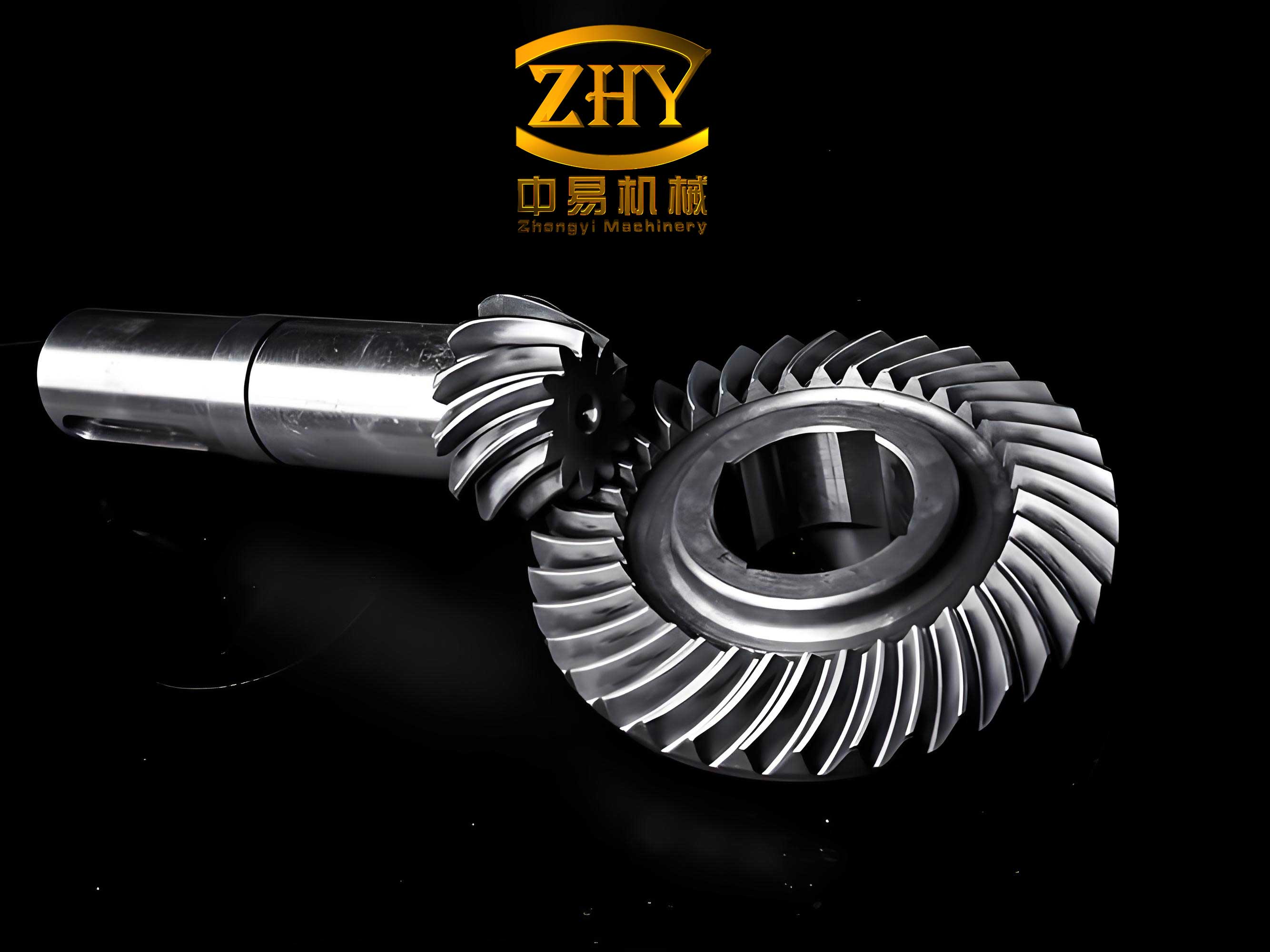
In my experience with power transmission systems for heavy machinery, the spiral bevel gear stands out as one of the most critical and demanding components. Its performance directly dictates the operational smoothness, noise levels, and ultimately, the service life of the entire gearbox and the machine it drives. The single most important indicator of a spiral bevel gear pair’s quality is the contact pattern—the area where the teeth of the pinion and the gear actually meet under load. The position, size, and shape of this pattern are paramount. An incorrect pattern leads to premature wear, increased noise, and potential catastrophic failure. Therefore, the ability to interpret the pattern’s behavior on a testing machine and systematically correct it through precise machine adjustments is an essential skill in gear manufacturing.
The foundation of effective spiral bevel gear contact correction lies in understanding the predictable shifts that occur when the relative positioning of the mating gears is altered on a gear rolling tester. By deliberately moving the tester’s head (which holds one gear) vertically (V) or horizontally (H), we can map how the pattern migrates across the tooth face. This diagnostic step tells us the nature of the error.
For a right-hand spiral gear (typically the larger gear), the contact pattern movement follows the rules summarized below. A vertical displacement changes the effective mounting distance, primarily affecting the pattern along the profile (toe-heel direction), while a horizontal displacement acts like a change in axial alignment, shifting the pattern across the face width (flank direction).
| Roll Tester Head Movement Direction | Contact Pattern Movement Direction on Tooth Flank | Primary Pattern Shift |
|---|---|---|
| Vertical Up (V+) | Towards Toe | Along Face Width |
| Vertical Down (V-) | Towards Heel | Along Face Width |
| Horizontal In (H+) | Towards Top (Root on concave, Top on convex) | Along Profile |
| Horizontal Out (H-) | Towards Root (Top on concave, Root on convex) | Along Profile |
Conversely, for the left-hand spiral pinion, the pattern reacts differently to the same machine movements. These inverse relationships are crucial for diagnosis because during testing, we observe the combined effect of both gears’ errors on the pattern position.
| Roll Tester Head Movement Direction | Contact Pattern Movement Direction on Tooth Flank | Primary Pattern Shift |
|---|---|---|
| Vertical Up (V+) | Towards Heel | Along Face Width |
| Vertical Down (V-) | Towards Toe | Along Face Width |
| Horizontal In (H+) | Towards Root (Top on concave, Root on convex) | Along Profile |
| Horizontal Out (H-) | Towards Top (Root on concave, Top on convex) | Along Profile |
Once the error is diagnosed, correction is applied almost exclusively by re-cutting the pinion. This is a practical choice due to the pinion’s fewer teeth and shorter machining time. The goal is to modify the pinion’s tooth geometry to achieve a centered, properly sized contact pattern under nominal assembly conditions. The corrections target specific geometric parameters: spiral angle, pressure angle, and tooth curvature.
Correcting Contact Pattern along the Face Width (Toe-Heel Direction)
A pattern biased towards the toe or heel of the tooth indicates an error in the spiral angle at the pitch cone. This is corrected by adjusting the cutter head’s radial setting, known as the “cutter radius” or “tilt angle” on some machines. Adjusting this setting changes the nominal spiral angle generated on the workpiece. The relationship between cutter radial position $$ R_c $$ and the mean spiral angle $$ \beta_m $$ can be approximated for setup purposes. A change in the spiral angle $$\Delta \beta$$ requires a corresponding change in cutter radius $$\Delta R_c$$:
$$\Delta R_c \approx k_1 \cdot \Delta \beta$$
where $$k_1$$ is a machine and gear geometry-dependent constant. The effect of this adjustment is consistent.
| Pattern Condition on Pinion | Required Adjustment |
|---|---|
| Pattern too far towards Toe | Increase Cutter Radius (or Tilt Angle) |
| Pattern too far towards Heel | Decrease Cutter Radius (or Tilt Angle) |
Typical adjustment increments are in the range of 1-3 mm for the cutter radius setting.
Correcting Contact Pattern along the Profile (Root-Top Direction)
A pattern sitting too high (near the top) or too low (near the root) signifies a pressure angle error. The primary and most efficient method to correct this is by modifying the “horizontal wheel setting” or “sliding base” setting during cutting. This changes the effective pressure angle. When this setting is altered, the nominal spiral angle is also affected. Therefore, a compensating change to the cutter radius setting must be made simultaneously to maintain the correct spiral angle. If $$\Delta X$$ is the change in horizontal setting (positive for increasing mounting distance), the required compensating change in cutter radius $$\Delta R_{c,comp}$$ and the corresponding change in machine center $$\Delta \Delta$$ are governed by the machine’s kinematics. A simplified relationship is:
$$\Delta R_{c,comp} \approx k_2 \cdot \Delta X$$
and
$$\Delta \Delta \approx k_3 \cdot \Delta X$$
where $$k_2$$ and $$k_3$$ are constants derived from the machine’s basic settings.
| Pattern Condition on Pinion | Required Adjustment | Consequential Adjustment |
|---|---|---|
| Pattern too high (Top contact) | Decrease Horizontal Setting (Move in) | Decrease Cutter Radius, Increase Machine Center |
| Pattern too low (Root contact) | Increase Horizontal Setting (Move out) | Increase Cutter Radius, Decrease Machine Center |
For substantial pressure angle errors, adjusting the ratio of roll (gear generating ratio) is more effective. Changing the rolling gear ratio $$i_r$$ directly alters the curvature relationship between the generating gear and the workpiece, strongly influencing the pressure angle. The adjustment is often determined empirically or based on the amount of axial shift $$\Delta A$$ required on the rolling tester to center the pattern. The new ratio of roll $$i_{r,new}$$ can be found from:
$$i_{r,new} \approx i_{r,old} \cdot (1 + C \cdot \Delta A)$$
where C is an empirical factor. The direction of change is critical.
| Pattern Condition | Required Change in Ratio of Roll |
|---|---|
| Pattern too high on tooth | Increase Ratio of Roll |
| Pattern too low on tooth | Decrease Ratio of Roll |
Correcting Diagonal Contact Patterns
A diagonal contact pattern is a challenging condition where the pattern runs across the tooth face from, for example, the toe-top corner to the heel-root corner. This indicates a complex error involving a combination of spiral angle and pressure angle deviations that vary along the face width. It is categorized as “Inside Diagonal” or “Outside Diagonal”.
- Inside Diagonal: On the convex side, the pattern runs from Toe-Top to Heel-Root. On the concave side, it runs from Toe-Root to Heel-Top.
- Outside Diagonal: On the convex side, the pattern runs from Toe-Root to Heel-Top. On the concave side, it runs from Toe-Top to Heel-Root.
Correcting a diagonal pattern requires a coordinated change to two or more machine settings to introduce a compensating “twist” to the tooth surface. The standard approach is to adjust the ratio of roll and the horizontal wheel setting together, with corresponding changes to the cutter radius and machine center to maintain other parameters.
| Diagonal Type | Tooth Flank | Adjust Ratio of Roll | Adjust Horizontal Setting | Consequential Cutter Radius Change |
|---|---|---|---|---|
| Inside Diagonal | Concave | Increase | Decrease | Decrease |
| Convex | Decrease | Increase | Increase | |
| Outside Diagonal | Concave | Decrease | Increase | Increase |
| Convex | Increase | Decrease | Decrease |
Correcting Contact Pattern Length and Width
The physical size of the pattern is just as important as its location. A pattern that is too long (excessive face contact) can lead to edge loading under misalignment, while one that is too short reduces load-carrying capacity. Pattern length is primarily controlled by the radius of the generating cutter head, $$ R_{cut} $$. A larger cutter radius produces a longer pattern, and a smaller radius a shorter one. Changing the cutter radius requires a proportional change in the basic cutter radial setting $$ R_c $$ to maintain the nominal spiral angle. The relationship is approximately linear for small changes:
$$\Delta R_c \approx \Delta R_{cut}$$
The effect is uniform across both flanks.
| Pattern Condition | Required Cutter Radius Change | Required Cutter Setting Change |
|---|---|---|
| Pattern too long | Decrease $$ R_{cut} $$ | Decrease $$ R_c $$ |
| Pattern too short | Increase $$ R_{cut} $$ | Increase $$ R_c $$ |
The width of the contact pattern (along the profile direction) is adjusted via the “vertical wheel setting” or “offset” ($$E$$). This setting moves the workpiece radially relative to the cutter center, modifying the tooth depth and profile curvature. Increasing the offset generally narrows the pattern, while decreasing it widens the pattern. This adjustment also affects the pressure angle, so minor follow-up adjustments to the horizontal setting or ratio of roll may be needed for final tuning. A typical adjustment range is 1-5 mm.
| Pattern Condition | Required Vertical Offset ($$E$$) Adjustment |
|---|---|
| Pattern too wide | Increase Offset |
| Pattern too narrow | Decrease Offset |
The successful manufacturing of high-performance spiral bevel gears is a blend of precise science and refined art. It requires not only a deep theoretical understanding of gear geometry but also the practical expertise to interpret contact patterns and translate them into precise machine-tool adjustments. By systematically applying the principles of contact pattern diagnosis and correction—targeting spiral angle via cutter radius, pressure angle via horizontal setting or ratio of roll, and pattern size via cutter head radius and vertical offset—the quality and longevity of the gear pair are assured. Mastery of this process is fundamental to producing reliable and efficient power transmission systems, ensuring that the critical spiral bevel gear performs flawlessly throughout its service life.