
In the manufacturing of high-precision spiral bevel gears, hard finishing processes such as skiving are critical for achieving superior surface quality and dimensional accuracy. The skiving cutter with a plane flank, often referred to as a “尖齿刮削刀盘” in the referenced literature, presents unique challenges due to its straight-line cutting edge design with an inclined angle. This design, while simplifying fabrication, introduces significant profile generation errors and resharpening errors, which can degrade the quality of the finished spiral bevel gear. In this comprehensive analysis, I will delve into the methodologies for optimizing the tooth profile of such skiving cutters, focusing on minimizing these errors through parametric analysis and systematic design. The spiral bevel gear is a central component in many power transmission systems, and its manufacturing precision directly impacts performance and longevity. Therefore, refining the cutter design is paramount.
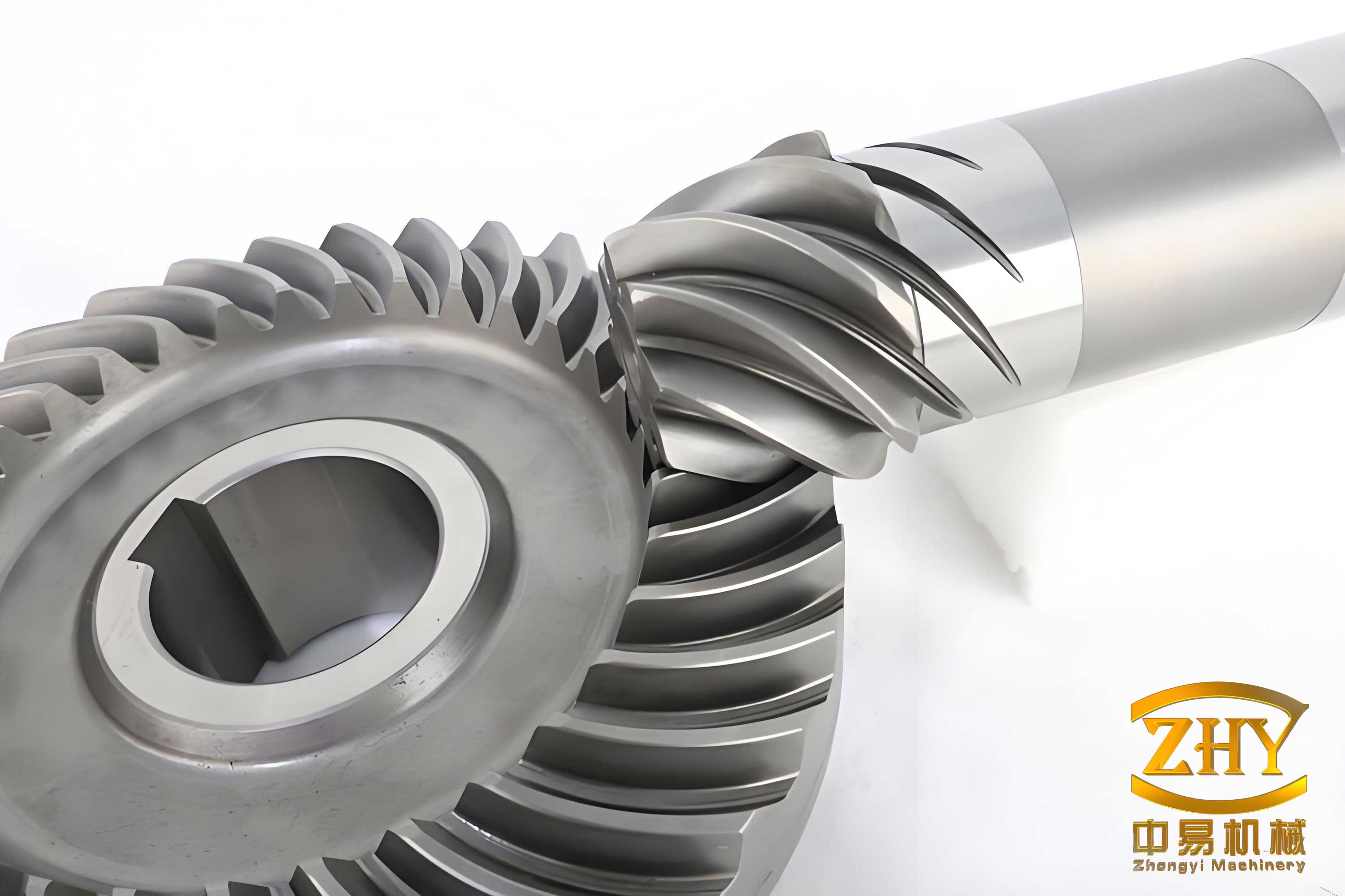
The skiving process for hard-faced spiral bevel gears employs a cutter whose cutting edge is generated using the “斜角直线造形法” or inclined straight-line profiling method. In this method, the cutter’s cutting edge is a straight line that is tangent to the generating conical surface of the roughing cutter (typically a spiral bevel gear milling cutter) at the midpoint of the gear tooth’s contact zone. While this approach facilitates cutter grinding, it inherently leads to deviations between the cutter’s axial profile and the ideal profile derived from the milling cutter. These deviations are defined as the profile generation error. For the outer blade of the skiving cutter, the error at any point K on the cutting edge can be expressed by the following equation, which incorporates key geometric parameters:
$$ \Delta f_e(H) = \left[ (h + e_e \tan \lambda_e)(H – h) \right] + \left[ (R_e^2 – (H \tan \alpha_{oe} + e_e)^2 + (H \tan \lambda_e \tan \alpha_{oe} + e_e \tan \lambda_e)^2 )^{1/2} – (R_e – H \tan \alpha_{oe}) \right] $$
Where:
$e_e$ is the tool tip offset for the outer blade,
$h$ is the distance from the tool tip to the reference xoy plane,
$H$ is the distance from point K on the cutting edge to the xoy plane,
$\lambda_e$ is the inclination angle of the outer blade,
$\alpha_{oe}$ is the original profile angle (nominal pressure angle),
$R_e$ is the rotational radius at the calculation base point $m_0$.
Similarly, for the inner blade, the profile generation error is given by:
$$ \Delta f_i(H) = \left[ (h + e_i \tan \lambda_i)(H – h) \right] + \left[ (R_i^2 – (H \tan \alpha_{oi} – e_i)^2 + (H \tan \lambda_i \tan \alpha_{oi} – e_i \tan \lambda_i)^2 )^{1/2} – (R_i + H \tan \alpha_{oi}) \right] $$
The parameters for the inner blade are denoted by the subscript $i$. Analysis of these equations reveals fundamental trends in the behavior of spiral bevel gear cutter errors. To summarize the influence of various parameters on the profile generation error, the following table is constructed:
| Parameter | Effect on Outer Blade Error | Effect on Inner Blade Error | Remarks |
|---|---|---|---|
| Tool Tip Offset ($e_e$, $e_i$) | Error decreases as $e_e$ increases. | Error increases as $e_i$ increases. | Opposite trends for inner and outer blades. |
| Inclination Angle ($|\lambda_e|$, $|\lambda_i|$) | Error increases as $|\lambda_e|$ increases. | Error increases as $|\lambda_i|$ increases. | Larger absolute inclination angles amplify errors for both. |
| Position along edge (from base point) | Error is zero at base point $m_0$ and increases towards tooth tip and root. | Error is zero at base point and increases towards tooth tip and root. | Error distribution is parabolic/symmetric around the contact midpoint. |
Beyond initial generation, the resharpening of the skiving cutter introduces another source of error, crucial for maintaining the accuracy of spiral bevel gears over the cutter’s lifespan. The recommended method is “compensation resharpening.” In this process, the worn cutting edge is reground along the flank face, and the cutter insert is axially adjusted via a shim to ensure the midpoint of the new cutting edge lies on the same rotational radius as before resharpening. This maintains the cutter’s transverse relief angle $\alpha_k$. However, the reground cutting edge will have new effective profile and inclination angles ($\alpha’$ and $\lambda’$) differing from the original design values. For the outer blade, these new angles after resharpening a distance $s$ are calculated as:
$$ \tan \alpha’_e = \frac{\tan \alpha_{oe} \cos A’_e – \tan \lambda’_e \sin A’_e}{\cos A’_e} $$
$$ \tan \lambda’_e = \frac{\tan \lambda_e \cos A’_e – \tan \alpha_{oe} \sin A’_e}{\cos A’_e + \tan \alpha_{ke} (\tan \alpha_{oe} \cos A’_e – \tan \lambda_e \sin A’_e)} $$
Where $A’_e$ is a composite angular parameter related to the resharpening displacement. For the inner blade, the corresponding equations are:
$$ \tan \alpha’_i = \frac{\tan \alpha_{oi} \cos A’_i + \tan \lambda’_i \sin A’_i}{\cos A’_i} $$
$$ \tan \lambda’_i = \frac{-\tan \lambda_i \cos A’_i + \tan \alpha_{oi} \sin A’_i}{\cos A’_i – \tan \alpha_{ki} (\tan \alpha_{oi} \cos A’_i + \tan \lambda_i \sin A’_i)} $$
The resharpening error for any point is then computed using the same formulas as the generation error (Equations 1 and 2), but with the resharpened parameters ($e’$, $\alpha’$, $\lambda’$) replacing the original ones. Analysis of the resharpening error curves, derived from these equations, provides critical insights for spiral bevel gear cutter design. The resharpening error for the outer blade consistently increases with cumulative regrinding amount, and the rate of this increase is more pronounced for larger transverse relief angles $\alpha_{ke}$. For the inner blade, the behavior is more complex: the direction of error change depends on the initial inclination angle, initial tool tip offset, and the transverse relief angle. With a sufficiently large $\alpha_{ki}$, the inner blade error may actually decrease after resharpening, whereas with a small $\alpha_{ki}$, it tends to increase. The trends are summarized below:
| Cutter Blade | General Resharpening Error Trend | Key Influencing Factor | Design Implication for Spiral Bevel Gear Accuracy |
|---|---|---|---|
| Outer Blade | Monotonically increasing with regrinding. | Transverse relief angle $\alpha_{ke}$: Larger $\alpha_{ke}$ causes faster error growth. | To limit error accumulation, a balance must be struck between cutting performance (needing a larger $\alpha_{ke}$) and error control. |
| Inner Blade | Can increase or decrease based on parameters. | Transverse relief angle $\alpha_{ki}$: Larger $\alpha_{ki}$ can promote error reduction; smaller $\alpha_{ki}$ can lead to error increase. | Offers a potential optimization path: selecting $\alpha_{ki}$ to induce error reduction over the cutter’s life. |
Given these analyses, the core task is to optimize the design parameters of the skiving cutter to minimize the combined effect of initial generation error and the progression of resharpening error, thereby ensuring consistent quality in the production of spiral bevel gears. The optimization targets three main parameters: the transverse relief angle ($\alpha_k$), the initial tool tip offset ($e$), and the initial inclination angle ($\lambda$). The principles derived from the error analyses form the basis of the optimization strategy.
1. Optimization of Transverse Relief Angle ($\alpha_k$): This angle is primarily determined by workpiece and tool material properties and cutting conditions. From the error analysis, a larger transverse relief angle is generally beneficial. For the outer blade, while a larger $\alpha_{ke}$ accelerates resharpening error growth, it is often necessary for good cutting mechanics. For the inner blade, a larger $\alpha_{ki}$ is advantageous as it can trigger a reduction in resharpening error. Therefore, the optimization rule is to select the largest permissible $\alpha_k$ value that satisfies cutting performance and tool strength requirements for both blades, with a particular emphasis on maximizing $\alpha_{ki}$ for the inner blade.
2. Optimization of Initial Tool Tip Offset ($e$): The analysis clearly shows opposing effects for the inner and outer blades. To minimize initial generation error, the outer blade should have a relatively large initial offset $e_e$, while the inner blade should have a relatively small initial offset $e_i$. Therefore, symmetric offsets are not optimal for spiral bevel gear skiving cutters. The optimized values must be chosen from distinct ranges.
3. Optimization of Initial Inclination Angle ($\lambda$): This parameter presents a trade-off. A larger absolute value of $|\lambda|$ is desirable for improved cutter tooth strength and to achieve favorable oblique cutting effects during the skiving of spiral bevel gears. However, both generation and resharpening errors generally increase with $|\lambda|$. The optimization goal is to select the largest possible $|\lambda|$ that still confines the resharpening errors within acceptable limits over the cutter’s operational life. Specifically, for the outer blade, we seek a $\lambda_e$ that results in a slow rise in error. For the inner blade, we seek a $\lambda_i$ that, combined with an optimized $\alpha_{ki}$ and $e_i$, leads to stable or decreasing error.
To formalize this, an optimization model can be established. Let $\Delta_0$ represent the allowable tolerance or accuracy class for the spiral bevel gear cutter. The optimization aims to find parameters such that after the final permissible resharpening (with total stock removal $s$), the maximum profile error across the tooth depth remains within $\Delta_0$. The constraints can be mathematically expressed. For the outer blade, ensuring errors at the tip and root after final resharpening are within bounds:
$$ \max(|\Delta f_{ede}(s_e)|, |\Delta f_{ege}(s_e)|) \leq \Delta_0 $$
Where $\Delta f_{ede}(s_e)$ and $\Delta f_{ege}(s_e)$ are the errors at the tooth tip (“dedendum”) and root (“addendum”) of the outer blade after resharpening by amount $s_e$.
For the inner blade, the condition should ideally ensure errors are within limits initially and after resharpening, with a preference for error reduction:
$$ \max(|\Delta f_{idi}(0)|, |\Delta f_{igi}(0)|) \leq \Delta_0 $$
$$ \max(|\Delta f_{idi}(s_i)|, |\Delta f_{igi}(s_i)|) \leq \Delta_0 $$
Additionally, to exploit the beneficial trend, one might aim for:
$$ \Delta f_{idi}(s_i) – \Delta f_{idi}(0) \leq 0 \quad \text{and/or} \quad \Delta f_{igi}(s_i) – \Delta f_{igi}(0) \leq 0 $$
Furthermore, a practical constraint for the outer blade is the minimum resharpening amount $T$ per grind to avoid incomplete grinding of the rake face, derived from geometry:
$$ T \geq 2h (\tan \lambda’_e – \tan \lambda_e) $$
Applying these principles to a concrete example, such as the spiral bevel gear set with parameters: module $m_s=9.512$, pinion teeth $z_1=7$, gear teeth $z_2=41$, pinion pitch angle $11.42^\circ$, and using a $12″$ nominal diameter cutter, involves iterative calculation or numerical search to find the optimal triplet ($e$, $\lambda$, $\alpha_k$) for each blade. The result is a cutter design that extends usable life while maintaining the required precision for the spiral bevel gear. The following table illustrates a hypothetical set of optimized parameters based on the derived principles:
| Blade Type | Optimized Initial Tool Tip Offset (e) | Optimized Initial Inclination Angle (λ) | Optimized Transverse Relief Angle (α_k) | Expected Profile Error Behavior |
|---|---|---|---|---|
| Outer Blade (Pinion/Gear) | Larger value (e.g., 15-20 mm range) | Moderately negative (e.g., -15° to -20°) | As large as cutting conditions allow (e.g., 8°-12°) | Small initial error; slow, managed increase with resharpening. |
| Inner Blade (Pinion/Gear) | Smaller value (e.g., 10-15 mm range) | Less negative than outer blade (e.g., -5° to -10°) | Maximized within constraints (e.g., 10°-15°) | Small initial error; stable or slightly decreasing error with resharpening. |
The interplay of these parameters underscores the complexity of designing an efficient skiving cutter for spiral bevel gears. Each parameter adjustment has a cascading effect on both static and dynamic error generation. For instance, selecting a very large negative $\lambda_e$ for the outer blade might improve chip evacuation in the spiral bevel gear cutting process but could make the error tolerance so tight that the cutter requires impractically frequent replacement or regrinding. Thus, the optimization is inherently multi-objective, balancing gear quality, cutter life, and manufacturing efficiency.
In conclusion, the skiving cutter with a plane flank for spiral bevel gears, despite its inherent profile errors, can be effectively optimized through a meticulous analysis of its generation and resharpening error mechanics. By adhering to the principles outlined—specifically, selecting asymmetric initial tool tip offsets, maximizing the transverse relief angle (especially for the inner blade), and carefully choosing the initial inclination angle to control error progression—it is possible to design a cutter that maintains high accuracy over its service life. This optimization is vital for the economical and reliable production of high-performance spiral bevel gears used in demanding applications such as aerospace, automotive differentials, and heavy machinery. The mathematical models and parametric relationships provide a robust framework for engineers to tailor cutter designs to specific spiral bevel gear geometries and production requirements, ultimately enhancing the quality and durability of the final geared transmission system. Future work could involve integrating these models into CAD/CAM software for automated optimal cutter design, further advancing the manufacturing technology for precision spiral bevel gears.