
In the automotive industry, spiral bevel gears are critical components for power transmission in rear axles, particularly in heavy-duty vehicles like buses and trucks. As a manufacturer specializing in automotive gears, including those for motorcycles, power tools, and engineering machinery, our focus has always been on enhancing the durability and load-bearing capacity of these gears. The spiral bevel gear, with its complex geometry and high-performance requirements, presents significant challenges during heat treatment, especially in press-quenching processes. This article details our first-hand experience in addressing quality issues related to the heat treatment of press-quenched spiral bevel gears, specifically the driving spiral bevel gear in a bus rear axle. Through systematic investigation and optimization, we achieved a substantial improvement in qualification rates, and I will share the technical insights and measures we implemented.
The spiral bevel gear is integral to automotive differentials, enabling smooth torque transfer between non-parallel shafts. Its design involves curved teeth that engage gradually, reducing noise and vibration. However, this complexity makes it susceptible to distortions during heat treatment, which can lead to misaligned contact patterns and premature failure. In our production, we use alloy steels such as 22CrMoH, 19CrNi5H, 20CrMnTiH, and 17CrNiMo6 for these spiral bevel gears, owing to their high hardenability and strength. The heat treatment process typically involves carburizing in an Aichelin double-row line, followed by press-quenching for thinner, larger-diameter gears or free-quenching with specialized fixtures for less deformation-prone products. Despite advanced machinery like Gleason Phoenix® gear hobbers and testing systems, we encountered persistent issues with contact pattern deviations in some spiral bevel gears post-treatment.
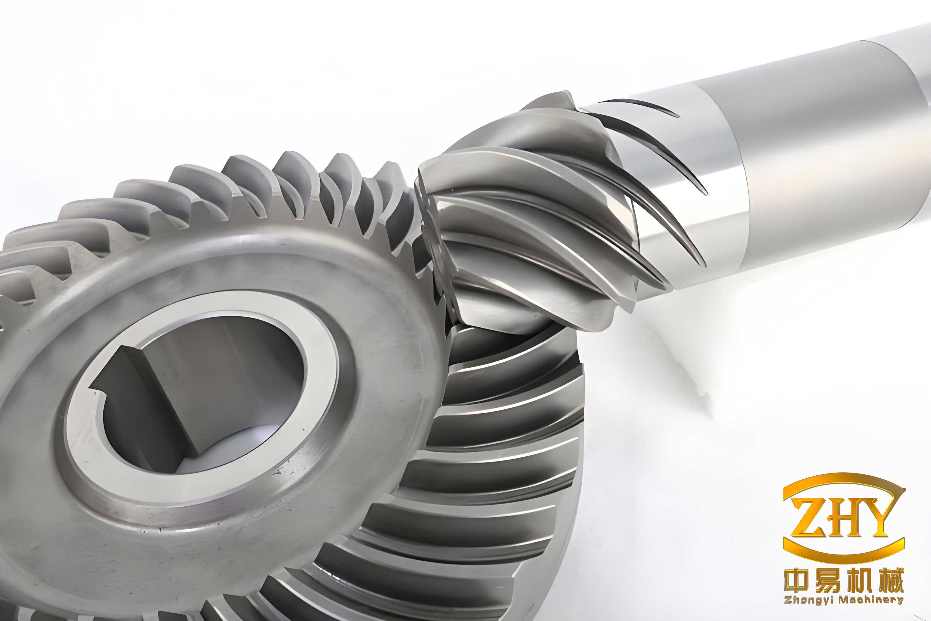
The problem emerged during the development of a spiral bevel gear set for a bus rear axle. The driven spiral bevel gear, with specific technical requirements, exhibited irregular contact patterns after heat treatment. These patterns, analyzed on a Gleason 600HTT rolling tester, showed either游离 (wandering) or uneven spot sizes, indicating potential gear misalignment. Initially, all heat treatment inspections—surface hardness, core hardness, case depth, flatness, and roundness—met the specifications, as shown in Table 1. This suggested that the issue might stem from subtle distortions not captured by standard metrics. The production workflow involved multiple steps: sawing, induction heating, forging, ring rolling, upsetting, isothermal normalizing, rough turning, high-temperature tempering, finish turning, gear milling, heat treatment (pre-oxidation, heating, carburizing, diffusion, pre-cooling, stabilizing, press-quenching, washing, tempering), shot blasting, bore machining, gear lapping, phosphating, and contact pattern inspection. Given that cold machining processes were verified through runout checks, the root cause was traced back to heat treatment, prompting a detailed investigation.
| Parameter | Specification | Measured Value |
|---|---|---|
| Surface Hardness (HV) | ≥670 | 693 |
| Core Hardness (HV) | 320–450 | 449 |
| Case Depth (mm) at HV550 | 1.3–1.8 | 1.67 |
| Flatness (mm): Inner/Outer Edge | ≤0.10 | Inner: ≤0.05, Outer: ≤0.10 |
| Roundness (mm, internal control) | ≤0.06 | 0.03–0.04 |
Our first step was to scrutinize the heat treatment and press-quenching parameters. The carburizing process was conducted in a controlled atmosphere furnace, with zones for pre-oxidation, heating, carburizing, diffusion, and cooling. The press-quenching involved a hydraulic press with specific pressure settings and oil cooling. However, we observed that the oil temperature was not consistently maintained; it started at ambient conditions (10–30°C) and rose to around 50°C during quenching. This variability in oil temperature, especially when lower than optimal, reduced fluidity and led to non-uniform cooling, causing localized tooth distortions. Although post-quench flatness met standards, the spiral bevel gear teeth exhibited subtle deformations that manifested as contact pattern issues. Additionally, the core hardness was at the upper limit of the specification, suggesting that reducing it might minimize distortion. We hypothesized that optimizing the quenching process could improve consistency.
| Process Stage | Temperature (°C) | Carbon Potential (%) | Duration/Notes |
|---|---|---|---|
| Pre-oxidation | 500 (increased from 450) | — | — |
| Heating Zone I | 850 (reduced from 900) | — | — |
| Heating Zone II | 880 (reduced from 900) | — | — |
| Carburizing Zone I | 910 | 1.0 | — |
| Carburizing Zone II | 910 | 0.9 | — |
| Diffusion Zone | 900 | 0.80 | — |
| Pre-cooling Zone | 850 | 0.75 | — |
| Stabilizing Zone | 840 | 0.75 | — |
| Tempering | 170 | — | — |
| Quench Oil Temperature | 70 ± 5 (increased from 50 ± 5) | — | MASTA oil, circulated for ≥20 min before quenching |
To address this, we revised the press-quenching protocol. The original process involved three stages of oil flow with varying durations and pressures. We increased the first stage duration from 20 seconds to 60 seconds to ensure initial uniform cooling, reduced the second-stage oil flow rate from 1130 L/min to 960 L/min, and decreased the third stage from 90 seconds to 60 seconds. The oil temperature was stabilized at 70°C ± 5°C, with pre-circulation to guarantee consistency. Moreover, we enforced a post-quench check where the inner edge flatness had to be greater than the outer edge, ensuring a controlled concave distortion that could be compensated during gear lapping. The press-quenching parameters are summarized in Table 3.
| Parameter | Value |
|---|---|
| Inner Ring Pressure (MPa) | 1.5 |
| Outer Ring Pressure (MPa) | 3.5 |
| Expander Pressure (MPa) | 0.8 |
| Pulsation Frequency (Hz) | 30 |
| Stage 1: All Channels (A, B, C) Open | 60 seconds (increased from 20s) |
| Stage 2: Channels A and C Open | Oil flow: 960 L/min (reduced from 1130 L/min) |
| Stage 3: All Channels Open | 60 seconds (reduced from 90s) |
| Base Die Setting | +1 (adjusted for consistency) |
| Quench Oil Temperature | 70°C ± 5°C |
Next, we examined the raw material and forging processes. The steel used for the spiral bevel gear was 22CrMoH, with a specified hardenability range. Chemical analysis, macrostructure, and segregation tests were within norms, but the actual hardenability was at the upper limit: J15 = 40 HRC against a requirement of 35–40 HRC. High hardenability can lead to excessive core hardness and increased distortion risk. We measured the billet hardness at three symmetric points (120° apart), obtaining values of 179 HBW, 181 HBW, and 180 HBW, which met the specification of 175–195 HBW. Metallographic examination revealed a ferrite-pearlite structure with some banding, typical for forged components. The forging flow lines were aligned with the gear geometry, but non-uniformities could contribute to residual stresses.
To mitigate these stresses, we considered the normalizing process. Initially, the spiral bevel gear underwent isothermal normalizing after forging, followed by rough turning and a high-temperature temper at 520°C for 2 hours. This tempering temperature was relatively low for stress relief; typically, temperatures around 640°C are used without significantly reducing hardness. For large-module spiral bevel gears, we recommend a second normalizing after rough turning. This ensures more uniform material removal and stress distribution. Although it adds process steps, it can enhance dimensional stability. We had 20 billets available and subjected them to a second normalizing. Post-normalizing hardness remained similar (182 HBW, 180 HBW, 179 HBW), but the microstructure showed finer grain refinement, as seen in metallurgical images. This refinement improves toughness and reduces distortion propensity.
The heat treatment of spiral bevel gears involves complex thermal gradients and phase transformations. The distortion during quenching can be modeled using the following equation for thermal stress, which influences dimensional changes:
$$ \sigma_{thermal} = E \alpha \Delta T $$
where \( E \) is Young’s modulus, \( \alpha \) is the coefficient of thermal expansion, and \( \Delta T \) is the temperature difference during cooling. For a spiral bevel gear, non-uniform cooling can lead to varying \( \Delta T \) across the tooth profile, causing distortions that affect contact patterns. Additionally, the case depth evolution during carburizing follows Fick’s law, and the effective case depth \( d \) at a hardness threshold can be approximated by:
$$ d = k \sqrt{t} $$
where \( k \) is a material-dependent constant and \( t \) is time. Over-carburizing can increase surface hardness but also residual stresses. Our optimized process balanced these factors to achieve the specified case depth of 1.3–1.8 mm while minimizing distortions.
After implementing the optimized heat treatment and press-quenching, we tested 10 spiral bevel gears from the second-normalized batch. Three were used for parameter tuning, and seven were production units. The tuning samples showed flatness variations, but the production gears met all dimensional criteria: inner edge flatness > outer edge, with inner edge ≤0.10 mm. Contact pattern tests on the Gleason tester indicated that only one gear exhibited slight wandering; the others were acceptable. However, after phosphating—a manganese-based coating process at 90–95°C—some gears showed contact pattern shifts, particularly on the concave side偏向大端 (biased toward the heel). This suggested that residual stresses from gear lapping or non-uniform phosphating might be factors.
To investigate, we analyzed the gear lapping process, which involved a load of 10 N·m and 220-grit abrasive. Higher lapping loads induce more subsurface stresses, which can relax during phosphating due to thermal exposure. We conducted an experiment: after lapping, gears were heated to 100°C for 1 hour to simulate stress relief, and contact patterns were rechecked. The patterns elongated, confirming stress relaxation effects. Consequently, we reduced the lapping load and increased lapping time to minimize stress incorporation. Additionally, we adjusted the tempering temperature slightly higher to lower surface hardness, enhancing stress relief without compromising wear resistance.
The contact pattern shift post-phosphating in spiral bevel gears is primarily attributed to localized distortions from heat treatment. During lapping, contact patterns are checked at symmetric points (e.g., 120° intervals), but if distortions are uneven, some tooth regions may not be inspected, leading to hidden irregularities. Phosphating, being a chemical coating process, can accentuate these irregularities due to varying growth rates on different tooth curvatures. Our strategy involved setting the pre-phosphating contact pattern slightly toward the toe on the concave side and keeping the convex side neutral. This compensated for post-phosphating shifts, increasing the qualification rate from 40% to 80%.
Further improvements involved material selection. For driven spiral bevel gears, we now prefer steels with hardenability in the mid-to-lower range, such as 20CrMnTiH with J15 around 36 HRC, rather than upper-limit grades like 22CrMoH. This helps maintain core hardness in the 320–380 HV range, reducing quenching stresses and distortions. The relationship between hardenability and core hardness can be expressed using the Grossmann equation:
$$ D_I = k \cdot \sqrt{J} $$
where \( D_I \) is the ideal critical diameter, \( k \) is a constant, and \( J \) is the hardenability index. Lower \( J \) values result in reduced through-hardening, beneficial for distortion control in large spiral bevel gears.
Our comprehensive approach included multiple optimizations: second normalizing of billets, refined press-quenching parameters, controlled oil temperature, adjusted lapping procedures, and material specification tweaks. The cumulative effect significantly enhanced the qualification rate of press-quenched spiral bevel gears. Table 4 summarizes the key measures and their impacts on spiral bevel gear quality.
| Measure | Description | Impact on Spiral Bevel Gear |
|---|---|---|
| Second Normalizing | Performed after rough turning to refine grain structure and relieve stresses | Improved dimensional stability and reduced distortion |
| Optimized Press-Quenching | Adjusted oil temperature, flow rates, and stage durations for uniform cooling | Enhanced consistency in tooth geometry and contact patterns |
| Material Hardenability Control | Selected steels with mid-to-lower hardenability for driven gears | Lower core hardness, minimizing quenching stresses |
| Lapping Process Adjustment | Reduced load and increased time to decrease residual stresses | Less post-phosphating pattern shift |
| Phosphating Pre-compensation | Set contact patterns slightly off-center pre-phosphating | Compensated for coating-induced deviations |
In conclusion, the production of high-quality spiral bevel gears demands a holistic view of the entire manufacturing chain. From material choice to final coating, each step influences the geometric integrity and performance of the spiral bevel gear. Our experience underscores that even when standard inspections pass, subtle distortions can arise from thermal process variabilities. By implementing second normalizing, optimizing press-quenching parameters, controlling oil temperature, and fine-tuning secondary processes, we achieved a notable increase in the qualification rate of press-quenched spiral bevel gears. Future work will focus on predictive modeling of distortions using finite element analysis to further refine heat treatment protocols for spiral bevel gears. The spiral bevel gear remains a cornerstone of automotive transmissions, and continuous improvement in its manufacturing is essential for advancing vehicle reliability and efficiency.
Throughout this journey, we’ve learned that attention to detail in heat treatment is paramount for spiral bevel gears. The interplay between cooling rates, material properties, and post-treatment stresses dictates the final gear quality. By sharing these insights, we hope to contribute to the broader industry’s efforts in producing more reliable and durable spiral bevel gears for automotive applications. The spiral bevel gear, with its intricate design, will continue to evolve, and our commitment to excellence drives us to explore new frontiers in gear manufacturing technology.