
I investigated the origin of point-like surface defects that appeared on a forged gear blank made from 20CrMnTi steel. The forged gear blank was produced through a sequence of electric arc furnace melting, ladle refining, vacuum degassing, continuous casting into square billets, hot charging into a continuous reheating furnace, continuous rolling into round bars, finishing, sawing, heating in a resistance furnace, die forging, and turning. During turning of the forged gear blank, I found small point defects on the machined surface. A careful examination of the as-forged surface of the same forged gear blank also revealed similar point defects, although they were less sharply delineated. Because such defects can affect fatigue life, tooth root strength, and dimensional quality of the final gear, I used macroscopic observation, chemical composition analysis, scanning electron microscopy, energy-dispersive X-ray spectroscopy, and metallographic examination to determine their cause. The evidence shows that refractory particles from the heating furnace adhered to the steel surface before hot forging and were pressed into the forged gear blank during forging. This article presents the detailed inspection results, the proposed formation mechanism, and the recommended preventive measures for avoiding similar surface defects on a forged gear blank.
1. Background and Process Context
20CrMnTi is a low-carbon low-alloy structural steel that is widely used for shafts, gears, and other transmission components. Its hardenability, toughness, and wear resistance after carburizing and quenching make it suitable for heavy-duty gear applications. The forged gear blank examined in this work was made from 20CrMnTi steel and followed a conventional industrial route. The process route is summarized in Table 1. Each stage can introduce different surface conditions, internal quality variations, or contamination. Therefore, I considered the entire process chain before attributing the point defects to a single operation.
| Stage | Purpose | Typical thermal condition | Potential surface interaction |
|---|---|---|---|
| Electric arc furnace melting | Melt scrap and alloy additions | High-temperature liquid steel | Slag, refractory erosion, endogenous inclusions |
| Ladle refining | Desulfurization, inclusion modification | Liquid steel with slag layer | Refractory reaction, reoxidation |
| Vacuum degassing | Hydrogen and nitrogen removal | Low pressure, liquid steel | Minor reoxidation if sealing fails |
| Continuous casting | Solidify into square billets | Mold and secondary cooling | Mold flux, oscillation marks, surface cracks |
| Hot charging and continuous rolling | Reheat and roll into round bars | Furnace heating and hot deformation | Furnace scale, rolled-in oxide, refractory particles |
| Finishing and sawing | Dimension control and billet preparation | Ambient temperature | Mechanical damage, saw marks |
| Resistance furnace heating | Reheat for die forging | High-temperature radiant heating | Refractory spalling, oxidation, decarburization |
| Die forging | Form the forged gear blank | Hot plastic deformation | Foreign particle embedding, surface folding |
| Turning | Machine the forged gear blank to near-net shape | Ambient temperature | Reveals subsurface defects, introduces tool marks |
The forged gear blank in this study was examined after turning and also in the as-forged condition. I noted that the point defects were visible on both surfaces, but they appeared more distinct after turning. This observation suggested that the defects were not created by the turning operation itself but were already present on or just beneath the surface of the forged gear blank. The challenge was to determine whether the defects originated from steelmaking, continuous casting, rolling, heating, or forging. I therefore combined chemical, microstructural, and microchemical evidence to isolate the most probable source.
For a low-alloy steel such as 20CrMnTi, the carbon equivalent is often used as a first indicator of hardenability and transformation behavior. I calculated the carbon equivalent using the following expression:
$$CE = C + \frac{Mn}{6} + \frac{Cr + Mo + V}{5} + \frac{Ni + Cu}{15}$$
Using the measured composition, the carbon equivalent of the forged gear blank was approximately:
$$CE = 0.21 + \frac{1.02}{6} + \frac{1.18 + 0.01 + 0}{5} + \frac{0.04 + 0.05}{15} \approx 0.624$$
This value is consistent with a medium-hardenability low-alloy steel and does not indicate any abnormal composition that would cause surface point defects. The chemical composition analysis is discussed in more detail later, but the initial assessment supported the view that the base metal of the forged gear blank was within specification.
2. Inspection Methods
I used a multi-scale inspection strategy to characterize the defects on the forged gear blank. The methods included macroscopic observation, chemical composition analysis, scanning electron microscopy with energy-dispersive X-ray spectroscopy, cross-sectional analysis, metallographic examination, and direct analysis of the refractory material in the heating furnace. Table 2 summarizes the methods, equipment, and objectives. The purpose of this approach was to compare the surface defects with potential sources in the process, especially the heating furnace and the forging operation.
| Method | Equipment or condition | Objective |
|---|---|---|
| Macroscopic observation | Visual inspection, low-magnification imaging | Record defect shape, size, color, and distribution on the forged gear blank |
| Chemical composition analysis | Optical emission spectrometry or equivalent | Verify that the 20CrMnTi steel met the required specification |
| Scanning electron microscopy | SEM with secondary and backscattered electron detectors | Observe surface morphology and cross-sectional features |
| Energy-dispersive X-ray spectroscopy | EDS attached to SEM | Identify elemental composition of particles and oxide layers |
| Cross-sectional analysis | Sectioning, mounting, grinding, polishing | Reveal pit geometry, oxide layers, and matrix deformation |
| Metallographic examination | Optical microscope after nitric acid ethanol etching | Evaluate microstructure and decarburization near defects |
| Refractory material analysis | Cold mounting, polishing, carbon coating, SEM-EDS | Compare furnace refractory particles with defect particles |
I paid particular attention to the forged gear blank surface because the defects were small and could easily be overlooked during routine inspection. The combination of surface and cross-sectional analyses allowed me to distinguish between surface contamination, embedded foreign matter, and indigenous non-metallic inclusions. I also compared the defects found on the as-forged surface with those exposed by turning, because turning removes a thin surface layer and can reveal the depth and shape of a defect more clearly.
3. Results
3.1 Macroscopic Observation
After turning, the surface of the forged gear blank showed distinct point defects. These defects were approximately circular and had a clear boundary with the surrounding matrix. The contrast between the defect and the matrix was strong, which made them easy to identify. Before turning, the as-forged surface of the same forged gear blank also showed similar point defects, but the color difference was less sharp and the boundary was less distinct. The defect shape was still approximately circular, and the distribution appeared random. Table 3 summarizes the macroscopic features of the defects on the forged gear blank before and after turning.
| Condition of forged gear blank | Defect shape | Boundary with matrix | Color contrast | Distribution |
|---|---|---|---|---|
| As-forged surface | Approximately circular | Gradual, not sharp | Moderate color difference | Random |
| After turning | Approximately circular | Distinct and irregular | Strong contrast | Random |
The circular shape was important. If the defects had originated from rolling, they would normally be elongated along the rolling direction. The nearly round morphology suggested that the defects formed after the last rolling pass and therefore pointed toward the forging stage. I also noted that the defects were not arranged in a linear or periodic pattern, which ruled out many machining-related causes such as tool chatter, feed marks, or fixture damage. The defects appeared as isolated points on the forged gear blank, and their random distribution was consistent with accidental contamination from the furnace environment.
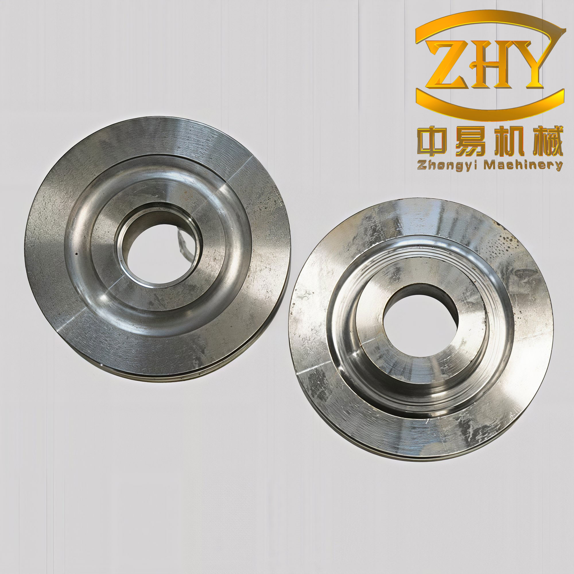
The visual evidence from the forged gear blank showed that the defects were not shallow scratches or handling marks. They appeared to be embedded into the surface, because turning did not remove them completely but instead made their boundaries sharper. This behavior indicated that the defects extended below the original surface and were likely associated with foreign material pressed into the forged gear blank during hot deformation.
3.2 Chemical Composition Analysis
I cut a specimen from the forged gear blank and analyzed its chemical composition. The results are shown in Table 4. The measured values for carbon, manganese, silicon, chromium, phosphorus, sulfur, copper, nickel, molybdenum, and titanium all fell within the specified range of GB/T 3077—2015 for 20CrMnTi steel. This result was important because it ruled out gross composition errors, such as excessive sulfur or phosphorus, as the direct cause of the point defects. Although composition alone cannot prove the absence of all steelmaking defects, it provided a baseline for the subsequent microchemical analysis.
| Element | Measured mass fraction (%) | Specified range (%) | Compliance |
|---|---|---|---|
| C | 0.21 | 0.17–0.23 | Yes |
| Mn | 1.02 | 0.80–1.10 | Yes |
| Si | 0.28 | 0.17–0.37 | Yes |
| Cr | 1.18 | 1.00–1.30 | Yes |
| P | 0.012 | ≤0.030 | Yes |
| S | 0.003 | ≤0.030 | Yes |
| Cu | 0.05 | ≤0.30 | Yes |
| Ni | 0.04 | ≤0.30 | Yes |
| Mo | 0.01 | ≤0.10 | Yes |
| Ti | 0.07 | 0.04–0.10 | Yes |
The carbon equivalent based on the measured composition was approximately 0.624, as calculated earlier. This value is normal for a 20CrMnTi forged gear blank and does not suggest any unusual segregation or alloying problem. I therefore concluded that the chemical composition of the forged gear blank was acceptable and that the point defects had to be explained by a physical or mechanical interaction at the surface rather than by a bulk chemistry error.
3.3 Scanning Electron Microscopy and Energy-Dispersive X-ray Spectroscopy
I cut specimens from the defect regions of the forged gear blank, cleaned them ultrasonically, and examined them with scanning electron microscopy. In the turned condition, the defect boundary was sharp and irregular. The matrix appeared bright, while the defect contained black-gray foreign matter. In the as-forged condition, the boundary between the defect and the matrix was less obvious. The matrix appeared light gray, the interface region appeared dark gray, and the center of the defect showed white contrast because of charge accumulation. Despite these differences in contrast, the microscopic features of the foreign matter were consistent in both conditions.
At higher magnification, the dark-gray and black particles inside the defects showed two distinct morphologies. Energy-dispersive X-ray spectroscopy identified these particles as alumina and aluminosilicate. The first type was rich in aluminum and oxygen, consistent with Al2O3. The second type contained aluminum, silicon, and oxygen, consistent with an aluminosilicate phase such as mullite, Al6Si2O13. Table 5 summarizes the EDS results from the particles observed on the forged gear blank surface.
| Particle type | Major elements detected | Identified phase | Typical morphology |
|---|---|---|---|
| Dark-gray particle | Al, O | Al2O3 (alumina) | Angular, blocky |
| Black particle | Al, Si, O | Al6Si2O13 (mullite or aluminosilicate) | Irregular, clustered |
The presence of alumina and aluminosilicate inside the defects was a strong clue. These phases are common constituents of refractory materials used in high-temperature furnaces. They are not typical products of steel solidification or rolling. If the defects had been caused by steelmaking slag or endogenous inclusions, I would expect to see complex oxides containing calcium, magnesium, manganese, or sulfur in addition to aluminum and silicon. The relatively simple Al–O and Al–Si–O chemistry pointed instead to an external refractory source.
I also considered the possibility that the particles were introduced during machining. However, the cutting tool, fixture, and coolant are not alumina- or mullite-rich in the same way as furnace refractory. In addition, the defects were present before turning, as confirmed by examination of the as-forged surface of the forged gear blank. This observation eliminated machining as the primary cause. The EDS evidence therefore directed attention to the heating furnace and the forging operation.
3.4 Refractory Material Analysis
To test the hypothesis that the particles came from the furnace, I inspected the resistance heating furnace used before die forging. I found many exfoliated refractory particles in the furnace. I randomly selected several particles, cold-mounted them, ground and polished them, coated them with carbon, and examined them by SEM-EDS. The particles showed different colors and morphologies, and EDS identified them as alumina and aluminosilicate. These phases matched the particles found in the defects on the forged gear blank. Table 6 lists the phases observed in the furnace refractory material.
| Particle appearance | Identified phase | Chemical formula | Possible origin in furnace |
|---|---|---|---|
| White, angular | Alumina | Al2O3 | High-alumina refractory brick or castable |
| Gray, irregular | Mullite | Al6Si2O13 | Aluminosilicate refractory lining |
The match between the furnace refractory particles and the defect particles was strong. The furnace lining had cracked and spalled, producing small particles that could adhere to the steel surface. During heating, the forged gear blank surface was exposed to these particles. When the steel was subsequently die forged, the particles were pressed into the surface. This mechanism explains why the defects were nearly circular: a small refractory particle pressed into the surface creates a localized indentation or embedded particle, and the surrounding metal flows around it. It also explains why the defects were found randomly on the forged gear blank rather than in a pattern.
3.5 Cross-Sectional Analysis
I sectioned one of the defects along its edge and prepared a polished cross-section. Scanning electron microscopy of the cross-section showed that the defect was a U-shaped pit. The pit had a clear boundary with the matrix. Along the matrix edge, I observed a thin layer of iron oxide. I did not find granular inclusions in the matrix adjacent to the pit. Inside the pit, I found light-gray iron oxide and dark-gray to black particles. EDS analysis of these dark particles gave the same Al–O and Al–Si–O signatures as the surface particles.
The cross-sectional morphology provided several important clues. First, the U-shaped profile indicated that material had been mechanically displaced or removed at the surface, which is consistent with a particle being pressed into the forged gear blank. Second, the iron oxide layer at the matrix edge suggested that the surface had been oxidized at high temperature before or during forging. Third, the absence of deformation flow lines around the pit indicated that the particle was not an indigenous inclusion that had been rolled or forged with the matrix. Instead, the particle was an external object that interacted with the surface during the final hot deformation.
Oxidation during heating can be described by a parabolic rate law:
$$x = k_p \sqrt{t}$$
where \(x\) is the oxide thickness, \(k_p\) is the parabolic rate constant, and \(t\) is time. The instantaneous oxidation rate is:
$$\frac{dx}{dt} = \frac{k_p}{2\sqrt{t}}$$
Thermal stresses generated during heating and cooling can also promote scale cracking and refractory spalling. A simplified thermal stress expression is:
$$\sigma_{th} = \frac{E \alpha \Delta T}{1-\nu}$$
where \(E\) is Young’s modulus, \(\alpha\) is the coefficient of thermal expansion, \(\Delta T\) is the temperature change, and \(\nu\) is Poisson’s ratio. When the thermal stress exceeds the strength of the refractory or the oxide scale, cracking and spalling can occur. This provides a plausible explanation for the generation of refractory particles in the furnace and the formation of the iron oxide layer on the forged gear blank surface.
The adhesion of a particle to the steel surface before forging can be influenced by van der Waals forces, electrostatic forces, and mechanical interlocking. A simplified adhesion force model is:
$$F_{ad} = \mu N + F_{electrostatic}$$
where \(\mu\) is the friction coefficient, \(N\) is the normal load, and \(F_{electrostatic}\) represents electrostatic attraction. Once the particle adheres, the forging pressure can embed it into the surface. The local embedding pressure can be approximated by:
$$P_{embed} = \frac{F_{forge}}{A_{contact}}$$
where \(F_{forge}\) is the forging force and \(A_{contact}\) is the real contact area between the particle and the steel surface. High forging pressure and small contact area favor deep embedding. This is consistent with the observation that the defect particles were pressed into the forged gear blank rather than remaining loosely on the surface.
3.6 Metallographic Examination
After etching with nitric acid ethanol, I examined the defect region with an optical microscope. The matrix far from the defect showed a normal microstructure of ferrite and pearlite, which is expected for 20CrMnTi steel in the as-forged or normalized condition. Near the pit edge, I observed decarburization. The decarburized zone was ferrite-rich, which indicated that the surface had been exposed to a high-temperature oxidizing atmosphere. Table 7 summarizes the microstructural features observed near the defect in the forged gear blank.
| Zone | Microstructure | Interpretation |
|---|---|---|
| Matrix far from defect | Ferrite and pearlite | Normal 20CrMnTi microstructure |
| Pit edge | Ferrite-rich, decarburized | High-temperature exposure and carbon loss |
| Interface | Thin iron oxide layer | Oxidation during heating |
| Pit interior | Alumina and aluminosilicate particles | Embedded refractory fragments |
The decarburized layer is a particularly useful indicator. Decarburization occurs when carbon diffuses out of the steel surface at high temperature in an oxidizing atmosphere. The depth of decarburization depends on temperature, time, atmosphere, and steel composition. A simplified diffusion description is given by Fick’s second law:
$$\frac{\partial C}{\partial t} = D \frac{\partial^2 C}{\partial x^2}$$
where \(C\) is carbon concentration, \(t\) is time, \(D\) is the diffusion coefficient, and \(x\) is distance from the surface. The presence of decarburization near the pit edge confirms that the defect region experienced a high-temperature excursion before or during forging. It also supports the conclusion that the foreign particles were introduced at the heating stage, because the oxidized and decarburized zone formed around the embedded particle.
4. Comprehensive Analysis
I integrated the chemical, microstructural, and microchemical evidence to determine the origin of the point defects on the forged gear blank. The chemical composition of the forged gear blank met the specification, so a bulk composition error was not responsible. The defects were approximately circular and randomly distributed, which ruled out a directional rolling origin. If the defects had formed during rolling, they would have been elongated along the rolling direction. The rolling process elongates inclusions and surface contaminants according to the reduction ratio. The rolling elongation can be expressed as:
$$\lambda = \frac{L_f}{L_0}$$
where \(L_0\) and \(L_f\) are the lengths before and after rolling. The equivalent strain is:
$$\varepsilon = \ln\left(\frac{A_0}{A_f}\right)$$
where \(A_0\) and \(A_f\) are the initial and final cross-sectional areas. A rolled-in defect would therefore show a high aspect ratio and a preferred orientation. The observed defects on the forged gear blank did not show this feature. They were round and isolated, indicating that they formed after rolling, during the heating and forging stages.
The defects were present on the as-forged surface and became more distinct after turning. This ruled out turning as the cause. The defect particles contained alumina and aluminosilicate, which matched the refractory material in the resistance heating furnace. The cross-sectional analysis showed a U-shaped pit with an iron oxide layer and a decarburized zone. There were no deformation flow lines around the pit, which indicated that the particle was not an indigenous inclusion formed during solidification. Instead, the particle was an external object that adhered to the surface and was pressed into the forged gear blank during hot forging.
The forging process itself involves high temperature and high pressure. The flow stress of 20CrMnTi during hot deformation can be described by a constitutive equation of the form:
$$\sigma = K \varepsilon^n \dot{\varepsilon}^m$$
where \(\sigma\) is the flow stress, \(K\) is the strength coefficient, \(\varepsilon\) is the strain, \(n\) is the strain-hardening exponent, \(\dot{\varepsilon}\) is the strain rate, and \(m\) is the strain-rate sensitivity. At forging temperature, the flow stress is lower than at room temperature, but the forging pressure is still sufficient to embed small refractory particles into the surface. The friction between the die and the workpiece also contributes to surface deformation. The friction force can be approximated as:
$$F_f = \mu F_N$$
where \(F_f\) is the friction force, \(\mu\) is the friction coefficient, and \(F_N\) is the normal force. Friction can drag particles along the surface and press them into the forged gear blank. The penetration depth of a spherical particle into a plastically deforming surface can be estimated by:
$$h = \frac{d}{2}\left(1 – \cos \theta\right)$$
where \(h\) is the penetration depth, \(d\) is the particle diameter, and \(\theta\) is the contact angle. This simplified geometric relation shows that larger particles and higher contact angles produce deeper pits, which is consistent with the U-shaped defects observed on the forged gear blank.
Table 8 summarizes the discrimination of possible defect sources. I evaluated melting inclusions, rolling scale, machining damage, and forging furnace refractory particles against the observed evidence. Only the forging furnace refractory mechanism was consistent with all observations.
| Possible source | Expected morphology | Expected chemistry | Observed on forged gear blank? | Conclusion |
|---|---|---|---|---|
| Melting inclusion | Elongated, directional, internal | Ca–Al–Si–O, MnS, etc. | No | Ruled out |
| Rolling scale | Elongated, parallel to rolling direction | Iron oxides, mill scale | No | Ruled out |
| Machining damage | Regular tool marks, fresh surface | No foreign oxide | No | Ruled out |
| Furnace refractory | Round, U-shaped pit, oxide layer | Al2O3, Al6Si2O13 | Yes | Confirmed |
The mechanism can be summarized as follows. The resistance heating furnace lining degraded and spalled, producing small refractory particles composed mainly of alumina and mullite. These particles adhered to the surface of the forged gear blank during heating. The high temperature also caused oxidation and decarburization of the steel surface. During die forging, the forging pressure and friction pressed the refractory particles into the surface of the forged gear blank. After cooling and turning, the embedded particles and surrounding oxide layer were exposed as point defects. The defect boundary became sharper after turning because the machining operation removed the deformed surface layer and revealed the embedded particle more clearly.
5. Discussion
The formation of point defects on the forged gear blank is a surface contamination problem rather than a bulk steel quality problem. The chemical composition of the steel was correct, and the microstructure away from the defects was normal. The defects were localized and associated with foreign refractory particles. This distinction is important because corrective actions should target the heating furnace and the forging environment, not the steelmaking process alone.
The high-temperature exposure of the forged gear blank in the resistance furnace created conditions for both oxidation and decarburization. The oxide layer on the surface can act as a barrier or as a medium that traps refractory particles. The decarburized zone indicates that carbon diffused out of the surface. The depth of decarburization can be approximated by the diffusion length:
$$L_d \approx \sqrt{D t}$$
where \(L_d\) is the diffusion length, \(D\) is the diffusion coefficient, and \(t\) is time. Longer heating times and higher temperatures increase the diffusion length and therefore the decarburization depth. The presence of a decarburized zone near the defect suggests that the forged gear blank experienced a relatively long or hot heating cycle. Reducing the heating time or controlling the furnace atmosphere could minimize this effect.
The refractory particles themselves are brittle oxides. Under thermal cycling, the furnace lining can crack and spall. The spalling tendency depends on the thermal expansion mismatch, the temperature gradient, and the mechanical constraints. A simplified thermal shock parameter is:
$$R = \frac{\sigma_f (1-\nu)}{E \alpha}$$
where \(R\) is the thermal shock resistance, \(\sigma_f\) is the fracture strength, \(\nu\) is Poisson’s ratio, \(E\) is Young’s modulus, and \(\alpha\) is the thermal expansion coefficient. A low thermal shock resistance means that the refractory is more likely to crack under rapid temperature changes. Regular inspection and maintenance can detect cracks before large spalls occur.
The adhesion of refractory particles to the forged gear blank surface can also be influenced by the surface condition. A rough, oxidized surface provides more mechanical anchoring sites than a smooth, clean surface. Therefore, controlling scale formation and surface roughness before forging can reduce the probability of particle adhesion. In addition, the furnace atmosphere can affect both oxidation and adhesion. An oxidizing atmosphere promotes scale growth, while a reducing or neutral atmosphere can reduce scale thickness. However, a strongly reducing atmosphere may affect refractory stability, so a balanced atmosphere is preferred.
The forging operation itself can be optimized to reduce surface defect formation. For example, lowering the forging temperature within the allowable range can increase flow stress and may reduce particle embedding, but it can also increase die wear and reduce forgeability. Therefore, the forging parameters must be optimized together with the furnace conditions. The key process variables and recommended control measures are summarized in Table 9.
| Process variable | Risk for the forged gear blank | Recommended control | Expected benefit |
|---|---|---|---|
| Furnace refractory condition | Spalling and particle generation | Regular inspection, repair, or replacement | Reduces foreign particle source |
| Furnace atmosphere | Oxidation and decarburization | Control oxygen and carbon potential | Reduces scale and decarburization |
| Heating time | Excessive oxide growth and decarburization | Optimize schedule and avoid delays | Reduces surface degradation |
| Surface scale before forging | Particle adhesion and embedding | Descale or brush before forging | Improves surface cleanliness |
| Forging pressure and friction | Deep particle embedding | Optimize die design and lubrication | Reduces defect depth |
| Post-forging inspection | Escape of defective forged gear blanks | Implement surface inspection and turning checks | Prevents downstream failures |
The effect of a surface defect on the performance of the forged gear blank depends on its size, depth, and location. A point defect can act as a stress concentrator. The elastic stress concentration factor for a shallow pit can be approximated by:
$$K_t = 1 + 2\sqrt{\frac{d}{\rho}}$$
where \(d\) is the defect depth and \(\rho\) is the root radius of the defect. A sharper defect with a smaller root radius produces a higher stress concentration. The local stress is then:
$$\sigma_{local} = K_t \sigma_{nominal}$$
If the local stress exceeds the fatigue strength of the material, a fatigue crack can initiate. For gear applications, surface defects are particularly harmful because gear teeth experience cyclic bending and contact stresses. Therefore, preventing point defects on the forged gear blank is important for final product reliability.
The fatigue limit can be reduced by surface defects according to an area-based model:
$$\sigma_f = \sigma_{f0} \left(1 – \frac{A_d}{A_0}\right)$$
where \(\sigma_f\) is the fatigue limit with defects, \(\sigma_{f0}\) is the fatigue limit of the defect-free material, \(A_d\) is the projected area of the defect, and \(A_0\) is a reference area. Although this is a simplified expression, it illustrates the general trend: larger defects cause a greater reduction in fatigue strength. This reinforces the need to eliminate refractory particle embedding during forging.
6. Conclusions and Recommendations
I conclude that the point defects on the forged gear blank originated from the resistance heating furnace. The furnace lining degraded and spalled, producing refractory particles composed mainly of alumina and mullite. These particles adhered to the steel surface during heating. The surface was simultaneously oxidized and decarburized. During die forging, the particles were pressed into the forged gear blank, forming U-shaped pits with embedded foreign matter. Turning later exposed these defects more clearly, but turning did not cause them. The chemical composition of the forged gear blank was within specification, and no evidence of indigenous non-metallic inclusions or rolling-related elongation was found.
Based on these findings, I recommend the following actions to prevent recurrence of surface point defects on a forged gear blank:
1. Regularly inspect and maintain the resistance heating furnace lining. Replace or repair cracked and spalled refractory material before it generates loose particles.
2. Clean the furnace chamber periodically to remove broken refractory particles that can adhere to the forged gear blank surface.
3. Use refractory materials with better thermal shock resistance and mechanical stability to reduce spalling.
4. Control the furnace atmosphere to minimize oxidation and decarburization. Avoid excessive oxygen and moisture while maintaining safe combustion conditions.
5. Optimize the heating schedule. Reduce unnecessary holding time at high temperature to limit oxide scale growth and carbon diffusion.
6. Descale or clean the forged gear blank surface before die forging when possible. This reduces the chance of refractory particles sticking to the surface.
7. Optimize forging parameters, including temperature, deformation rate, and lubrication, to reduce excessive surface friction and particle embedding.
8. Implement surface inspection of the forged gear blank after forging and after turning. Use visual inspection, magnetic particle inspection, or other appropriate methods to detect point defects early.
9. Maintain traceability of furnace maintenance records and forging process parameters so that any future defect can be correlated with specific process conditions.
10. Train operators to recognize the difference between embedded refractory particles, scale, and machining marks. Early identification can prevent defective forged gear blanks from entering subsequent manufacturing steps.
Table 10 summarizes the key findings and corrective actions.
| Finding | Evidence | Corrective action |
|---|---|---|
| Refractory particles embedded in the forged gear blank | Al2O3 and Al6Si2O13 in defects and furnace lining | Inspect, repair, and clean furnace refractory |
| Surface oxidation and decarburization | Iron oxide layer and ferrite-rich zone near pit edge | Control furnace atmosphere and heating time |
| Round, randomly distributed defects | No rolling elongation or machining pattern | Focus on heating and forging stages |
| Defects visible before and after turning | As-forged surface already contained defects | Inspect forged gear blank before turning |
| Normal chemical composition | All elements within GB/T 3077—2015 | Maintain steelmaking practice; focus on surface protection |
The investigation shows that surface quality control for a forged gear blank must include the heating furnace, the handling system, and the forging operation. A small refractory particle can create a visible point defect that may reduce fatigue performance. By controlling the furnace lining, atmosphere, heating schedule, and forging parameters, the formation of such defects can be minimized. I recommend that the corrective actions in Table 10 be implemented as part of a routine quality management system for the production of 20CrMnTi forged gear blanks.