
In the realm of heavy-duty automotive drive axles, the spiral bevel gear set is the cornerstone of the main reduction unit. Among these, Gleason-system spiral bevel gears are predominantly employed due to their superior load-carrying capacity and smooth, quiet operation. The pinion (drive gear) is typically generated, while the gear (driven member) is form-cut. This treatise focuses on the mathematical modeling of the pinion tooth surface, specifically for a convex flank, as machined on a Gleason 118 hypoid generator. The primary objective is to establish a rigorous mathematical framework that transforms the machine’s physical adjustment parameters into a precise digital model of the theoretical tooth surface. This model serves as an indispensable foundation for subsequent analyses such as tooth contact analysis (TCA), measurement and evaluation of surface deviations, and the execution of finite element analysis (FEA) for stress and durability studies. This work, therefore, bridges the gap between shop floor settings and advanced digital engineering tools.
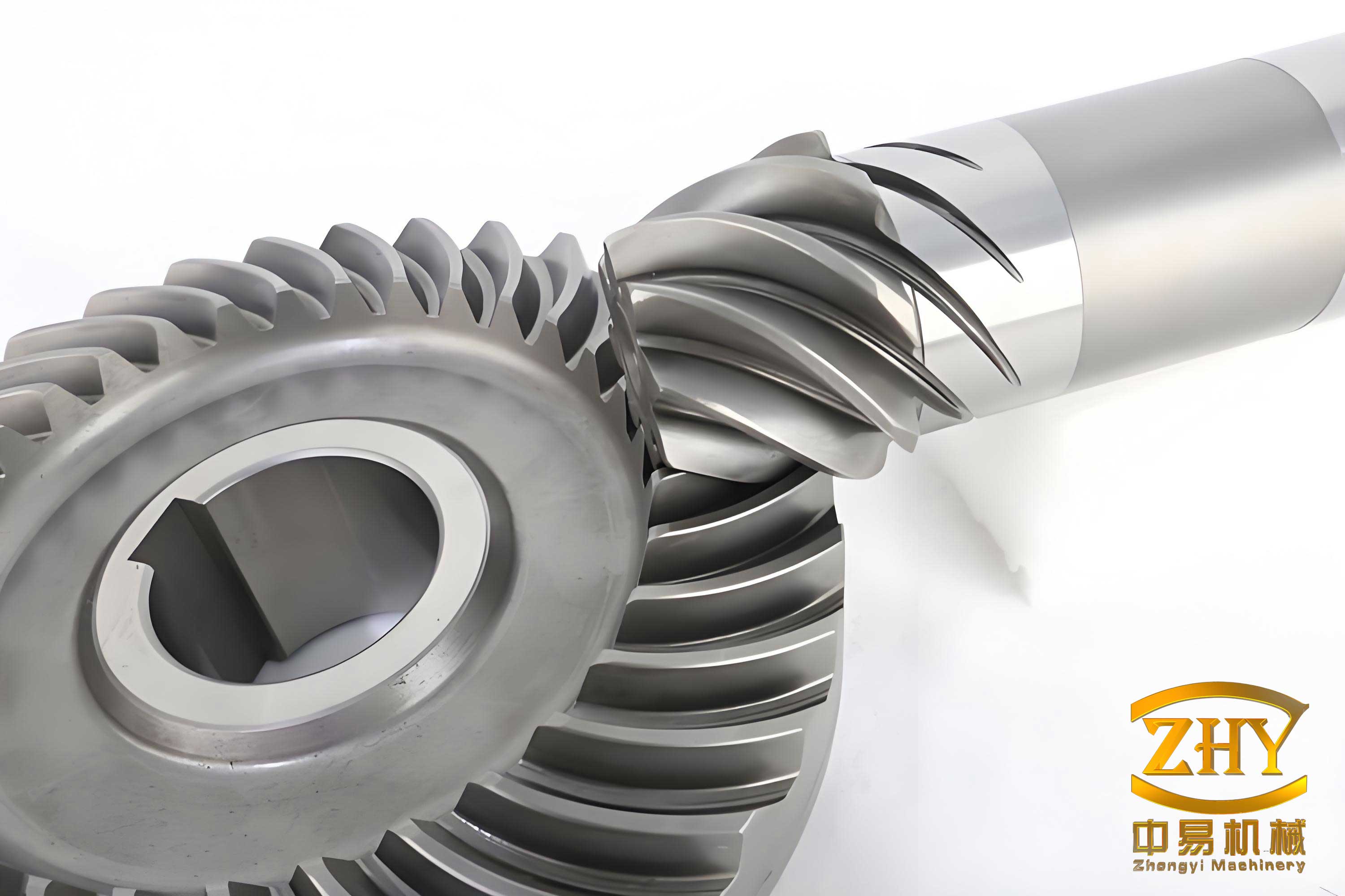
The generation of a spiral bevel gear tooth surface is a complex spatial enveloping process. On a Gleason 118 machine, a rotating cutter head, which simulates the profile of a basic crown gear, is mounted on a cradle. The cradle and the workpiece (gear blank) rotate in a precisely synchronized ratio, thereby “generating” the tooth surface through the relative motion between the cutter blades and the blank. Our task is to mathematically describe every component of this system—the cutter geometry, the cradle and workpiece positions, the intricate cutter tilt mechanism, and their coupled motions—to arrive at the equation of the generated spiral bevel gear surface.
1. Fundamentals of the Machining Principle
The manufacturing of a Gleason spiral bevel gear pair involves two distinct methods. The gear (larger member) is produced via the Formate or forming method, where the cutter head shape is directly impressed onto the workpiece with a simple indexing motion, devoid of a generating roll. Conversely, the pinion is produced by the Generated or enveloping method. Here, the rotating cutter head, positioned on the rolling cradle, acts as the imaginary generating gear (the crown gear). The synchronized rolling motion between the cradle (representing the crown gear) and the workpiece (the pinion blank) envelopes the correct conjugate tooth form onto the pinion. This generation process is crucial for ensuring localized bearing contact after final lapping and is the focus of our modeling efforts for the spiral bevel gear pinion.
2. Mathematical Definition of Coordinate Systems
The first step in modeling any mechanical system is the establishment of clear, right-handed Cartesian coordinate systems. For the Gleason 118 generator, two primary static frames are essential.
- Cradle Coordinate System \( S_M(O_M-x_M, y_M, z_M) \): This system is fixed to the machine bed. The origin \( O_M \) is at the cradle center. The \( z_M \)-axis coincides with the cradle axis of rotation. The \( x_M \)-axis is radially outward along the cradle face.
- Workpiece Coordinate System \( S_1(O_1-x_1, y_1, z_1) \): This system is fixed to the gear blank. The origin \( O_1 \) is located on the theoretical apex of the pinion blank. The \( z_1 \)-axis aligns with the pinion’s axis of rotation.
The relative positioning of the workpiece with respect to the cradle is defined by several classic machine settings. The position vector of \( O_1 \) expressed in the cradle system \( S_M \) is given by:
$$
\mathbf{O_1^{(M)}} = \begin{bmatrix}
X_p \cos\delta \\
-E \\
X_B + X_p \sin\delta
\end{bmatrix}
$$
Where the key machine settings are defined in the following table:
| Symbol | Machine Setting Name | Description |
|---|---|---|
| \( X_p \) | Sliding Base (Horizontal Offset) | Horizontal distance of pinion axis from cradle center. |
| \( E \) | Blank Offset (Vertical Offset) | Vertical distance of pinion axis from cradle center. |
| \( X_B \) | Machine Center to Back (Bed) | Axial position of pinion along its axis. |
| \( \delta \) | Machine Root Angle | Installation angle of the pinion axis relative to the cradle plane. |
The unit vector along the workpiece axis, expressed in \( S_M \), is \( \mathbf{p} = (\cos\delta,\, 0,\, \sin\delta) \).
3. The Cutter Head and the Essential Tilt Mechanism
The cutting tool is a circular cutter head holding multiple straight-sided blade inserts. Its geometry is defined by the point radius (or cutter radius) \( R_c \), blade angle \( \alpha \), and point width \( c \). In the Gleason 118, the cutter head’s spatial orientation is controlled by a sophisticated mechanism comprising a cutter tilt and a cutter swivel. This mechanism introduces the necessary eccentricity and inclination to position the cutter head correctly for cutting the curved tooth lengthwise of the spiral bevel gear.
We define three additional coordinate systems related to the cutter assembly:
- Cutter Coordinate System \( S_0(O_0-x_0, y_0, z_0) \): Fixed to the cutter head. \( z_0 \)-axis is the cutter rotation axis. A blade point lies initially in the \( x_0z_0 \)-plane.
- Tilt Coordinate System \( S_b(O_b-x_b, y_b, z_b) \): Attached to the tilt body. The tilt axis is \( y_b \).
- Swivel Coordinate System \( S_d(O_d-x_d, y_d, z_d) \): Attached to the swivel body. The swivel axis is \( y_d \). Systems \( S_b \) and \( S_d \) share the same origin.
The relative orientation is achieved by two rotations. First, the cutter system \( S_0 \) is tilted by an angle \( i \) (the total tool inclination angle) about the \( y_b \)-axis to align with \( S_b \). Second, the system \( S_b \) is swiveled by an angle \( j \) (the basic tool swivel angle) about the \( y_d \)-axis to align with \( S_d \). The angles \( i \) and \( j \) are not direct settings but are derived from the machine’s control angles: the tool inclination angle \( I \) and the tool swivel angle \( J \), incorporating the machine’s inherent 15-degree base angle. For a left-hand spiral bevel gear (as in our example), the relationships are:
$$
i = 2 \arcsin\left( \sin(I/2) \sin 15^\circ \right)
$$
$$
j = \operatorname{arccot}\left( \tan(I/2) \cos 15^\circ \right) – (\beta/2 – J + 180^\circ)
$$
where \( \beta \) is the mean spiral angle of the spiral bevel gear. Finally, the entire cutter assembly, represented by system \( S_d \), is positioned on the cradle. The Radial Distance \( S \) (also called the cutter radius setting) locates the cutter center along the cradle’s negative \( x_M \)-axis. It is calculated from the Basic Cutter Radius \( K \) and the spiral angle \( \beta \):
$$
S = 2K \sin(\beta/2)
$$
4. Derivation of the Theoretical Tooth Surface Equation
The generated surface is the envelope of successive positions of the cutter surface relative to the workpiece. According to the fundamental law of gearing, at the point of contact between two conjugate surfaces, their relative velocity must be orthogonal to the common surface normal. This gives the equation of meshing.
Let \( \mathbf{r} \) be the position vector of a contact point in the cradle system \( S_M \), and \( \mathbf{n} \) be its unit normal vector. The relative velocity \( \mathbf{V}^{(12)} \) between the cradle (body 1) and the workpiece (body 2) must satisfy:
$$
\mathbf{V}^{(12)} \cdot \mathbf{n} = 0
$$
The cradle rotates with angular velocity \( \omega_c \mathbf{k} \) (where \( \mathbf{k}=(0,0,1) \)), and the workpiece rotates with angular velocity \( \omega_w \mathbf{p} \). Their ratio is the machine roll ratio \( m_{wc} = \omega_w / \omega_c \). The relative velocity at a point \( \mathbf{r} \) is:
$$
\mathbf{V}^{(12)} = \omega_c \mathbf{k} \times \mathbf{r} – \omega_w \mathbf{p} \times (\mathbf{r} – \mathbf{O_1})
$$
Substituting and simplifying yields the meshing condition specific to our spiral bevel gear generator setup:
$$
[ \mathbf{k} \times \mathbf{r} – m_{wc} \, \mathbf{p} \times (\mathbf{r} – \mathbf{O_1}) ] \cdot \mathbf{n} = 0 \quad \text{(1)}
$$
To utilize Eq. (1), we must express \( \mathbf{r} \) and \( \mathbf{n} \) as functions of the cutter geometry parameters and the machine motions.
4.1. Cutter Surface and Coordinate Transformations
A point on a straight-sided cutter blade in its own system \( S_0 \) is defined by two parameters: the distance \( l \) from the blade reference point along its edge, and the rotation angle \( \theta_2 \) of the cutter. Let the unit vector along the blade face be \( \mathbf{F} = (\sin\alpha,\, 0,\, -\cos\alpha) \). The position vector from the cutter center to a point on the blade is \( \mathbf{c} + l\mathbf{F} \), where \( \mathbf{c} = (c, 0, 0) \) accounts for the point width. After the cutter rotates by \( \theta_2 \), the point’s coordinates are:
$$
\mathbf{r}_0(\theta_2, l) = \mathbf{R}( \mathbf{k}, \theta_2 ) (\mathbf{c} + l\mathbf{F})
$$
Its corresponding unit normal vector in \( S_0 \) is constant relative to the blade and given by \( \mathbf{n}_{01} = (-\cos\alpha,\, 0,\, -\sin\alpha) \). After cutter rotation:
$$
\mathbf{n}_0(\theta_2) = \mathbf{R}( \mathbf{k}, \theta_2 ) \mathbf{n}_{01}
$$
Where \( \mathbf{R}(\mathbf{a}, \phi) \) is the Rodrigues’ rotation matrix for rotating a vector about unit axis \( \mathbf{a} \) by angle \( \phi \). We now cascade the transformations through the tilt and swivel mechanisms, and finally to the cradle.
- From Cutter (\( S_0 \)) to Tilt (\( S_b \)): Rotate by angle \( i \) about \( y_b \)-axis (\( \mathbf{j}=(0,1,0) \)).
\( \mathbf{r}_b = \mathbf{R}(\mathbf{j}, i)\, \mathbf{r}_0 \), \( \mathbf{n}_b = \mathbf{R}(\mathbf{j}, i)\, \mathbf{n}_0 \). - From Tilt (\( S_b \)) to Swivel (\( S_d \)): Rotate by angle \( j \) about \( y_d \)-axis (same as \( y_b \) direction in its new orientation).
\( \mathbf{r}_d = \mathbf{R}(\mathbf{j}, j)\, \mathbf{r}_b \), \( \mathbf{n}_d = \mathbf{R}(\mathbf{j}, j)\, \mathbf{n}_b \). - From Swivel (\( S_d \)) to Cradle (\( S_M \)): First, translate by the radial distance \( \mathbf{S} = (S, 0, 0) \). Then, rotate by the cradle roll angle \( \theta_1 \).
The final position and normal in the cradle system are:
$$ \mathbf{r}(\theta_1, \theta_2, l) = \mathbf{R}( \mathbf{k}, \theta_1 ) ( \mathbf{r}_d + \mathbf{S} ) \quad \text{(2)} $$
$$ \mathbf{n}(\theta_1, \theta_2) = \mathbf{R}( \mathbf{k}, \theta_1 + j )\, \mathbf{n}_b \quad \text{(3)} $$
Note the crucial detail: the normal vector’s transformation from \( S_b \) to \( S_M \) involves an additional rotation by angle \( j \) because the tilt body’s orientation relative to the cradle includes the swivel.
4.2. Solving for the Tooth Surface
Equations (1), (2), and (3) define the generated spiral bevel gear surface parametrically. For a given cradle roll position \( \theta_1 \) (the generating motion parameter) and a cutter rotation angle \( \theta_2 \), the meshing equation (1) becomes a scalar equation in the single unknown parameter \( l \).
$$ f(\theta_1, \theta_2, l) = [ \mathbf{k} \times \mathbf{r}(\theta_1, \theta_2, l) – m_{wc} \, \mathbf{p} \times (\mathbf{r}(\theta_1, \theta_2, l) – \mathbf{O_1}) ] \cdot \mathbf{n}(\theta_1, \theta_2) = 0 $$
This equation is typically transcendental. For discrete values of \( \theta_1 \) and \( \theta_2 \), a numerical root-finding method (e.g., Newton-Raphson) is used to solve for \( l \). The triplet \( (\theta_1, \theta_2, l(\theta_1, \theta_2)) \) then defines a point on the theoretical tooth surface of the spiral bevel gear via Eq. (2). By varying \( \theta_1 \) across the generating roll range (from initial roll angle \( \theta_{10} \) to final roll angle \( \theta_{11} \)) and \( \theta_2 \) across a full revolution, a dense point cloud representing the entire generated flank can be computed.
5. Engineering Application: Modeling a Drive Axle Pinion
To demonstrate the practical application of the derived model, we consider the convex flank of a drive pinion from a heavy truck axle. The primary data for this spiral bevel gear is as follows:
| No. | Parameter | Symbol | Value |
|---|---|---|---|
| 1 | Number of Pinion Teeth | \( z_1 \) | 26 |
| 2 | Module | \( m \) | 8.63700 mm |
| 3 | Gear Ratio | \( z_2/z_1 \) | 33/26 |
| 4 | Mean Spiral Angle | \( \beta \) | 83.416667° |
| 5 | Hand of Spiral | – | Left |
The corresponding Gleason 118 machine settings for finishing this spiral bevel gear pinion are:
| No. | Machine Setting | Symbol | Value |
|---|---|---|---|
| 1 | Sliding Base | \( X_p \) | 7.48 mm |
| 2 | Blank Offset | \( E \) | -3.12 mm |
| 3 | Machine Center to Back | \( X_B \) | -1.89 mm |
| 4 | Machine Root Angle | \( \delta \) | 34.18° |
| 5 | Tool Inclination Angle | \( I \) | 4.47° |
| 6 | Tool Swivel Angle | \( J \) | -101.25° |
| 7 | Cutter Blade Angle | \( \alpha \) | 87.841082° |
| 8 | Roll Ratio | \( m_{wc} \) | 1.6557 |
| 9 | Point Width | \( c \) | 160.46 mm |
| 10 | Basic Cutter Radius | \( K \) | 111.125 mm |
| 11 | Initial Cradle Angle | \( \theta_{10} \) | 42.1388° |
| 12 | Final Cradle Angle | \( \theta_{11} \) | 75.1013° |
From settings 5 and 6, we first compute the derived tilt angles using the formulas in Section 3:
$$
i = 2 \arcsin\left( \sin(4.47^\circ/2) \sin 15^\circ \right) \approx 1.1567^\circ
$$
$$
j = \operatorname{arccot}\left( \tan(4.47^\circ/2) \cos 15^\circ \right) – (83.416667^\circ/2 – (-101.25^\circ) + 180^\circ) \approx 327.38275^\circ
$$
The radial distance is:
$$
S = 2 \times 111.125 \times \sin(83.416667^\circ/2) \approx 219.92 \text{ mm}
$$
Implementing the complete mathematical model with these parameters in computational software (e.g., MATLAB or Python) allows for the calculation of the tooth surface point cloud. The resulting three-dimensional model of the convex flank of the spiral bevel gear pinion accurately depicts its crowned and longitudinally curved geometry. This digital twin can be exported for visualization, comparison with coordinate measurement machine (CMM) data, or as input for finite element analysis meshing. The same methodology, with appropriate sign changes for the tool settings, is applied to model the concave flank of the pinion and the gear member’s teeth.
6. Conclusion and Forward Look
This work has presented a thorough, step-by-step derivation of the geometric model for a generated Gleason spiral bevel gear tooth surface, starting from the fundamental machine adjustment parameters of a Gleason 118 hypoid generator. By rigorously defining all coordinate systems, incorporating the critical tool tilt and swivel mechanism, and applying the fundamental law of gearing, we arrived at a closed system of equations that can be solved numerically to obtain the precise coordinates of the theoretical spiral bevel gear surface.
The resulting model is far more than an academic exercise. It serves as the essential “gold standard” for the spiral bevel gear. It enables sophisticated Tooth Contact Analysis (TCA) to predict the contact pattern and transmission errors under load, which is vital for optimizing noise, vibration, and harshness (NVH) performance. It provides the reference geometry against which manufactured gear deviations are measured, allowing for root-cause analysis of production issues. Furthermore, it supplies the accurate geometric input required for building high-fidelity finite element models to assess stress concentrations, bending strength, and contact fatigue life.
Future extensions of this foundational model can include the effects of cutter edge radii, the modeling of root fillets generated by the cutter tip, and the simulation of surface modifications (ease-off) often introduced via modified roll cycles. Integrating this geometric model with manufacturing process simulations and advanced metrology data will continue to push the boundaries of design, manufacturing, and validation for high-performance spiral bevel gears in heavy-duty automotive and other demanding industrial applications.